Table of Contents
Advertisement
New Product
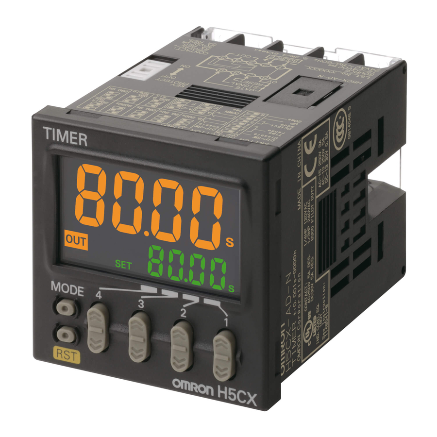
Digital Timer
H5CX-@-N
Ultra-compact Timer Provides Advanced
Functions and Security Settings.
Basic Features
• Short body with depth of only 59 mm (for 24-VAC / 12 to 24-VDC Models with
*1
Screw Terminals).
• Character height of 12 mm for better readability (on models with 4 digits).
• The present value display characters can be switched between red, green,
*2
and orange.
Safety and Reliability
• Power supply circuit and input circuits are isolated for safety and reliability.
• New set value limit and output counter functions have been added.
Other Features
• Front Panel can be changed to white or light gray.
• Models with instantaneous contact output added to the series.
*1. For 100 to 240 VAC Models with Screw Terminals 78 mm, Models with Sockets: 63.7 mm
(case dimension).
*2. The H5CX-A11, H5CX-L8 and H5CX-B Timers have only red characters.
*3. Specifications: 100 to 240 VAC
*4. Replacement Front Panels sold separately.
Features
Basic Features
Ultra Short Body
The body depth has been greatly reduced. Helps in making thinner
control panels. (Models with Screw Terminals)
24-VAC / 12 to 24-VDC Models with Screw Terminals: 59 mm
100 to 240-VAC / VDC Models with Screw Terminals: 78 mm
Models with Sockets: 63.7 mm (case dimension)
* The shortest body for a timer with isolated power supply and input circuits and a maximum
ambient temperature of 55°C (according to OMRON investigation in June 2009).
New models
Easier to Read
For better readability, the character height for the present value display
is 12 mm (on models with 4 digits), the largest class in the industry. The
wide viewing angle and brightness provide excellent visibility.
The number of display segments has also been increased to make
settings easier to understand, and the present value display can be
switched between red, green and orange so that output status can be
seen from a distance.
Model with 4 Digits Model with 6 Digits
10 mm
12 mm
(actual size)
(actual size)
(Display example)
Note: The H5CX-A11 and H5CX-L8 Timers have only red characters.
The Easiest Operation
Operation is simplified by the
Up/Down Keys for each digit
on 4-digit models and Up Keys
for each digit on 6-digit
models.
*4
*
Previous
models
New
Previous
models
models
Easy to read from the top, bottom, and sides!
Model with 4 Digits
Model with 6 Digits
*3
Refer to "Safety Precautions" on page 41.
Safety and Reliability
Isolated Power Supply and Input Circuits
Power supply circuit and input circuits are isolated for safety and
reliability.
Previous non-isolated timers had wiring restrictions and could be damaged if
wired incorrectly. The New H5CX removes these worries.
Output terminal on PLC
Previous
H5CX
Input terminal
AC power
*2
supply
0-V terminal
*2. The AC power supply ground is on the commercial power supply side.
*1. New Models (H5CX-@-N) with 100 to 240-VAC specifications.
Set Value Limit
You can set an upper limit for the set value to prevent unexpected
operation of output devices caused by setting mistakes.
Worry-free operation
is achieved with the
New H5CX by
restricting the time
that can be set.
Output Counter
The output counter counts the number of times the output turns ON
(alarm display, count monitoring, count in increments of 1,000). This
counter is useful in managing the service life of the Timer or the load.
*1
or other device
COM terminal
Forget These
Worries with the
–V
+V
New H5CX
Stabilized DC
power supply
1
Advertisement
Table of Contents

Related Manuals for Omron H5CX-N


Summary of Contents for Omron H5CX-N
- Page 1 Ultra-compact Timer Provides Advanced Functions and Security Settings. Basic Features • Short body with depth of only 59 mm (for 24-VAC / 12 to 24-VDC Models with Screw Terminals). • Character height of 12 mm for better readability (on models with 4 digits).
-
Page 2: Other Features
Worry-free application is possible in locations subject to water. Note: When the Y92S-29 Waterproof Packing is used. Key Protection Black White Light gray Select from any of seven protection patterns. Use the best one for the (standard) application. You can replace the Front Panel. New Modes Models with Instantaneous Contact Output Modes, such as a stopwatch mode (Mode S), have been added. -
Page 3: Model Number Legend
F-1: Cumulative output (DPST) PNP inputs) 0.1 to 99999.9 h Note: 1. The functions that are provided depend on the model. Check detailed specifications before ordering. 2. Refer to page 33 and later for information on H5CX-B Timers (6-digit display). - Page 4 Y92P-CXT4B Black (N1.5) Note: 1. You can change the color of the front panel when mounting the Timer. The Timer is shipped with a black (N1.5) Front Panel. 2. "TIMER" is printed on the front of Replacement Front Panels. Soft Cover...
-
Page 5: Specifications
4 digits Digits 0.001 s to 9.999 s, 0.01 s to 99.99 s, 0.1 s to 999.9 s, 1 s to 9999 s, 1 s ti 99 min 59 s Time ranges 0.1 m to 999.9 min, 1 min to 9999 min, 1 min to 99 h 59 min, 0.1 h to 999.9 h, 1 h to 9999 h... - Page 6 4.5 kV (between current-carrying terminal and exposed non-current- A can be switched if L/R is 7 ms. In both cases, a carrying metal parts) for 100 to 240 VAC 1.5 kV for 24 VAC/12 to 24 VDC life of 100,000 operations can be expected.
-
Page 7: Applicable Standards
*2. The H5CX-L@ does not have a gate input. Response Delay Time When Resetting (Transistor Output) The following table shows the delay from when the reset signal is input until the output is turned OFF. (Reference value) Minimum reset signal width... -
Page 8: Connections Block Diagram
Input circuits circuit Key switch circuit Note: Basic insulation is provided between the power supply circuit and the input circuits. However, basic insulation is not provided in the H5CX-@D-N. Terminal Arrangement Confirm that the power supply meets specifications before use. -
Page 9: Input Circuits
Input Connections The inputs are no-voltage (closed or open) inputs or voltage inputs except for the H5CX-L8@. (The inputs of the H5CX-L8@ are no-voltage inputs only. The H5CX-L8E@ does not have an input.) No-voltage Inputs (NPN Inputs) Open Collector... - Page 10 5. Time Unit Indicators Front View (Color is same as present value display.) 12. Key-protect Switch (If the time range is 0 min, 0 h, 0.0 h, or 0 h 0 min, these indicators flash to indicate (Default setting) (Disabled) (Enabled) timing operation.)
- Page 11 Y92S-29 (order separately) Panel Y92F-30 (order separately) P3G-08 (order Waterproof Packing Flush Mounting Adapter separately) Back-connecting Socket H5CX -L8@-N 92.3 (51) P2CF-08(-E) (order separately) Front Connecting Socket 84.8 * These dimensions vary with the type of DIN track (reference value).
- Page 12 Therefore, it is recommended that resin products are replaced regularly. Front Panel (Replacement Part) You can change the color of the front panel when mounting the Timer. Protecting the Timer in Environments Subject to Oil The Timer is shipped with a black (N1.5) Front Panel.
- Page 13 Note: Round crimp terminals cannot be used on Finger-safe Sockets. Use forked crimp terminals. Back-connecting Sockets Terminal arrangement Model Dimensions and internal connections P3G-08 27 dia (Bottom View) P3GA-11 27 dia 25.6 (Bottom View) 16.3 Note: A Y92A-48G Terminal Cover can be used with the Socket to create a finger-safe construction.
-
Page 14: End Plate
Twelve, 6.4 dia 47.7×47.7 48×48 Y92A-48G 16.5 24.6 27.6 47.4 Note: The Terminal Cover can be used with a Back-mounting Socket (P3G-08 or P3GA-11) to create a finger-safe construction. Optional Products for Track Mounting Mounting Track PFP-100N ±0.15 PFP-50N ±0.3 ±0.15... -
Page 15: Operating Procedures
Mode F: Cumulative (Timer does not reset when power comes ON.) After making DIP switch settings for basic operation, advanced functions can be added using the operation keys on the front panel. Refer to Step2 on page 16 for details. - Page 16 *1. If the mode is switched to the function setting mode during operation, operation will continue. *2. Changes made to settings in function setting mode are enabled for the first time when the mode is changed to run mode. Also, when settings are changed, the timer is reset (time initialized and output turned OFF).
- Page 17 H5CX-A@-N/-L@-N Timer From previous To previous page page Set the digits for the set value limit using the corresponding keys. Set value upper limit 9999 (9999) Set the key protect level using the keys. Key protect level kp-1 kp-2 kp-3...
- Page 18 Output Mode (outm) Orange Set the output mode. The possible settings are A, A-1, A-2, A-3, b, b-1, d, E, F, Z and S. Orange Only output modes A, A-2, E, and F can be set using the DIP switch.
- Page 19 Present Value and ON Duty Ratio (Output Mode = Z) The present value is displayed in the main display and the ON duty ratio is displayed in the sub-display. Set the ON duty ratio used in ON/ OFF-duty-adjustable flicker mode (Z) as a percentage.
- Page 20 Control output one-shot time period. Set value Note: Output is instantaneous when setting is 0. Set value DOWN Mode A-3: Power ON delay 2 (Timer does not reset when power comes ON.) Basic operation Detailed operation Power Power Start signal...
- Page 21 Set the value to at least 100 ms (contact Set value output type). DOWN Mode b-1: Repeat cycle 2 (Timer does not reset when power comes ON.) Basic operation Detailed operation Sustained Output Power...
- Page 22 H5CX-A@-N/-L@-N Timer Mode d: Signal OFF delay (Timer resets when power comes ON.) Basic operation Detailed operation Power Power Start signal Start signal input Timing Gate Output Reset * Start signal input is enabled during timing. The control output is ON when the start signal is ON Control output (except when the power is OFF or the reset is ON).
- Page 23 Instantaneous contacts, NO t = Set time, Rt = Reset time (0.5 s min.), t – a < t (Indicates the time is less than the set time.) Mode b: Repeat cycle 1 (Timer resets when power comes ON.) Basic operation...
- Page 24 Instantaneous contacts, NO t = Set time, dty = ON duty time, Rt = Reset time (0.5 s min.), t – a < t (Indicates the time is less than the set time.) Note: H5CX-L8E@-N Precautions Set the Timer’s set value before using the Timer in a self-holding circuit.
- Page 25 Changes to DIP switch settings are enabled when the power is turned ON. (Perform DIP switch settings while the power is OFF.) After making DIP switch settings for basic operation, advanced functions can be added using the operation keys on the front panel. Refer to Step3...
- Page 26 *1. If the mode is switched to the function setting mode during operation, operation will continue. *2. Changes made to settings in function setting mode are enabled for the first time when the mode is changed to run mode. Also, when settings are changed, the timer is reset (time initialized and output turned OFF).
- Page 27 (KP-1) (KP-2) (KP-3) (KP-4) (KP-5) (KP-6) (KP-7) *1. Set the digits for the output ON alarm set value using the corresponding Output ON keys. count alarm set value/ monitor value • Models without Instantaneous Contact Outputs Output ON 9999...
- Page 28 Present value ON set time Note: 1. The display will automatically show the OFF set time when the OFF time is being timed and the ON set time when the ON time is being timed. Note: 2. H5CX-L8E@-N Precautions Set the Timer’s set value before using the Timer in a self-holding circuit.
- Page 29 DOWN Set the value to at least 100 ms (contact output ON time type). Mode toff-1: Flicker OFF start 2 (Timer does not reset when power comes ON.) Basic operation Detailed operation Power Power...
- Page 30 Instantaneous contacts, NO t-on = ON time, t-off = OFF time, Rt = Reset time (0.1 s min.), t – a < t-off and t – b < t-on (Indicates the time is less than the set time.) Mode ton: Flicker ON start 1 (Timer resets when power comes ON.)
- Page 31 Select whether the H5CX is used as a timer or a twin timer in timer/twin timer selection mode. The H5CX is also equipped with a DIP switch monitor function, a convenient function that enables the settings of the DIP switch pins to be confirmed using the front display.
-
Page 32: Self-Diagnostic Function
H5CX-A@-N/-L@-N Key Protect Level When the key-protect switch is set to ON, it is possible to prevent setting errors by prohibiting the use of certain operation keys by specifying the key protect level (KP-1 to KP-7). The key protect indicator is lit while the key-protect switch is set to ON. -
Page 33: Specifications Ratings
IEC IP66, UL508 Type 4X (indoors) for panel front surface only and only when Y92S-29 Waterproof Packing is used Digits 6 digits Time range 0.01 s to 9999.99 s, 1 s to 99 h 59 min 59 s, 0.1 min to 99999.9 min, 0.1 h to 99999.9 h Timer mode Elapsed time (Up) Input signals Signal, reset, gate : 1 kΩ... - Page 34 Signal start for transistor output model: ±0.005%±3 ms max. (See note 1 and 2.) and setting error If the set value is within the sensor waiting time at startup the control output of the H5CX will not turn ON until the sensor waiting (including temperature and time passes.
- Page 35 Power for load connected to the H5CX. Input Connections The inputs of the H5CX-B are no-voltage (short-circuit or open) inputs or voltage inputs. No-voltage Inputs (NPN Inputs) Open Collector Voltage Output Contact Input DC Two-wire Sensor...
- Page 36 DIP switch pins 6 to 8, thus preventing is ON. setting errors. If the key protect switch is ON, you will not be able to switch to The Key-protect Switch can be turned ON and OFF while the power Function Setting Mode.
-
Page 37: Operation In Run Mode
Enabled Note: 1. All the pins are factory-set to OFF. 1 2 3 4 5 6 7 8 2. DIP switch settings are effective when the power is turned ON again. (Set the DIP switch before installation and power-up.) Operation in Run Mode Set the digits for the set values using the corresponding Key. - Page 38 *1. If the mode is switched to the function setting mode during operation, operation will continue. *2. Changes made to settings in function setting mode are enabled for the first time when the mode is changed to run mode. Also, when settings are changed, the timer is reset (time initialized and output turned OFF).
-
Page 39: Explanation Of Functions
*2. The normal display and will appear alternately. When the Reset Key is pressed, will no longer be displayed even if the alarm set value is exceeded. (Monitoring is possible, however, because the Timer will continue without clearing the output ON count.) -
Page 40: Timing Charts
Use the H5CX with signal start if timer accuracy is required. Note: 1. The forecast value = set value - forecast set value 2. The forecast set value is used to set the deviation for the set value. -
Page 41: Precautions For Safe Use
• Do not connect more than two crimp terminals to the same terminal. Minor injury due to explosion may occasionally occur. • Up to two wires of the same size and type can be inserted into a Do not use the Timer where subject to flammable or single terminals. -
Page 42: Precautions For Correct Use
Always check the wiring sufficiently before use. • H5CX-A@-N/-L@-N: • An inrush current of approx. 10 A will flow for a short time when the Basic insulation is provided between the power supply and input power supply is turned ON. If the capacity of the power supply is terminals. -
Page 43: Warranty And Application Considerations
CONTRACT, WARRANTY, NEGLIGENCE, OR STRICT LIABILITY. In no event shall the responsibility of OMRON for any act exceed the individual price of the product on which liability is asserted. IN NO EVENT SHALL OMRON BE RESPONSIBLE FOR WARRANTY, REPAIR, OR OTHER CLAIMS REGARDING THE... - Page 44 Industrial Component Division 2-2-1 Nishikusatsu, Kusatsu-shi, Shiga, 525-0035 Japan OMRON ASIA PACIFIC PTE. LTD. Tel: (81) 77-565-5160/Fax: (81) 77-565-5569 No. 438A Alexandra Road # 05-05/08 (Lobby 2), Alexandra Technopark, Singapore 119967 Tel: (65) 6835-3011/Fax: (65) 6835-2711 Regional Headquarters OMRON (CHINA) CO., LTD.