Advertisement
Quick Links
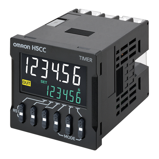
H5CC-AWSD
Digital Timer
INSTRUCTION MANUAL
EN
Thank you for purchasing the OMRON Product.
To ensure the safe application of the Product, read this
manual carefully before using the Product and always
keep it close at hand when the Product is in use.
OMRON Corporation
©All Rights Reserved
3616495-0A (Side-A)
For details, refer to the latest datasheet (L220-E1).
SUITABILITY FOR USE
Omron Companies shall not be responsible for conformity with any
standards, codes or regulations which apply to the combination of the
Product in the Buyer's application or use of the Product. At Buyer's request,
Omron will provide applicable third party certification documents identifying
ratings and limitations of use which apply to the Product. This information
by itself is not sufficient for a complete determination of the suitability of the
Product in combination with the end product, machine, system, or other
application or use. Buyer shall be solely responsible for determining
appropriateness of the particular Product with respect to Buyer's
application, product or system. Buyer shall take application responsibility in
all cases.
NEVER USE THE PRODUCT FOR AN APPLICATION INVOLVING
SERIOUS RISK TO LIFE OR PROPERTY OR IN LARGE QUANTITIES
WITHOUT ENSURING THAT THE SYSTEM AS A WHOLE HAS BEEN
DESIGNED TO ADDRESS THE RISKS, AND THAT THE OMRON
PRODUCT(S) IS PROPERLY RATED AND INSTALLED FOR THE
INTENDED USE WITHIN THE OVERALL EQUIPMENT OR SYSTEM.
Mounting and Panel-cutout Dimensions Diagram
Mounting Dimensions (Unit: mm)
H5CC-AWSD
Front panel dimensions
are the same for all
Y92S-P6 (provided)
models.
Waterproof Packing
Y92F-30 (provided)
Flush Mounting Adapter
Panel
H5CC
TIMER
48
(48)
48
7.5
57.5
Package Contents
• Digital Timer
• Instruction manual (this
document)
• Mounting Adapter, Waterproof
Packing, Terminal Cover
Nomenclature
Operation Key
8. UP Keys (UP1 to UP6)
H5CC
TIMER
9. DOWN Keys (DW1 to DW6)
4
10. Reset operation (UP6+DW6)
.
Press RST keys (UP6+DW6) simultaneously for at least one second.
1
1
5
.
LED on each key starts blinking. If not blink, that because the keys are not pressed
2
2
6
simultaneously. In this case, release the keys after pressing for at least 1 second,
3
and restart from 1. Do not release the keys until the LED starts blinking. Otherwise
7
8
the setting value may change.
.
10
12
3
Press and hold until the LED turns off. If you release the keys while blinking, the
9
reset operation will be interrupted.
11
11. Mode operation (UP1+UP3 or DW1+DW3)
<Change of setting item>
.
Press MODE keys (UP1+UP3 or DW1+DW3) simultaneously to switch setting items.
1
<Move to Function Setting Mode>
.
Press MODE key (UP1+UP3 or DW1+DW3) for at least 2 seconds simultaneously.
Display Section
1
.
LEDs on UP1 (DW1) and UP3 (DW3) key start blinking. If not blink, that because the
2
1. Key Protect Indicator
(yellow)
keys are not pressed simultaneously. In this case, release the keys after pressing
2. Control Output Indicator
(yellow)
for at least one second, and restart from 1. Do not release the keys until the LEDs
start blinking.
Otherwise the setting value may change.
3. Reset Indicator
(yellow) (Lit when the
.
reset input or Reset operation is ON.)
3
Press and hold until the LED turns off. If you release the keys during blinking, the
mode will not be moved to Function Setting Mode.
4. Present Value Display (Main Display)
12. Status indicator
Character height: 10 mm (white)
<When Run mode is selected.>
5. Time Unit Indicators
(green) (If the
• When the indicator display mode is on, the LED indicator shows the percentage of
time range is 0 min, 0.0 min, 0 h, 0.0 h, or
the present value from 0 to 100%.
0 h 0 min, these indicators flash to
• When the indicator display mode is all off or all lit, the LEDs are all off or all lit.
indicate timing operation.)
Note: When you press the UP key or the DOWN key, the indicator display or all-lit
6. Set Value Display (Sub-display)
display goes off, and the LED indicator of the pressed key lights up or blinks.
Character height: 6 mm (green)
<When Function Setting Mode is selected>
7. Set Value 1, 2 Indicator
(green)
• The LED indicators at the settable key positions will light.
Operation in Function Setting Mode
Note: Refer to the datasheet for detailed parameter settings.
Change from RUN Mode to Function Setting Mode.
Set the parameters using the UP Key or DOWN Key.
The characters displayed in reverse video are the default settings.
Press UP1+UP3 keys once to move to the previous parameter.
Press DW1+DW3 keys once to move to the next parameter.
Display
Parameter name
Set value
Time range
*1
timr
Output mode
,
outm
a
f-1
Input signal width
,
iflt
20ms
1ms
NPN/PNP input mode
,
imod
npn
pnp
Absolute value setting/ forecast
,
setn
ofst
abs
value setting
1 ~
Set value upper limit
sl-h
999999
1 ~
Forecast setting upper limits
pl-h
999999
,
,
,
kp-1
kp-2
kp-3
kp-4
Key protect level
kypt
,
,
kp-5
kp-6
kp-7
Output 1 inversion
,
ot1i
n-o
n-c
Output 2 inversion
ot2i
,
n-o
n-c
Indicator display mode
,
,
indc
on
alof
allt
Output 1 (OUT1) ON count alarm
0 ~
~ 9999
on1a
100
set value
Output 2 (OUT2) ON count alarm
0 ~
~ 9999
on2a
set value
100
Output 1 (OUT1) ON count
---
on1c
monitor value
Output 2 (OUT2) ON count
---
on2c
monitor value
0.0 ~
~ 99.9
Total run time alarm set value
ot-a
10.0
Total run time monitor value
---
ot-c
Software version
---
ver
*1 The set values for the time range are as follows:
Display
Set value
~
----.--
0.01s
9999.99s (default setting)
s
~
0.1s
99999.9s
-----.-
s
~
------
1s
999999s
s
~
0h0min01s
99h59min59s
--:--:--
hms
~
-----.-
0.1min
99999.9min
m
~
1min
999999min
------
m
~
----:--
0h01min
9999h59min
hm
~
0.1h
99999.9h
-----.-
h
~
------
1h
999999h
h
~
0.001s
999.999s
---.---
s
Self-diagnostic Functions
The following displays will appear if an error occurs.
Main
Sub-
Output
Description
Correctionmethod
display
display
status
Either perform Reset
operation or reset
Not lit CPU error
OFF
e1
the power supply.
Turn ON the power
Not lit Memory error (RAM)
OFF
e2
again.
Memory error
OFF
Reset operation
e2
sum
(non-volatile memory) *1
Total run time or Output
No
No
Rplc
Reset operation *2
ON count has reached
*3
change
change
the maintenance forecast.
SAFETY PRECAUTIONS
Keys to Warning Symbols
Indicates a potentially hazardous situation which, if not
CAUTION
avoided, is likely to result in minor or moderate injury or in
property damage.
CAUTION
Do not allow pieces of metal, wire clippings, or fine metallic shavings or
fillings from installation to enter the product. Doing so may occasionally
result in electric shock, fire, or malfunction.
Do not use the Timer where subject to flammable or explosive gas. Minor
injury due to explosion may occasionally occur.
Fire may occasionally occur. Tighten the terminal screws to the rated torque.
H5CC terminals and P3GA-11/P3G-08 Socket terminals: 6.55 to 7.97 lb-in
(0.74 to 0.90 N·m)
P2CF Socket terminals: 4.4 lb-in (0.5 N·m)
Do not touch any of the terminals while power is being supplied. Be sure to
mount the terminal cover after wiring. Minor injury due to electric shock
may occasionally occur.
Do not disassemble, modify, or repair the Timer or touch internal
components. Minor electric shock, fire, or malfunction may occasionally
occur.
Precautions for Safe Use
) When mounting the Timer to a panel, tighten the two mounting screws alternately, a little
1
at a time, so as to keep them at an equal tightness. If the panel screws are tightened
unequally, water may enter the panel.
) Store the Timer at the specified temperature. If the Timer has been stored at a
2
°
temperature of less than -10
C, allow the Timer to stand at room temperature for at least
3 hours before use.
) Mounting the Timer side-by-side may reduce the life expectancies of internal components.
3
) Use the Timer within the specified ranges for the ambient operating temperature and humidity.
4
) Do not use or store the product in the following locations:
5
• Locations subject to sudden or extreme changes in temperature.
• Locations where high humidity may result in condensation.
• Locations with excessive vibration or shock.
• Locations subject to water.
Power supply voltage
Panel-cutout Dimensions
Allowable voltage fluctuation range 85% to 110% of rated supply voltage (12 to 48 VDC: 90% to 110%)
Power consumption
Diagram (Unit: mm)
Operating temperature range
Standard panel cutout is shown in the following
Storage temperature range
diagram. (conforms to DIN 43700)
Operating humidity range
A space of 15 mm or greater (a panel cut-out
Altitude
distance of 60 mm or greater) is recommended
Recommended fuse
towards the Adapter's hook side to enable easier
Weight
mounting work.
Installation environment
Input method
48
Control output
1. The thickness of a mounting panel should be
Degree of protection
1 to 5 mm.
* Individual mounting: Degree of protection on the front panel of the Timer conforms when all
2. It is possible to mount Timers side-by-side.
(But only towards the non-hook side.)
n Units mounted
side-by-side
A
1
A (48n 2.5)
0
3. If the products are mounted side by side,
water resistance will be lost.
(UP 1, 2, 3, 4, 5 and 6 from right to left)
(DW 1, 2, 3, 4, 5 and 6 from right to left)
UP1+UP3 or DW1+DW3
(2 s min.)
Power
Run
Function
ON
mode
setting mode
UP1+UP3 or DW1+DW3
(2 s min.)
Comments
---
---
---
---
---
---
Displayed only when forecast value setting is made.
,
---
---
---
---
×
1,000
×
1,000
The monitor value is only displayed. It cannot be set.
×
1,000
The monitor value is only displayed. It cannot be set.
• Confirm that the power supply to the Timer
×
1,000
Unit: yea
The Total run time monitor value is only displayed.
It cannot be set.
The software version is only displayed. It cannot be set.
*1. This includes times when the life of the non-volatile
memory has expired.
Set value
*2. This is displayed if the alarm set value for either of the
after reset
two outputs is exceeded if a model with two outputs
is used. The total ON count will not be cleared by
using Reset operation.
No change
*3. The normal display and
will appear alternately.
Rplc
When Reset operation is performed,
will no
Rplc
longer be displayed even if the alarm set value is
exceeded. (Monitoring is possible, however, because
No change
the Timer will continue without clearing the total run
time and the output ON count.) If the power supply is
Factory
turned OFF/ON after the
display is turned OFF
Rplc
setting
by Reset operation,
will be displayed again. In
Rplc
order to prevent the display even after the power
supply is turned OFF/ON, change the alarm set value
No change
to equal to or greater than the count value, or change
the alarm set value to 0 to be invalid.
• Locations subject to oil.
• Locations prone to icing.
• Locations subject to exposure chemicals.
• Locations subject to bugs and small animals.
) Do not use this Timer in dusty environments, in locations where corrosive gasses are
6
present, or in locations subject to direct sunlight.
) Install the Timer well away from any sources of static electricity, such as pipes
7
transporting molding materials, powders, or liquids.
) Internal elements may be destroyed if a voltage outside the rated voltage range is applied.
8
) Be sure that polarity is correct when wiring the terminals.
9
) Separate the Timer from sources of noise, such as devices with input signals from power
10
lines carrying noise, and wiring for I/O signals.
) Do not connect more than two crimp terminals to the same terminal.
11
) Up to two wires of the same size and type can be inserted into a single terminals.
12
) Use the specified wires for wiring.
13
Applicable Wires: AWG 18 to AWG 22, solid or twisted, copper
Wiring stripping length: 5 to 6 mm (recommended)
) Install a switch or circuit breaker that allows the operator to immediately turn OFF the
14
power, and label it to clearly indicate its function.
When the Timer is operated with no-voltage input (NPN input), approximately 14 V is
15)
output from the input terminals. Use a sensor that contains a diode.
) Use a switch, relay, or other contact so that the rated power supply voltage will be reached
16
within 0.1 second. If the power supply voltage is not reached quickly enough, the Timer may
malfunction or outputs may be unstable. Use a switch, relay, or other contact so that the
rated power supply voltage will be reached within 0.1 second. If the power supply voltage is
not reached quickly enough, the Timer may malfunction or outputs may be unstable.
) Use a switch, relay, or other contact to turn the power supply OFF instantaneously.
17
Outputs may malfunction and memory errors may occur if the power supply voltage is
decreased gradually.
18) If the set value is changed as follows during a timing operation, the output will turn ON because
of the use of a constant read-in system:
(1) For forecast value setting
Changing the value so that Present value ≥ Set value turns ON output 2 (control output).
Changing the value so that Present value ≥ Forecast value (The forecast value = set value -
forecast set value) turns ON output 1 (forecast output).
(2) For absolute value setting
Changing the value so that Present value ≥ Set value 2 turns ON output 2 (control output 2).
Changing the value so that Present value ≥ Set value 1 turns ON output 1 (control output 1).
When the set value is 0, the output turns ON the moment the signal is input. The reset
operation turns OFF the output.
) Do not use organic solvents (such as paint thinners or benzine), strong alkali, or strong acids.
19
) Confirm that indications are working normally, including the backlight LEDs, and LCD. The
20
indicator LEDs, LCD, and resin parts may deteriorate more quickly depending on the
application environment, preventing normal indications. Periodic inspection and
replacement are required.
) The waterproof packing may deteriorate, shrink, or harden depending on the application
21
environment. Periodic inspection and replacement are required.
Ratings (Specifications)
12 to 48 VDC/24 VAC, 50/60 Hz
Approx. 5.4 VA/3.2 W at 24 VAC/12 to 48 VDC
°
°
-10 to 55
C (-10 to 50
C if Timers are mounted side by side)
(with no icing or condensation)
°
-25 to 70
C (with no icing or condensation)
25% to 85%
2,000 m max.
0216.100
Approx. 115 g (main unit only)
Ⅲ
Over-voltage category
, pollution degree 2, indoor use only
(IEC 61812-1)
Ω
No-voltage input
ON impedance: 1 k
max. (Leakage current: 12 mA when 0
ON residual voltage: 3 V max., OFF impedance: 100 k
Voltage input
High (logic) level: 4.5 to 30 VDC, Low (logic) level: 0 to 2 VDC
Ω
(Input resistance: approx. 4.7 k
)
No-voltage (NPN) input/voltage (PNP) input (switchable)
Solid state output
Open collector 30 VDC max., 100 mA max.
Residual voltage 1.5 VDC max. (Effective value: Approx. 1 VDC)
Leakage current 0.1 mA max.
IEC IP66
of the following conditions are satisfied:
• The Y92S-P6 waterproof packing and Y92F-30 mounting adapter are used with the Timer.
Use only these parts for replacement.
Operating Procedures
Forecast Value Setting
Operation in Run Mode
0.0
Present value
Set value
0.0
* UP1+UP3 or
DW1+DW3
0.0
Present value
0.0
Forecast set value
Basic Operation
Set value
Forecast set value
Forecast value
0
Forecast output (OUT1)
Control output (OUT2)
• The control output (output 2) turns ON when the present value reaches the set value.
• Forecast output (OUT1) turns ON when the present value reaches the forecast value.
The forecast value is the set value minus the forecast set value.
• If the forecast set value ≥ set value, OUT1 (forecast output) will turn ON as soon as timing starts.
• If the set value equals 0, the forecast output (output 1) and control output (output 2) will turn ON as soon as
timing starts.
Absolute Value Setting
Operation in Run Mode
0.0
Present value
Set value 1
0.0
* UP1+UP3 or
DW1+DW3
0.0
Present value
0.0
Set value 2
Basic Operation
Set value 2
Set value 1
0
Control output 1 (OUT1)
Control output 2 (OUT2)
• OUT1 (control output 1) turns ON when the present value reaches set value 1.
• OUT2 (control output 2) turns ON when the present value reaches set value 2.
• If the set value equals 0, the control output will turn ON as soon as timing starts.
Terminal Arrangement
meets specifications before use.
0 V
6
7
8
* Terminals 7 and 10 have the same reset
12
function. The same function will be
performed whichever terminal is connected.
Terminals 7 and 10 are not connected
1
2
3
internally, so do not use them for cross
OUT2
wiring.
(-)
(+)
Output Mode
Mode A: Signal ON delay (Timer resets when power
comes ON.)
• Timing starts when the start signal goes ON.
• While the start signal is ON, the timer starts when the
power comes ON or when the reset input goes OFF.
• A sustained control output is used.
Output Operation
Output Operation
Power
Chart
*
Signal
Timing
Forecast output
Control output
Forecast output
OUT1
OUT1
Control output
Control output
Control output
OUT2
OUT2
*Start signal input is disabled during timing.
The names in parentheses are used for the absolute value setting.
1) Read this manual carefully before using the product.
2) An inrush current of approx. 14 A will flow for a short time when the power supply
3) Make sure the power supply voltage and loads are within the specifications and
4) Take caution that signal reception is possible, impossible, or indefinite during the
5) No input signals will be accepted from 5 to 505 ms for H5CC-A
6) Inrush current generated by turning ON or OFF the power supply may deteriorate
7) Make sure that all settings are appropriate for the application. Unexpected
8) Do not leave the Timer for long periods at a high temperature with output current
9) Non-volatile memory is used as backup memory when the power is interrupted.
10) Dispose of the product according to local ordinances as they apply.
11) Do not use because it may be damaged inside the product when the product fall
12) Confirm the wiring the input and output terminals correctly before power is supplied.
13) Do not use the product near radio wave receivers. Doing so may cause incoming
14) Install product so that the load doesn't span the product body.
15) H5CC models with a 24 to 240 VAC/DC power supply use a transformer-free
16) Do not wire the terminals that are not used.
17) If there is a transformer or other device with a large inductance component on the
18) Do not use in a circuit with the waveform is distorted. The error will increase due
Conformance to
EN/IEC Standards
• When conforming to EMC standards,
refer to the information provided in this
Instruction Manual for cable selection
Inputs
and other conditions.
• This is a class A product. In residential
areas it may cause radio interference, in
which case the user may be required to
take adequate measures to reduce
interference.
• Basic insulation is provided between
Ω
power supply and input terminals, between
),
Ω
power supply and output terminals, and
min.
between input and output terminals.
Outputs
• Basic insulation is provided between
power supply and output terminals, and
between input and output terminals.
When double insulation or reinforced
insulation is required, apply double
insulation or reinforced insulation as
defined in IEC 60664 that is suitable for
the maximum operating voltage with
clearances or solid insulation.
• Connect the input and output terminals to
devices that do not have any exposed
charged parts.
Notice to Users of the H5CC in the USA and Canada
Please use the following installation information instead of the general information in
the instruction manuals in order to use the product under certified conditions of UL and
CSA when the product is installed in the USA or Canada. These conditions are required
by NFPA 70, National Electrical Code in the USA and the Canadian Electrical Code, Part
I in Canada and may vary from information given in the product manuals or safety
precautions.
• Installation in a Panel
H5CC is normally installed on a flat surface in an operation panel. Use a Type 1
Enclosure for the operation panel.
• Environment
Surrounding Air Temperature: -10 to 40
• Accessories (Order Separately)
* Each time the UP1+UP3 or
DW1+DW3 Keys are pressed,
the set value display (6) will
switch between the set value
and the forecast set value.
The inputs of the Timer are no-voltage (short-circuit or open) inputs or
voltage inputs.
Present value
* Each time the UP1+UP3 or
DW1+DW3 Keys are pressed,
the set value display (6) will
switch between set values 1
and 2.
Present value
* • The solid state output is insulated from the
internal circuitry by a photocoupler, so the
solid state output can be used as both NPN
and PNP output.
NPN Output
PNP Output
9
10
Load
Load
+
+
Power for load
Power for load
13
OUT1
• The diode connected to
Timer
*
the collector of the
output transistor is used
to absorb inverted
Inductive
4
5
voltage that is
load
+
generated when an
inductive load is
Power for load
connected to the H5CC.
OMRON Corporation
Mode F-1: Cumulative (Timer does not reset
when power comes ON.)
Regional Headquarters
• Start signal enables timing (timing is stopped
OMRON EUROPE B.V.
when the start signal is OFF or when the power
Wegalaan 67-69,2132 JD Hoofddorp
is OFF).
The Netherlands
• A sustained control output is used.
Tel: (31)2356-81-300
Fax: (31)2356-81-388
Power
Chart
OMRON ASIA PACIFIC PTE. LTD.
Signal
No. 438A Alexandra Road #05-05/08
Timing
Timing
(Lobby 2), Alexandra Technopark,
Control output
Sustained
OUT1
OUT1
Singapore 119967
Control output
Tel: (65) 6835-3011
OUT2
OUT2
Fax: (65) 6835-2711
The names in parentheses are used for
the absolute value setting.
Note: Specifications subject to change without notice.
Precautions for Correct Use
is turned ON. If the capacity of the power supply is not sufficient, the Timer may
not start. Be sure to use a power supply with sufficient capacity.
ratings for the product.
following periods after power ON/OFF. To allow for the startup time of peripheral
devices (sensors, etc.), the Timer starts timing operation between 200 to 250 ms
after power is turned ON. For this reason, if the set value is 249 ms or less in
operations where timing starts from power ON, the time until output turns ON will
be a fixed value between 200 and 250. The present value display will start from
250 ms. (Normal operation is possible for set values of 250 ms or more.) In
applications where a set value of 249 ms or less is required, use start timing with
signal input.
/L8
, from 5 to
105 ms for H5CC-A11F, and from 5 to 1005 ms for H5CC-AU
after the power is
turned OFF.
contacts on the power supply circuit. Turn ON or OFF to a device with the rated
current of more than 14 A.
operation resulting in property damage or accidents may occur if the settings are
not appropriate.
in the ON state. Doing so may result in the premature deterioration of internal
components (e.g., electrolytic capacitors). Do not install the product close
contact with the heating element.
The write life of the non-volatile memory is 100,000 writes. The non-volatile
memory is written when the power is turned OFF or when switching from function
setting mode or configuration selection mode to run mode.
by mistake.
radio wave interference.
power supply method in which the power supply terminals are not isolated from
the signal input terminals. In such cases, unwanted current paths may
occasionally burn or destroy internal components depending on the wiring.
Always check the wiring sufficiently before use.
power supply line, the inductance will cause a reverse voltage. If that occurs,
insert a CR filter in the power supply line to reduce the reverse voltage.
to the influence of the distorted waveform.
I/O Functions
Start signal
• Starts timing.
• Resets present value. (The present value
returns to 0.)
• Timing stops and control output turns
Reset
OFF while reset input is ON.
• Reset indicator is lit while reset input is ON.
Gate
• Inhibits timer operation.
Control
Turns ON when the present value reaches
output
the set value.
Forecast
(OUT2)
value
Forecast
setting
Turns ON when the present value reaches
output
the forecast value.
(OUT1)
Control
Turns ON when the present value reaches
output 2
set value 2.
Absolute
(OUT2)
value
Control
setting
Turns ON when the present value reaches
output 1
set value 1.
(OUT1)
Precautions for Compliance with
UL Standards and CSA Standards
Track Mounting/
11-pin
°
Front Connecting
11-pin, finger-safe type
C
Socket
8-pin
8-pin, finger-safe type
Input Connections
No-voltage Inputs (NPN Inputs)
Voltage Output
Open Collector
PLC,
Sensor
Sensor
6
7
8
9
10
6
7
8
9
10
Note: Operate with transistor ON
Note: Operate with transistor ON
Contact Input
Two-wire Sensor
6
7
8
9
10
6
7
8
9
10
Note: Operate with relay ON
Note: Operate with transistor ON
No-voltage Input Signal Levels
Short-circuit level (Transistor ON)
• Residual voltage: 3 V max.
Ω
• Impedance when ON: 1 k
max.
No-contact
(The leakage current is approx. 12 mA when the
Ω
input
impedance is 0
.)
Open level (Transistor OFF)
Ω
• Impedance when OFF: 100 k
min.
Contact input
Use contacts which can adequately switch 10 V, 5 mA
Note 1: The DC voltage must be 30 VDC max.
Applicable Two-wire Sensor
Leakage current: 1.5 mA max.
Switching capacity: 5 mA min.
Residual voltage: 3.0 V DC max.
Operating voltage: 10 V DC
Voltage Inputs (PNP Inputs)
No-contact Input (NPN Transistor)
No-contact Input (PNP Transistor)
Sensor
Sensor
6
7
8
9
10
6
7
8
9
10
Note: Operate with transistor OFF
Note: Operate with transistor ON
Contact input
6
7
8
9
10
Note: Operate with relay ON
Voltage Input Signal Levels
High level (Input ON): 4.5 to 30 V DC
Low level (Input OFF): 0 to 2 V DC
Note 1: The DC voltage must be 30 V DC max.
Ω
Note 2: Input resistance: Approx. 4.7 k
Industrial Automation Company
Kyoto, JAPAN
Contact: www.ia.omron.com
OMRON ELECTRONICS LLC
2895 Greenspoint Parkway, Suite 200
Hoffman Estates, IL 60169 U.S.A.
Tel: (1) 847-843-7900
Fax: (1) 847-843-7787
OMRON (CHINA) CO., LTD.
Room 2211, Bank of China Tower,
200 Yin Cheng Zhong Road,
Pu Dong New Area, Shanghai,
200120, China
Tel: (86) 21-5037-2222
Fax: (86) 21-5037-2200
P2CF-11
P2CF-11-E
P2CF-08
P2CF-08-E
Advertisement

Related Manuals for Omron H5CC-AWSD


Summary of Contents for Omron H5CC-AWSD
- Page 1 OFF or when switching from function occur. Omron Companies shall not be responsible for conformity with any 18) If the set value is changed as follows during a timing operation, the output will turn ON because setting mode or configuration selection mode to run mode.
- Page 2 ) 取り扱いは本書をよ く理解してからおこなって ください。 形 ●警告表示の意味 ださい。 バランスがとれていない場合、 パネルの内部に水が浸入する可能性があります。 ) 電源投入時に短時間ですが突入電流が流れ (約 ) 、 電源の容量によ っては起動 H5CC-AWSD 2) 保管は、 記載された定格範囲内として ください。 また、 -10℃以下で保存後、 使用する場合 しないことがありますので、 充分な容量の電源を使用して ください。 は、 常温に 3 時間以上放置してから通電して ください。 ) 電源電圧および負荷は、 仕様、 定格の範囲内で使用して ください。 注意 正しい取扱いをしなければ、 この危険のために、 時に軽傷・中程...