Table of Contents
Advertisement
http://waterheatertimer.org/How-to-wire-off-delay-timer.html
https://waterheatertimer.org/How-to-wire-twin-timer.html
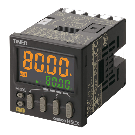
Multifunction Digital Timer
Highly visible display with backlit negative trans-
missive LCD.
Programmable PV color to visually alert when out-
put status changes (screw terminal block models).
Intuitive setting enabled using DIP switch (H5CX-
A/-A11 models) and ergonomic up/down digit
keys.
Twin timer in one body to meet a broader range of
cyclic control application requirements as well as
ON/OFF duty adjustable flicker mode.
PNP/NPN switchable DC-voltage input (H5CX-A/-
A11 models).
Finger-safe terminals (screw terminal block mod-
els).
Meet a variety of mounting requirements:
Screw terminal block models, and pin-style termi-
nal models.
NEMA4/IP66 compliance.
Six-language instruction manual.
Ordering Information . . . . . . . . . . . . . . . . . . . . . . . . . . . . . . . . . 5
Specifications . . . . . . . . . . . . . . . . . . . . . . . . . . . . . . . . . . . . . . 6
Nomenclature . . . . . . . . . . . . . . . . . . . . . . . . . . . . . . . . . . . . . . 8
Operation. . . . . . . . . . . . . . . . . . . . . . . . . . . . . . . . . . . . . . . . . . 9
Setting Procedure Guide . . . . . . . . . . . . . . . . . . . . . . . . . . . . . . 10
Operation (Timer Function) . . . . . . . . . . . . . . . . . . . . . . . . . . . . 11
Operation (Twin Timer Function) . . . . . . . . . . . . . . . . . . . . . . . . 15
Operation in Timer/Twin Timer Selection Mode . . . . . . . . . . . . 19
Timing Charts . . . . . . . . . . . . . . . . . . . . . . . . . . . . . . . . . . . . . . 20
Dimensions . . . . . . . . . . . . . . . . . . . . . . . . . . . . . . . . . . . . . . . . 24
Installation . . . . . . . . . . . . . . . . . . . . . . . . . . . . . . . . . . . . . . . . . 27
Accessories (Order Separately) . . . . . . . . . . . . . . . . . . . . . . . . 29
Precautions . . . . . . . . . . . . . . . . . . . . . . . . . . . . . . . . . . . . . . . . 32
Appendix . . . . . . . . . . . . . . . . . . . . . . . . . . . . . . . . . . . . . . . . . . 35
4
Contents
H5CX
Advertisement
Table of Contents

Related Manuals for Omron H5CX


Summary of Contents for Omron H5CX
-
Page 1: Table Of Contents
LCD. Programmable PV color to visually alert when out- put status changes (screw terminal block models). Intuitive setting enabled using DIP switch (H5CX- A/-A11 models) and ergonomic up/down digit keys. Twin timer in one body to meet a broader range of cyclic control application requirements as well as ON/OFF duty adjustable flicker mode. -
Page 2: Ordering Information
12 to 24 VDC/24 VAC H5CX-ASD H5CX-A11SD H5CX-L8SD Note: The power supply and input circuits for the H5CX-A11/A11S have basic insulation. Other models are not insulated. Model Number Legend: H5CX-@@@@@ 1 2 3 4 5 1. Type classifier 3. Output type... -
Page 3: Specifications
H5CX H5CX Specifications Ratings Item H5CX-A@ H5CX-A11@ H5CX-L8@ Classification Digital timer Rated supply voltage 100 to 240 VAC (50/60 Hz), 24 VAC (50/60 Hz)/12 to 24 VDC (permissible ripple: 20% (p-p) max.) Operating voltage range 85% to 110% rated supply voltage (12 to 24 VDC: 90% to 110%) Power consumption Approx. - Page 4 3 ms max. (See note 2.) voltage influences) (See note 1.) If the set value is within the sensor waiting time at startup the control output of the H5CX will not turn ON until the sensor waiting time passes. Insulation resistance 100 M min.
-
Page 5: Nomenclature
C Control Output Indicator (orange) (Resets present value and output) D Present Value J Up Keys 1 to 4 (red or green (programmable) for H5CX-A models, red for H5CX-A11 K Down Keys 1 to 4 /-L models) Character height: 11.5 mm Front color: Black... -
Page 6: Operation
(See note.) Power supply circuit Note: Power circuit is not insulated from the input circuit, except for H5CX-A11/-A11S, which have basic insulation. I/O Functions Inputs Start signal Stops timing in A-2 and A-3 (power ON delay) modes. Starts timing in other modes. -
Page 7: Setting Procedure Guide
For details on the setting methods, refer to page 12. For details on the setting methods, refer to page 12. Note: At the time of delivery, the H5CX is set for timer operation. Settings for Twin Timer Operation Use the following settings for all models except the H5CX-L8@. -
Page 8: Operation (Timer Function)
2. Changes to DIP switch settings are enabled when the power is turned ON. (Perform DIP switch settings while the power is OFF.) 3. There is no DIP switch on the H5CX-L8@. For details on the setting methods, refer to page 12. - Page 9 0 min 01 s to 99 min 59 s input mode (NPN input) (PNP input) 0.1 min to 999.9 min Only displayed for H5CX-A@ and H5CX-A11@ models. 1 min to 9,999 min Set the display color using the keys. Display color...
- Page 10 H5CX (Timer Function) H5CX (Timer Function) Explanation of Functions Time Range (timr) (Setting possible using DIP switch.) Input Signal Width (iflt) (Setting possible using DIP switch.) Set the range to be timed in the range 0.000 s to 9,999 h. Settings...
- Page 11 H5CX (Timer Function) H5CX (Timer Function) Operation in Run Mode When Output Mode Is Not Z Set each digit for the set value using the corresponding keys. Present value Set value When Output Mode Z Is Selected Set each digit for the ON duty ratio using the corresponding keys.
-
Page 12: Operation (Twin Timer Function)
Operation (Twin Timer Function) Switching from Timer to Twin Timer The H5CX is factory-set for timer operation. To switch to twin timer operation, use the procedure given below. For details, refer to page 35. Power ON Timer/twin timer selection mode... - Page 13 0 min 01 s to 99 min 59 s (NPN input) (PNP input) 0.1 min to 999.9 min Only displayed for H5CX-A@ and H5CX-A11@ models. 1 min to 9,999 min Set the display color using the keys. Display color...
- Page 14 H5CX (Twin Timer Function) H5CX (Twin Timer Function) Explanation of Functions OFF Time Range (oftr) (Setting possible using DIP switch.) Input Signal Width (iflt) (Setting possible using DIP switch.) Set the time range for the OFF time in the range 0.000 s to 9,999 Set the minimum signal input width (20 ms or 1 ms) for signal, h.
- Page 15 H5CX (Twin Timer Function) H5CX (Twin Timer Function) Operation in Run Mode Set the digits for the OFF set time using the corresponding keys. Present value OFF set time Set the digits for the ON set time using the corresponding keys.
-
Page 16: Operation In Timer/Twin Timer Selection Mode
Operation in Timer/Twin Timer Selection Mode Select whether the H5CX is used as a timer or a twin timer in timer/twin timer selection mode. The H5CX is also equipped with a DIP switch monitor function, a convenient function that enables the settings of the DIP switch pins to be confirmed using the front display. -
Page 17: Timing Charts
H5CX H5CX Timing Charts Timer Operation The gate input is not included in the H5CX-L8@ models. One-shot output Either one-shot output or sustained output can be selected. Sustained output Output mode A: Signal ON delay 1 (Timer resets when power comes ON.) Timing starts when the start signal goes ON. - Page 18 H5CX H5CX Output mode b: Repeat cycle 1 (Timer resets when power comes ON.) Timing starts when the start signal goes ON. Sustained The status of the control output is reversed when time Output Power is up (OFF at start).
- Page 19 H5CX H5CX Output mode d: Signal OFF delay (Timer resets when power comes ON.) The control output is ON when the start signal is Power ON (except when the power is OFF or the reset is ON). The timer is reset when the time is up.
- Page 20 H5CX H5CX Twin Timer Operation The gate input is not included in the H5CX-L8@ models. Output mode toff: Flicker OFF start Sustained Timing starts when the start signal goes ON. The status of the control output is reversed when time Output is up (OFF at start).
-
Page 21: Dimensions
H5CX H5CX Dimensions Note: All units are in millimeters unless otherwise indicated. Timer (without Flush Mounting Adapter) H5CX-A/-AS (Flush Mounting) 48x48 44.8x44.8 Note: M3.5 terminal screw (effective length: 6 mm) H5CX-AD/-ASD (Flush Mounting) 48x48 44.8x44.8 Note: M3.5 terminal screw (effective length: 6 mm) - Page 22 H5CX H5CX Dimensions with Flush Mounting Adapter H5CX-A/-AS (Provided with Adapter and Waterproof Packing) Panel Y92S-29 (provided) Waterproof Packing Y92F-30 (provided) Flush Mounting Adapter (51) 98.5 H5CX-AD/-ASD (Provided with Adapter and Waterproof Packing) Panel Y92S-29 (provided) Waterproof Packing Y92F-30 (provided)
- Page 23 H5CX H5CX Dimensions with Front Connecting Socket H5CX H5CX -A11/ -A11D/ H5CX -A11S -A11SD -L8@ 109.7 100.9 103.2 92.3 P2CF-08 P2CF-11 P2CF-11 Note: These dimensions vary with the kind of DIN track (reference value).
-
Page 24: Installation
The power supply and input circuit are not insulated. The power supply and input circuit are not insulated. Terminals 1 and 6 of the H5CX-ASD are connected Terminals 1 and 6 of the H5CX-AD are connected internally. internally. H5CX-A11S/-A11SD H5CX-A11/-A11D... - Page 25 Start, Reset, and Gate Input +12 V 1 kΩ Internal circuit Input Connections The inputs of the H5CX-A@/-A11@ are no-voltage (short-circuit or open) inputs or voltage inputs. The input of the H5CX-L8@ is no-voltage input only. No-voltage Inputs (NPN Inputs) Voltage Output Contact Input...
-
Page 26: Accessories (Order Separately)
Maximum applicable voltage: 30 VDC max. Input resistance: Approx. 4.7 k Note: Power circuit is not insulated from the input circuit, except for H5CX-A11/-A11S, which have basic insulation. For wiring, refer to Precautions. Accessories (Order Separately) Note: All units are in millimeters unless otherwise indicated. - Page 27 H5CX H5CX Track Mounting/Front Connecting Socket P2CF-11 Eleven, M3.5 x 7.5 sems Terminal Arrangement/ 70 max. Internal Connections 35.4 (Top View) Surface Mounting Holes Two, 4.5 dia. holes Two, 4.5 dia. or two, M4 50 max. 31.2 max. 40±0.2 P2CF-11-E (Finger Safe Terminal Type)
- Page 28 H5CX H5CX Soft Cover Hard Cover Y92A-48F1 Y92A-48 Flush Mounting Adapter Waterproof Packing (provided with H5CX-A@ models) (provided with H5CX-A@ models) Y92F-30 Y92S-29 Note: Order the Flush Mounting Adapter Note: Order the Waterproof Packing separately if it separately if it is lost or damaged.
-
Page 29: Precautions
Do not disassemble, repair, or modify the product. Doing so may result in electric shock, fire, or malfunction. When the H5CX is used with power start in F mode (i.e., accumu- lative operation with output on hold), there will be a timer error... - Page 30 Response Delay Time When Resetting Transistor Output (Transistor Output) The transistor output of the H5CX is insulated from the internal circuitry by a photocoupler, so the transistor output can be used The following table shows the delay from when the reset signal is as both NPN and PNP output.
- Page 31 C, allow the H5CX to stand at room temperature for at least 3 hours before use. • Leaving the H5CX with outputs ON at a high temperature for a long time may hasten the degradation of internal parts (such as electrolytic capacitors).
-
Page 32: Appendix
H5CX H5CX Appendix Using the Operation Keys Timer Operation Operation stopped Power ON Can be in operation 3 s min. 1 s min. Run mode Function setting mode Timer/twin timer selection mode 1 s min. Timer (Except for Z mode) 3 s min. - Page 33 H5CX H5CX List of Settings Fill in your set values in the set value column of the following tables and utilize the tables for quick reference. Timer/Twin Timer Selection Mode Parameter Parameter Setting range Default value Unit Set value name...
- Page 34 H5CX H5CX Settings for Twin Timer Operation Run Mode Parameter name Parameter Setting range Default Unit Set value value Present value, OFF set time 0.00 to 99.99 (Time range: --,--s) 0.00 OFF set time 0.0 to 999.9 (Time range: ---,-s)
- Page 35 H5CX H5CX...
- Page 36 H5CX H5CX...
- Page 37 H5CX H5CX ALL DIMENSIONS SHOWN ARE IN MILLIMETERS. To convert millimeters into inches, multiply by 0.03937. To convert grams into ounces, multiply by 0.03527. Cat. No. L101-E1-02 In the interest of product improvement, specifications are subject to change without notice.