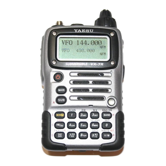
Yaesu VX-7R Operating Manual
50/144/430 mhz triple-band heavy duty submersible transceiver
Hide thumbs
Also See for VX-7R:
- Operating manual (104 pages) ,
- Service manual (64 pages) ,
- Brochure & specs (4 pages)
Table of Contents
Advertisement
Quick Links
See also:
Service Manual
50/144/430 MHz
TRIPLE-BAND HEAVY DUTY
SUBMERSIBLE TRANSCEIVER
O
M
PERATING
ANUAL
VERTEX STANDARD CO., LTD.
4-8-8 Nakameguro, Meguro-Ku, Tokyo 153-8644, Japan
VERTEX STANDARD
US Headquarters
17210 Edwards Rd., Cerritos, CA 90703, U.S.A.
International Division
8350 N.W. 52nd Terrace, Suite 201, Miami, FL 33166, U.S.A.
YAESU EUROPE B.V.
P.O. Box 75525, 1118 ZN Schiphol, The Netherlands
YAESU UK LTD.
Unit 12, Sun Valley Business Park, Winnall Close
Winchester, Hampshire, SO23 0LB, U.K.
VERTEX STANDARD HK LTD.
Unit 5, 20/F., Seaview Centre, 139-141 Hoi Bun Road,
Kwun Tong, Kowloon, Hong Kong
Advertisement
Table of Contents

Related Manuals for Yaesu VX-7R


Summary of Contents for Yaesu VX-7R
- Page 1 17210 Edwards Rd., Cerritos, CA 90703, U.S.A. International Division 8350 N.W. 52nd Terrace, Suite 201, Miami, FL 33166, U.S.A. YAESU EUROPE B.V. P.O. Box 75525, 1118 ZN Schiphol, The Netherlands YAESU UK LTD. Unit 12, Sun Valley Business Park, Winnall Close Winchester, Hampshire, SO23 0LB, U.K.
-
Page 2: Table Of Contents
Introduction ... 1 Controls & Connections ... 2 Display Icons & Indicators ... 3 Keypad Function ... 4 Accessories & Options ... 6 Installation of Accessories ... 7 Antenna Installation ... 7 How to Install the Quick Draw Belt Clip ... 8 Installation of FNB-80LI Battery Pack ... -
Page 3: Introduction
VHF and UHF two- way amateur communications, along with unmatched monitoring capability. The VX-7R’s small size allows you to take it any- where – hiking, skiing, or while walking around town – and its operating flexibility brings the user many avenues of operating enjoyment. -
Page 4: Controls & Connections
KEYBOARD These 17 keys select many of the most important operating features on the VX-7R. This function of the keys are de- scribed in details on pages 4 and 5. VOLUME This control adjusts the audio volume level. -
Page 5: Display Icons & Indicators
: DTMF Autodialer Active (page 39) : Audio Mute Active (page 17) : VOX Active (page 18) : RF Front-end Attenuator Active (page 40) : Battery Saver Active (page 40) : Low Battery! (page 10) VX-7R O PERATING ANUAL ISPLAY CONS “Main” Band Frequency “Main”... -
Page 6: Keypad Function
Frequency entry digit “5” Activates the Smart Search Feature Store the current setting into the Hyper Memory “5” Frequency entry digit “8” Activates the CTCSS or DCS Operation Store the current setting into the Hyper Memory “8” VX-7R O PERATING ANUAL... - Page 7 “9” Memory System Enters the “Special Memory” mode Store the current setting “Memory Tune” mode into the Hyper Memory “9” Memory Recall mode VX-7R O PERATING ANUAL next-highest Press Key frequency band next-lowest Press + frequency band Press and Hold...
-
Page 8: Accessories & Options
Barometric Pressure Sensor Unit Availability of accessories may vary. Some accessories are supplied as standard per local requirements, while others may be unavailable in some regions. Consult your Yaesu Dealer for details regarding these and any newly-available options. Connection of any non-Yaesu- approved accessory, should it cause damage, may void the Limited Warranty on this apparatus. -
Page 9: Installation Of Accessories
Do not over- tighten by use of extreme force. When operating the VX-7R on the 50 MHz band and lower frequencies, disconnect the antenna cap from the base antenna, then screw the Extender Element onto the Antenna Base. Of... -
Page 10: How To Install The Quick Draw Belt Clip
OW TO NSTALL THE 1. Connect the hanger to the rear of the VX-7R, with the notch pointing directly up, using the supplied screw (Figure 1). Use only the screw included with the clip to mount the clip to the back of the VX-7R! 2. -
Page 11: Installation Of Fba-23 (Option) Alkaline Battery Case
¦ The FBA-23 is designed for use only with AA-type Alkaline cells. ¦ If you do not use the VX-7R for a long time, remove the Alkaline batteries from the FBA-23, as battery leakage could cause damage to the FBA-23 and/or the trans- ceiver. -
Page 12: Battery Life Information
AC O PERATION The VX-7R may be operated from your house current by use of the supplied NC-72B/C Battery Charger. The NC-72B/C should only be used for reception, because it is not ca- pable of supplying sufficient current to support transmission. -
Page 13: Interface Of Packet Tncs
The audio level from the receiver to the TNC may be adjusted by using the VOLUME knob, as with voice operation. The input level to the VX-7R from the TNC should be adjusted at the TNC side; the optimum input voltage is approximately 5 mV at 2000 Ohms. -
Page 14: Operation
Hi! I’m R. F. Radio, and I’ll be helping you along as you learn the many features of the VX-7R. I know you’re anxious to get on the air, but I encour- age you to read the “Operation” section of this manual as thoroughly as possible, so you’ll get the most out of this fantastic new transceiver. -
Page 15: Squelch Adjustment
The VX-7R’s Squelch system allows you to mute the background noise when no signal is being received. Not only does the Squelch system make “standby” operation more pleas- ant, it also significantly reduces battery current consumption. The Squelch system may be adjusted independently for the FM and Wide-FM (FM Broad- cast) modes. -
Page 16: Selecting The Operating Band
PERATION ELECTING THE In the factory default configuration, the VX-7R operates in the “Dual Receive” mode. During Dual Receive operation, the “Main” band frequency will be displayed on the upper side of the LCD, and the “Sub” band frequency will be displayed on the lower side, with the “Operating”... -
Page 17: Selecting The Frequency Band
3. The VX-7R uses a dual VFO system (described previously). To switch TX/RX opera- tion from the “Main” VFO to the “Sub” VFO instantly, press the key will return the VX-7R to the “Main” VFO. The frequency band Pressing the bearing the “Large”... -
Page 18: Frequency Navigation
PERATION The VX-7R will initially be operating in the “VFO” mode, as just described. This is a channelized system which allows free tuning throughout the currently-selected operating band. Three basic frequency navigation methods are available on the VX-7R: 1 ) Tuning Dial (Outer ring of dual control on Top Panel) Rotation of the DIAL allows tuning in the pre-programmed steps established for the cur- rent operating band. -
Page 19: Audio Muting
VFO MODE ) must be set to “BAND.” In other words, the BAND Link feature cannot activated if “Main” band and “Sub” band are not set to the same band, or if Menu Item ( Misc Setup #10: VFO MODE ) is set to “ALL.” VX-7R O PERATING ANUAL... -
Page 20: Transmission
Once you have set up an appropriate frequency inside one of the three (or four) Amateur bands on which the VX-7R can transmit (50 MHz, 144 MHz, or 430 MHz, plus 222 MHz on the USA version), you’re ready to transmit. These are the most basic steps; more ad- vanced aspects of transmitter operation will be discussed later. -
Page 21: Vox Operation
2 ) When you are operating on one of the Low power settings, you can press the then press the PTT switch, to cause the VX-7R to transmit (temporarily) on High power. After one transmission, the power level will revert to the previously-selected Low power setting. -
Page 22: Am Broadcast Reception
Reception of AM signals in the aeronautical band (108-137 MHz) is similar to that de- scribed in the previous section. 1. Be sure that the VX-7R is set to the VFO mode on the “Main” band. 2. Press the key (or press you see a frequency in the aeronautical band. -
Page 23: Fm Broadcast/Tv Audio Reception
The VX-7R also includes provision for reception in the FM broadcast band, utilizing a wide-bandwidth filter which provides excellent fidelity. To Activate FM Broadcast Reception 1. Be sure that the VX-7R is set to the VFO mode on the “Main” band. 2. Press the key (or press a frequency in the FM broadcast band appears on the dis- play. -
Page 24: Weather Broadcast Reception
PERATION EATHER The VX-7R includes a unique feature which allows reception of weather broadcasts in the 160-MHz frequency range. Ten standard Weather Broadcast channels are pre-loaded into a special memory bank. To listen to a Weather Broadcast Channel or VHF Marine Channel: 1. -
Page 25: Keyboard Locking
In order to prevent accidental frequency change or inadvertent transmission, various as- pects of the VX-7R’s keys and switches may be locked out. The possible lockout combina- tions are: KEY: Just the front panel keys are locked out DIAL: Just the top panel DIAL is locked out... -
Page 26: Keypad/Lcd Illumination
PERATION Your VX-7R includes a reddish illumination lamp which aids in nighttime operation. The red illumination yields clear viewing of the display in a dark environment, with minimal degradation of your night vision. Three options for activating the lamp are provided: KEY Mode: Illuminates the Keypad/LCD for 5 seconds when any key pressed. -
Page 27: Advanced Operation
20/25/50/100 kHz per step, any number of which may be important to your operating requirements. The VX-7R is set up at the factory with different default steps on each oper- ating band which probably are satisfactory for most operation. However, if you need to change the channel step increments, the procedure to do so is very easy. -
Page 28: Changing The Operating Mode
PERATION HANGING THE The VX-7R provides for automatic mode changing when the radio is tuned to different operating frequencies. However, should an unusual operating situation arise in which you need to change between the available operating modes (FM-Narrow, FM-Wide, and AM), here is the procedure for doing so: 1. -
Page 29: Repeater Operation
Repeater Shifts Your VX-7R has been configured, at the factory, for the repeater shifts customary in your country. For the 50 MHz band, this usually will be 1 MHz, while the 144 MHz shift will be 600 kHz; on 70 cm, the shift may be 1.6 MHz, 7.6 MHz, or 5 MHz (USA version). -
Page 30: Manual Repeater Shift Activation
If you just have one “odd” split that you need to program, don’t change the “default” repeated shifts using this Menu Item! Enter the transmit and re- ceive frequencies separately, as shown on page 46. EPEATER PERATION key to enter the Set mode. key to enter the Set mode. VX-7R O PERATING ANUAL... - Page 31 “HM” (for instant switching to the “Home” chan- nel for the band you are operating on). To change the configuration of this key, use Menu Item ( Misc. Setup #2 HOM/REV ) . See page 49. VX-7R O PERATING ANUAL...
-
Page 32: Ctcss Operation
“TONE.” When “TONE SQL” appears, this means that the Tone SQueLch system is active, which mutes your VX-7R’s receiver until it receives a call from an- other radio sending out a matching CTCSS tone. This can help keep your radio quiet until a specific call is received, which may be helpful while operating in congested areas. -
Page 33: Dcs Operation
CTCSS. The DCS Encoder/Decoder is built into your VX-7R, and operation is very similar to that just described for CTCSS. Your repeater system may be configured for DCS;... -
Page 34: Tone Search Scanning
When you release the MONI key, Tone Scanning will resume after about a second. Tone Scanning works either in the VFO or Memory modes. EARCH CANNING key to enter the Set mode. key to start scanning key to lock in that tone/code, then press VX-7R O PERATING ANUAL... -
Page 35: Ctcss/Dcs Bell Operation
CTCSS/DCS B During CTCSS Decode or DCS operation, you may set up the VX-7R such that a ringing “bell” sound alerts you to the fact that a call is coming in. Here is the procedure for activat- ing the CTCSS/DCS Bell: 1. -
Page 36: Tone Calling (1750 Hz)
1750-Hz audio tone will be superimposed on the carrier. Once access to the repeater has been gained, you may release the MONI key, and use the PTT key for activating the transmitter. ( 1750 H ALLING key to enter the Set mode. VX-7R O PERATING ANUAL... -
Page 37: Arts (Automatic Range Transponder System)
3. Every 25 seconds, your radio will transmit a “polling” call to the other station. When that station responds with its own ARTS polling signal, the display will change to “IN RANGE” to confirm that the other station’s polling code was received in response to yours. VX-7R O PERATING ANUAL DVANCED... - Page 38 4. When you have made your selection, press the PTT key to save the new setting and exit to normal operation. ANGE RANSPONDER key to exit ARTS operation and resume normal key to enter the Set mode. key to enter the Set mode. VX-7R O YSTEM PERATING ANUAL...
- Page 39 PTT key to save the settings and exit to normal operation. You may check your work by monitoring the entere callsign. To do this, repeat steps 1 - 3 above, then press the VX-7R O PERATING ANUAL...
-
Page 40: Dtmf Operation
DVANCED PERATION The VX-7R’s 16-button keypad allows easy DTMF dialing for Autopatch, repeater con- trol, or Internet-link access purposes. Besides numerical digits [0] through [9], the keypad includes the [*] and [#] digits, plus the [A], [B], [C], and [D] tones often used for repeater control. -
Page 41: Emergency Channel Operation
PTT key, as the transmitter will be held “on the air” until the DTMF string is completed. MERGENCY The VX-7R includes an “Emergency” feature which may be useful if you have someone monitoring on the same frequency as your transceiver’s UHF “Home” channel. See page 47 for details on setting the Home channel. -
Page 42: Att (Front End Attenuator)
ECEIVE An important feature of the VX-7R is its Receive Battery Saver, which “puts the radio to sleep” for a time interval, periodically “waking it up” to check for activity. If somebody is talking on the channel, the VX-7R will remain in the “active” mode, then resume its “sleep”... -
Page 43: Tx Battery Saver
The VX-7R also includes a useful Transmit Battery Saver, which will automatically lower the power output level when the last signal received was very strong. For example, when you are in the immediate vicinity of a repeater station, there generally is no reason to use the full 5 Watts of power output in order to achieve full-quieting access to the repeater. -
Page 44: Automatic Power-Off (Apo) Feature
Set mode. ” icon will appear at the ( PWR ) switch for 2 seconds to turn the transceiver back on IMER key to enter the Set mode. VX-7R O EATURE ( TOT ) PERATING ANUAL... -
Page 45: Busy Channel Lock-Out (Bclo)
(thus activating the MIC Monitor feature). The VX-7R exit from the Set mode. 5. The VX-7R’s internal microphone will now pick up the sound around the transceiver, then output its to the VC-27 Earpiece/Microphone. 6. To disable the MIC Monitor feature, repeat steps 2 - 4, pressing the select “OFF,”... -
Page 46: Changing The Tx Deviation Level
In such operating environments, it often is required that operators use reduced deviation levels, so as to reduce the potential for interference to users on adjacent channels. The VX-7R includes a simple method of accomplishing this: 1. Press the key, then press the 2. - Page 47 The VX-7R provides a wide variety of memory system resources. These include: r Regular Memory Channels, which made up of: ¦ 450 “Standard” memory channels, numbered “1” through “450.” ¦ 12 (USA version) or 11 (EXP version) Home channels, providing storage and quick recall of one prime frequency on each operating band.
-
Page 48: Memory Mode
1/2 second. key, rotate the DIAL to select the desired key, rotate the DIAL to select the same memory ” indication will appear in the display. . VX-7R O PERATION key for 1/2 key once more momentarily PERATING... -
Page 49: Memory Storage
5. To recall the HOME channel, press the ing either in the VFO or MR mode. Note that the UHF HOME channel is the one used during “Emergency” opera- tion. See page 39 for details regarding this feature. VX-7R O PERATING ANUAL EMORY... -
Page 50: Labeling Memories
The alphanumeric Tag does not appear if you activate the Dual Receive Operation. EMORY HANNEL key to enter the Set mode. key, then press the key repeatedly to toggle among the seven available charac- VX-7R O PERATION key to select any of the 61 PERATING ANUAL... -
Page 51: Memory Offset Tuning
Once you have recalled a particular memory channel, you may easily tune off that channel, as though you were in the “VFO” mode. 1. With the VX-7R in the “MR” (Memory Recall) mode, select the desired memory chan- nel. 2. Now press and hold in the placed by one which says “MT”... -
Page 52: Masking Memories
Use the “next available memory” tech- nique (look for the [ Û ] icon) storage technique to avoid over-writing a masked memory. EMORY HANNEL key for 1/2 second, then rotate the DIAL to select the memory VX-7R O PERATION PERATING ANUAL... -
Page 53: Memory Group Operation
8. To change the Memory Group to another Group, press the rotate the DIAL knob. 9. To exit from Memory Group operation, recall the Special Memory Menu (press ) then change its setting to “1 OFF.” VX-7R O PERATING ANUAL EMORY... -
Page 54: Moving Memory Data To The Vfo
To place the radio into the Memory Only mode, turn the radio off. Now press and hold in key while turning the radio on. To return to normal operation, repeat the above power-on procedure. key for 1/2 second, then press the VX-7R O key. The data will PERATING ANUAL... -
Page 55: Hyper Memory Operation
The VX-7R usually stores, into memory, the operating frequency and some aspects of operating status (such as CTCSS/DCS data, repeater shift, power level etc.). However, the “Hyper Memory” Mode allows you to store the total current configuration of the radio into a special “Hyper”... -
Page 56: One-Touch Memory Operation
One-Touch Memory locations, by repeating the above process. One-Touch Memory Recall 1. Set the VX-7R to Mono band operation on the “Main” band. 2. Press the key, then press the 3. Rotate the DIAL knob to select the “3 OTM” mode. -
Page 57: Sort-Wave Broadcast Station Memory Channels
WAVE The Short-wave Broadcast Station Memory Channel Bank has been pre-programmed at the factory, for quick selection of broadcast stations. 1. Set the VX-7R to Mono band operation on the “Main” band. 2. Press the key, then press the Special Memory Menu. -
Page 58: Vhf Marine Memory Channels
EMORY VHF M The VHF Marine Channel Bank has been pre-programmed at the factory, for quick selec- tion. 1. Set the VX-7R to Mono band operation on the “Main” band. 2. Press the key, then press the Special Memory Menu. -
Page 59: Scanning
The VX-7R allows you to scan just the memory channels, the entire operating band, or a portion of that band. It will halt on signals encountered, so you can talk to the station(s) on that frequency, if you like. Scanning operation is basically the same in each of the above modes. Before you begin, take a moment to select the way in which you would like the scanner to resume scanning after it halts on a signal. -
Page 60: Vfo Scanning
5. To cancel scanning, press the PTT or When you start scanning, the VX-7R will be changing frequency in the up- ward direction. If you want to change direction of the scan while it is under- way, rotate the DIAL one click in the opposite direction (in this case, one click counter-clockwise). -
Page 61: Temporary Memory Skip
5 above (the “Skipped” channel will, of course, still be accessible via manual channel selection methods using the DIAL in the MR mode, whether or not it is locked out of the scanning loop). VX-7R O PERATING ANUAL... -
Page 62: Preferential Memory Scan
CANNING Preferential Memory Scan The VX-7R also allows you to set up a “Preferential Scan List” of channels which you can “flag” within the memory system. These channels are designated by a “ ” icon when you have selected them, one by one, for the Preferential Scan List. When you initiate memory scanning on a channel with the “... -
Page 63: Programmable (Band Limit) Memory Scan (Pms) . 61 "Priority Channel" Scanning (Dual Watch)
(for the “Main” band priority channel) or “p” icon (for the “Sub” band priority chan- nel) will appear to the right of the “MR” icon, indicating it is the Priority channel. 3. Now set the VX-7R for operation on another memory channel, or on a VFO frequency. 4. Press the... -
Page 64: Automatic Lamp Illumination On Scan Stop
CANNING UTOMATIC The VX-7R will automatically illuminate the LCD Lamp whenever the scanner stops on a signal; this allows you to see the frequency of the incoming signal better at night. Note that this will, of course, increase the battery consumption, so be sure to switch it off during the day (the default condition for this feature is “ON”). -
Page 65: Spectrum Analyzer Operation
The display indicates the relative signal strength on channels immediately adjacent to the current operating frequency. The Spectrum Analyzer feature can only be activated while the VX-7R is operat- ing in the Mono band mode. Two basic operating modes for Spectrum Analyzer are available: In this mode, the transceiver sweeps the current band once. -
Page 66: Smart Search Operation
One-Shot searching; if all 31 channels are not filled after the first sweep, however, the radio will continue sweeping until they are all filled. The Smart Search feature can only be activated while the VX-7R is operating in the Mono band mode. - Page 67 7. To return to normal operation, press the Smart Search is a great tool when visiting a city for the first time. You don’t need to spend hours looking up repeater frequencies from a reference guidebook…just ask your VX-7R where the action is! VX-7R O PERATING...
-
Page 68: Channel Counter Operation
The VX-7R performs a high-speed search within a ±5 MHz range from the frequency displayed on the LCD. When the strongest signal in that range is identified, the VX-7R displays the frequency of that (strongest) signal, and writes it into the special “Channel Counter”... -
Page 69: Internet Connection Feature
The VX-7R can be used to access the repeater which provide the Vertex Standard WIRES (Wide-Coverage Internet Repeater Enhancement System). 1. Press the key to activate the Internet Connection feature. The “ appear in the upper left corner of the display. -
Page 70: Sensor Mode
If you are at sea level, of course, the latter parameter requires no research. The Sensor mode can only display while the VX-7R is operating in the Mono band mode (except the Weather Forecast mode). The internal sensor mea- sures continuously unless the Sensor mode is disabled. -
Page 71: Sensor Mode Option
3 ) The VX-7R’s Weather Forecast feature is designed to be a supplemental aid for the information of the user. It must not be relied upon as a primary weather forecasting tool, and Vertex Standard is not responsible for any damage or other liability arising from its use. -
Page 72: Selecting The Wave Form Display
Menu Item. 4. Press the key to indicate the barometer data in “hpa” units. key to adjust the VX-7R display to the calibrated barometer 5. Press the value in the “hpa” units. 6. Press the key to save the new setting. -
Page 73: Selecting The Unit Of Altimeter
4. Press the key to indicate the altimeter data in “m” units. 5. Press the key to adjust the VX-7R display to the true altitude at your current location in “m” units. 6. Press the key to save the new setting. -
Page 74: Timer Operation
IMER PERATION The VX-7R includes the capability to turn itself on/off at preset time. If you use these features, you must first set the VX-7R’s clock, as described previously. 1. Press the key, then press the 2. Rotate the DIAL to select the Menu Item labeled (Save Modes #5: ON TIMER). -
Page 75: Display Customization
The VX-7R’s display includes several unique customization options which can expand your enjoyment of your transceiver. The display’s alphanumeric labels can be replaced by pictorial icons, which may be easier to remember during operation. To activate the Icon mode: 1. Press the key, then press the 2. -
Page 76: Icon Editor
ISPLAY USTOMIZATION The VX-7R has three Icon memory channels which may be customized by the user. Using this feature, you may draw new Icons to be used in identifying features in a way easily recognizable by you. 1. Press the key, then press the 2. -
Page 77: Power-Off Display Mode
When the VX-7R is turned off, the LCD may be set up to display one or more environmen- tal measurements. These include temperature, barometric pressure, altitude, or combina- tions of these. 1. Press the key, then press the 2. Rotate the DIAL to select the Menu Item labeled (Display Setup #4: DISPLAY MODE). -
Page 78: S-And Tx Power Meter Symbols
ISPLAY USTOMIZATION The VX-7R has six types of S- (Signal Strength) and TX Power Meter symbol formats available. You may change the default setting to any of the available symbols. 1. Press the key, then press the 2. Rotate the DIAL to select the Menu Item labeled (Display Setup #8: METER SYMBOL). -
Page 79: Font Editor
The VX-7R has five Font memory channels which may be created the user. 1. Press the key, then press the 2. Rotate the DIAL to select the Menu Item labeled (Misc Setup #11: FONT EDITOR). 3. Press the key to enable this Menu Item. -
Page 80: Display Contrast
4. When you have completed the adjustment, press the PTT key to save the new setting and exit to normal operation. ISPLAY ONTRAST key to enter the Set mode. ISPLAY IMMER key to enter the Set mode. VX-7R O PERATING ANUAL... -
Page 81: Strobe Customization
STROBE C The VX-7R’s STROBE also includes customization options. COLOR Selection 1. Press the key, then press the 2. Rotate the DIAL to select the Menu Item labeled (Display Setup #7: LED COLOR 2). 3. Press the key to enable modification of this Menu Item. -
Page 82: Reset Procedures
Set (Menu) mode settings to their factory defaults (press any other key to cancel the Reset procedure). ESETTING , and keys while turning the radio on. ESETTING , and keys while turning the radio on. VX-7R O PERATING ANUAL... -
Page 83: Cloning
The VX-7R includes a convenient “Clone” feature, which allows the memory and configu- ration data from one transceiver to be transferred to another VX-7R. This can be particu- larly useful when configuring a number of transceivers for a public service operation. Here is the procedure for Cloning one radio’s data to another:... -
Page 84: Set Mode
The VX-7R Set (Menu) mode, already described in parts of many previous chapters, is easy to activate and set. It may be used for configuration of a wide variety of transceiver parameters, some of which have not been detailed previously. Use the following procedure to activate the Set (Menu) mode: 1. - Page 85 #18 [ATT] Enables/disables the Front-end Attenuator #19 [MIC MONITOR] Enables/disables the Microphone Monitor feature. #20 [WX ALERT] Enables/disables the Weather Alert Feature ø1: Depends on the Frequency Band. VX-7R O PERATING ANUAL ø2 ø2 ø2 ø2: Requires optional SU-1 ø3: Depends on the Transceiver Version.
- Page 86 Basic Setup #8 [ MUTE SET ] Function: Enables/disables the Audio Mute feature while using Dual Band reception. Available Values: ON/OFF Default: OFF Basic Setup #9 [ KEY BEEP ] Function: Enables/disables the Keypad beeper. Available Values: ON/OFF Default: ON VX-7R O PERATING ANUAL...
- Page 87 Display Setup #2 [ CONTRAST ] Function: Setting of the Display contrast level. Available Values: 1 ~ 10 Default: 7 Display Setup #3 [ DIMMER ] Function: Setting of the Display brightness level. Available Values: 1 ~ 12 Default: 10 VX-7R O PERATING ANUAL...
- Page 88 Blue color hue may be performed, on a numeri- cal scale of 0 to 255. See page 79 for details. Default LED No. COLOR Green Blue Orange Purple Sky Blue Yellow Green Millky White Violet White VX-7R O PERATING ANUAL...
- Page 89 TSQ/DCS/DTMF #1 [ SQL TYPE ] Function: Selects the Tone Encoder and/or Decoder mode. Available Values: OFF/TONE/TONE SQL/DCS Default: OFF TONE: CTCSS Encoder TONE SQL:CTCSS Encoder/Decoder DCS: Digital Coded Squelch Encoder/Decoder VX-7R O PERATING ANUAL key to enable the setting of the “STROBE” color, ,...
- Page 90 114.8 131.8 136.5 141.3 159.8 162.2 165.5 177.3 179.9 183.5 196.6 199.5 203.5 225.7 229.1 233.6 – – – DCS CODE – – – – – VX-7R O PERATING ANUAL 79.7 97.4 118.8 146.2 167.9 186.2 206.5 241.8 – –...
- Page 91 Function: Enables/disables the Band-edge beeper while selecting the frequency by the DIAL. Available Values: ON/OFF Default: OFF When this Menu Item is set to “ON,” a beep will sound when the frequency reaches the band edge while selecting the VFO frequency by the DIAL. VX-7R O PERATING ANUAL...
- Page 92 The scanner will hold until the signal disappears, then will resume when the carrier drops. The scanner will stop when a signal is received, and will not restart. VX-7R O PERATING ANUAL...
- Page 93 Measurement #7 [ ALTITUDE OFFSET ] Function: Correcting the Altimeter (requires optional SU-1). See page 71 for details. Save Modes #1 [ APO ] Function: Setting of the Automatic Power-Off time. Available Values: OFF/30 min/1 hour/3 hours/5 hours/8 hours Default: OFF VX-7R O PERATING ANUAL...
- Page 94 ARTS #2 [ ARTS INTERVAL ] Function: Select the Polling Interval during ARTS operation. Available Values: 15 SEC/25 SEC Default: 25 SEC This setting determines how often the other station will be polled during ARTS operation. VX-7R O PERATING ANUAL...
- Page 95 MONI: Pressing the MONI key causes the Noise/Tone Squelch to be over-ridden, allow- ing you to listen for weak (or non-encoded) signals. T-CAL: Pressing the MONI key activates a 1750-Hz burst tone, used for repeater access in many countries. VX-7R O PERATING ANUAL key. .
- Page 96 Loud “Alarm” sounds along with flashing of the STROBE in sequential colors. Loud “Alarm” sounds. Flashes the STROBE in sequential colors. Continuation changes the STROBE in sequential colors. 4: Medium flashing, 5: Rapid flashing) The STROBE glows continuously in white. VX-7R O key to PERATING ANUAL...
- Page 97 Available Values: ON/OFF Default: OFF Misc Setup #13 [ ICON EDITOR ] Function: Editing of the User Icon. See page 74 for details. Misc Setup #14 [ ICON SELECT ] Function: ICON selection. See page 73 for details. VX-7R O PERATING ANUAL...
- Page 98 Misc Setup #19 [ MIC MONITOR ] Function: Enables/disables the Microphone Monitor feature. Available Values: ON/OFF Default: OFF Misc Setup #20 [ WX ALERT ] Function: Enables/disables the Weather Alert Feature Available Values: ON/OFF Default: OFF VX-7R O PERATING ANUAL...
-
Page 99: Installation Of The Su-1
The Barometric Pressure/Altitude features of the optional SU-1 are designed to be supplemental aids for the information of the user, and are not intended to be a substitute for accurate, calibrated Barometer or Altimeter devices used for naviga- tion critical to personal safety. VX-7R O PERATING ANUAL Important note... -
Page 100: Specifications
Weight (Approx.): 260 g (9.2 oz) with FNB-80LI & antenna 50-54 MHz 137-174 MHz 420-470 MHz 50-54 MHz (MAIN & SUB) 144-146 MHz or 144-148 MHz (MAIN & SUB) 222-225 MHz ((MAIN, USA version) 430-440 MHz or 430-450 MHz (MAIN & SUB) VX-7R O PERATING ANUAL... - Page 101 AF Output: 200 mW @ 8 Ohms for 10 % THD (@ 7.4 V DC) 400 mW @ 8 Ohms for 10 % THD (@ 13.8 V DC) Specifications are subject to change without notice, and are guaranteed within the 50/144/222/ 430 MHz amateur bands only. VX-7R O PERATING ANUAL 1st: 47.25 MHz (N-FM, AM), 45.8 MHz (W-FM)
-
Page 102: Appendix
“repeater in the sky” transponder, affording low-power stations the opportunity to make contacts with other stations thousands of miles away. Communication generally is most easily possible when using a hand-held transceiver (like the VX-7R) in conjunction with a small beam antenna, so as to improve your uplink signal. - Page 103 1. Changes or modifications to this device not expressly approved by VERTEX STANDARD could void the user’s authorization to operate this device. 2. This device complies with part 15 of the FCC Rules. Operation is subject to the following two conditions; (1) this device may not cause harmful interference, and (2) this device must accept any interference including interference that may cause undesired operation.
- Page 104 Copyright 2002 Printed in Japan VERTEX STANDARD CO., LTD. All rights reserved. No portion of this manual may be reproduced without the permission of E H 0 0 9 M 1 0 1 VERTEX STANDARD CO., LTD. 0204L-AY...