
Related Manuals for Comelit Quadra Series


Summary of Contents for Comelit Quadra Series
- Page 1 People PL8461V F U L L T E C H N I C A L M A N U A L Join us in taking care of our planet...
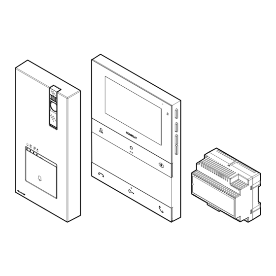
- Page 2 | Table of contents | Quadra and Hands-free People Kit art. PL8461V for Simplebus 2 system Single-family kit consisting of Quadra series entrance panel art. 4893M and 4.3” hands-free door People series entry monitor art. PL6721 for Simplebus 2 system. The entrance panel is supplied with call buttons to expand the kit for up to 4 residences.
- Page 3 | Table of contents | Table of contents Kit art. PL8461V Notes for the installer Art. 4893M Description Technical specifications Installation Programming Art. 1209 Description Technical specifications Art. PL6721 Description Technical specifications Programming the user code Installation Programming Operating distances Wiring diagrams System expansion diagrams Using the entrance panel relay on generic actuator control...
- Page 4 | Table of contents | Kit art. PL8461V The kit components are supplied pre-programmed to work as a single-family setup. PL6721 PL8461V 1209 4893M 1214/2C 1216 The door entry monitor has an NFC connection which means it can be programmed quickly and easily via the MyComelit app, available to download free of charge.
- Page 5 | Table of contents | Notes for the installer 72° 72° 72° 50 cm 50 cm 50 cm 92 cm 85° The camera must not be installed in front of light sources, or in places where the filmed subject is against the light.
- Page 6 Art. 4893M Description Wall-mounted external unit for Quadra series door entry monitor. Die-cast aluminium front panel, wide-angle colour video camera and single LED for lighting at night. Mechanical buttons with the option of setting 1 to 4 call buttons via DIP-switch. Indicator LED for call sent, lock-release activated, audio activated and system busy.
- Page 7 | Table of contents | 8. DIP-SWITCH for function programming. 9. PR programming input/output switch. CNF programming confirmation switch. 10. Terminal block M1: LL bus line connection. RTE request to exit button input. COM common input for RTE and DO contacts. DO door open indication input.
-
Page 8: Technical Specifications
| Table of contents | Technical specifications GENERAL DATA Type Complete unit Height (mm) 195 Width (mm) 95 Depth (mm) 28 Product weight (g) 300 Product colour Grey RAL 9006, Black RAL9005 Surface mounting Yes COMPATIBLE SYSTEMS Simplebus 2 audio/video kit with power supply unit art. -
Page 9: Installation
| Table of contents | Installation OPEN You can download the free software (art. 1235A) to print the entrance panel name cards, using the adhesive pre-cut sheets available in our catalogue (art. 1217A). - Page 10 | Table of contents | Before securing the screw, make sure that you do not need to program the external unit and make sure that the metal front panel does not rub against other metal parts, with consequent risk of damage to its insulating coating. While the system is running, take care not to accidentally call users when replacing the nameplate labels.
-
Page 11: Changing Nameplates
| Table of contents | CHANGING NAMEPLATES... - Page 12 | Table of contents | Programming ENTRANCE PANEL SETTINGS f Permanently set the S1 DIP-switches corresponding to the function you want to program in accordance with the table below (you do not need to enter programming mode) FUNCTION The SE output and the C-NO relay are controlled by 2 separate buttons on the door entry monitor: the key button (SE) and the generic actuator button (C-NO) 1 2 3 4...
- Page 13 | Table of contents | PROGRAMMING CALL CODES FOR TWO-FAMILY AND FOUR-FAMILY VERSION f Take note of the DIP-switch settings. f Set the code corresponding to the desired programming. 1 2 3 4 default 1 2 3 4 1 2 3 4...
- Page 14 | Table of contents | f Reset the DIP-switch settings.
- Page 15 | Table of contents | PROGRAMMING AN ADDITIONAL ENTRANCE PANEL With switching device art. 1405, only one additional entrance panel may be installed. The two entrance panels must be programmed as main and secondary ; see table below. • The “Main entrance panel” carries out lock-release (or actuator) commands only when it is in call or self activation status.
- Page 16 | Table of contents | f Reset the DIP-switch settings.
-
Page 17: Programming A Generic Call Address
| Table of contents | PROGRAMMING A GENERIC CALL ADDRESS f Make a note of the DIP-switch settings f Set the call code of the apartment you wish to call (see Table of user codes) example code 2 1 2 3 4... -
Page 18: Restore Default
| Table of contents | RESTORE DEFAULT f Take note of the DIP-switch settings. f Set the DIP-switches to position 254 (ON 2, 3, 4, 5, 6, 7, 8) 1 2 3 4 f Reset the DIP-switch settings. - Page 19 | Table of contents | Art. 1209 Description 33 VDC power supply unit for Simplebus 2 KIT, for direct connection to the external unit and internal unit. Equipped with overload and short circuit protection. Input voltage 110-240 VAC. Dimensions: 106 x 62 x 89 mm (6 DIN modules).
-
Page 20: Main Features
| Table of contents | Technical specifications MAIN FEATURES Power supply voltage 110-240 VAC Max. current delivered (A) Applicable to DIN rail Number of DIN modules GENERAL DATA Height (mm) Width (mm) Depth (mm) Coating material type Plastic Product colour White Operating temperature (°C) -5 to 40... - Page 21 | Table of contents | Art. PL6721 Description People series colour door entry monitor for Simplebus 2 system Hands-free version with 4.3” / 16:9 screen. The door entry monitor can be programmed, even when switched off, via smartphone using the MyComelit app, which is available to download free of charge.
- Page 22 | Table of contents | 7. Speaker. 8. Dip-switch for programming the user code. 9. CV5 Jumper for video closure. 10. Pin for securing the terminal block.
- Page 23 | Table of contents | FRONT BUTTONS - FACTORY PROGRAMMING Call to standard switchboard (not available in KIT systems) f Press the button to send a call to the porter switchboard. Generic actuator f Press the button to activate a generic actuator (art. 1256) or the relay for the external entrance panel.
-
Page 24: Side Buttons
| Table of contents | SIDE BUTTONS Button for activating “Silent mode” Confirm button Menu access and navigation button Buttons for scrolling menus and selecting values ACTIVATING “SILENT MODE” f Press the button to activate/deactivate Silent mode. » The red LED indicates that the function is active. ACCESSING AND NAVIGATING MENUS f Press one of the following buttons to access the user menu. -
Page 25: Indicator Leds
| Table of contents | INDICATOR LEDS Red LED Flashing: communication taking place. Flashing: incoming call/communication taking place. Flashing with door entry monitor in standby: “Door open” indication. White LED Lit steadily with door entry monitor in standby: “Automatic lock-release on receipt of call”... - Page 26 | Table of contents | Technical specifications 135 mm 23 mm GENERAL DATA Product colour White RAL9003, Black RAL9005 Surface mounting Yes Desk base mounting Yes, with specific accessory Product weight 430 grams Coating material type ABS, PMMA COMPATIBLE SYSTEMS Simplebus 2 audio/video with power supply unit art.
-
Page 27: General Features
| Table of contents | ENVIRONMENTAL AND CONFORMITY SPECIFICATIONS IP protection rating IP30 Operating temperature (°C) 5 ‐ 40 ° Operating humidity (max. RH) 25 - 75 % Environmental class I RoHS II - 2011/65/EU (EN IEC 63000:2018), EMC 2014/30/EU (EN 61000-6- CE certification 1:2007, EN 61000-6-3:2007+A1:2011) GENERAL FEATURES... - Page 28 | Table of contents | Programming the user code The door entry monitor included in the kit is pre-programmed with user code 1. The user code must be programmed on any additional door entry monitors via the MyComelit app or using the dip-switches.
- Page 29 | Table of contents | 3. Enter the desired user code and press “WRITE”. User code User code MyComelit user code user code user code WREITE WRITE Bring your smartphone close to the door entry monitor 4. Bring your smartphone close to the NFC detection area of the door entry monitor (identified by its label) and make a circular motion until you feel it vibrate.
- Page 30 | Table of contents | if you want to program the user codes for other door entry monitors in sequence: 5.B Press "CONTINUE". Configuration complete! CONTINUA CONTINUE 6.B Select the desired increment interval. MyComelit MyComelit user code user code Select an increment* 7.B Bring your smartphone close to the NFC detection area of the new door entry monitor (identified by its label) and make a circular motion until you feel it vibrate.
- Page 31 | Table of contents | PROGRAMMING THE USER CODE USING THE DIP-SWITCHES f Set the DIP-switches to ON to program a user code on the door entry monitor, as per Table of user codes. Example: code 4.
- Page 32 | Table of contents | Installation Fixing points for use when installing in compatible boxes CLACK...
- Page 33 | Table of contents | DISASSEMBLING THE DOOR ENTRY MONITOR REMOVING AND FITTING THE CONNECTION TERMINALS CLACK...
- Page 34 | Table of contents | Programming The programmable buttons are supplied factory programmed with the following functions: [CCS] [ACTG] [AI] [AP] Call to standard Generic actuator Self activation Lock-release switchboard (not available in Kit systems) The programming of these buttons can be customised: •...
- Page 35 | Table of contents | PROGRAMMING VIA INSTALLER MENU The function associated with the buttons can be changed via the installer menu. 1. Press one of the following buttons to access the user menu. 2. Press for 5 sec to access the installer menu. 5 sec »...
- Page 36 | Table of contents | EXAMPLE: PROGRAMMING THE INTERCOM FUNCTION ON THE BUTTON 1. Press one of the following buttons to access the user menu. 2. Press for 5 sec to access the installer menu. » A confirmation tone will sound and the programming screen will appear.
- Page 37 | Table of contents | PROGRAMMING VIA MYCOMELIT APP √ Update the MyComelit App to the latest available version. The MyComelit app can be used to program the door entry monitor quickly and easily, even while it is switched off. The MyComelit app makes it possible to: •...
-
Page 38: Intercom Function
| Table of contents | MAIN AND SECONDARY DOOR ENTRY MONITOR In systems with power supply unit art. 1209, 1 main door entry monitor and 3 secondary door entry monitors can be programmed per apartment. On receipt of a call from the entrance panel: »... - Page 39 | Table of contents | • Selective group intercom This is an intercom call to groups of several door entry monitors in the same apartment or another apartment identified by a dedicated intercom code, different from the user code. The door entry monitor button can be programmed with up to 3 different intercom codes to which the call will be made at once.
-
Page 40: Operating Distances
1209 4893M 4893M A MAX B MAX E MAX Art. 1216 Comelit Art. 4577/4579 1 mm² (Ø 1.2 mm AWG 200 m 100 m (655 feet) (330 feet) UTP5 cat. 5 0.2 mm² (Ø 0.5 mm AWG 24) 100 m... -
Page 41: Wiring Diagrams
| Table of contents | Wiring diagrams PL6721 CFP CFP 110-240V 1209 4893M 12 VAC/VDC 18 Ω MAX Max. 20 m. Local door-opener button. - Page 42 | Table of contents | 1216 PL6721 CFP CFP PL6721 1214/2C CFP CFP PL6721 1214/2C CFP CFP PL6721 1214/2C CFP CFP 1214/2C PL8461V 110-240V 1209 4893M 12 VAC/VDC 18 Ω MAX Max. 20 m. Local door-opener button.
- Page 43 | Table of contents | System expansion diagrams PL6721 1216 CFP CFP 1214/2C 20 m max PL6721 PL6721 CFP CFP CFP CFP 1214/2C In systems with power supply unit art. 1209, a maximum of 1 main door entry monitor (P) and 3 secondary door entry monitors (S) can be programmed for each apartment.
- Page 44 | Table of contents | VIDEO ENTRY SYSTEM RISER 1209 L1 L1 L2 L2 110-240V 1405 4893M 12 VAC/VDC 18 Ω MAX 4893M 12 VAC/VDC 18 Ω MAX To program the entrance panel as Main or Secondary, refer to Programming an additional entrance panel. Max 20 m.
- Page 45 | Table of contents | Max 20 m. Local door-opener button. The door open indication function is not available. The self activation function is available (with toggle function between 2 external units).
- Page 46 | Table of contents | Using the entrance panel relay on generic actuator control 1209 12V/24V AC-DC 4A MAX 1 2 3 4 4893M “C.NC.NO relay activation time: 2 sec.” (default) f Set DIP switch 1 to ON permanently (as shown in the figure, see Entrance panel settings on page 12).
- Page 47 | Table of contents | Table of user codes code DIP ON 1,2,3,4,5 1,3,4,5,6 1,2,4,5,7 1,4,5,6,7 1,2,3,5,8 1,3,5,6,8 1,2,5,7,8 2,3,4,5,6 3,4,5,7 2,4,5,6,7 4,5,8 2,3,5,6,8 3,5,7,8 1,2,3,4,5,6 1,3,4,5,7 123 1,2,4,5,6,7 153 1,4,5,8 183 1,2,3,5,6,8 213 1,3,5,7,8 2,3,4,5,7 3,4,5,6,7 2,4,5,8 4,5,6,8 2,3,5,7,8 1,2,6 95 1,2,3,4,5,7 125 1,3,4,5,6,7 155 1,2,4,5,8...
- Page 48 C E R T I F I E D M A N A G E M E N T S Y S T E M S w w w . c o m e l i t g r o u p . c o m 1st edition 09/2023 Via Don Arrigoni, 5 - 24020 Rovetta (BG) - Italy code 2G40003169...