
Related Manuals for Comelit 4893M


Summary of Contents for Comelit 4893M
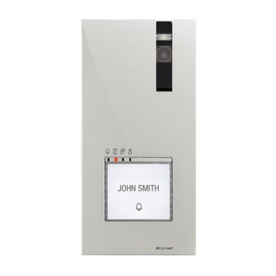
- Page 1 TECHNICAL MANUAL Quadra audio/video entrance panel Art. 4893M Passion.Technology.Design.
-
Page 2: Table Of Contents
Warning Intended use This Comelit product was designed for use in the creation of audio and video communication systems in residential, commercial or industrial settings and in public buildings or buildings used by the public. Installation All activities connected to the installation of Comelit products must be carried out by qualified technical personnel, with careful observation of the indications provided in the Manuals / Instruction sheets supplied with those products. -
Page 3: Description
Description Wall-mounted external unit for Quadra series door entry monitor. Die-cast aluminium front panel, wide-angle colour video camera and single LED for lighting at night. Mechanical buttons with the option of setting 1 to 4 call buttons via DIP-switch. Indicator LED for call sent, lock-release activated, audio activated and system busy. Loudspeaker volume adjustment and audio balancing. -
Page 4: Technical Features
Technical features MAIN FEATURES Type Monoblock entrance panel Type of finish Die-cast aluminium Audio/video system Wall-mounted Camera Colors Lens size (mm) Diagonal viewing angle (°) Minimum colour illumination (lux) Power supply Maximum current absorption (mA) Clamps LL RTE COM DO SE- SE+C NC NO Buttons to call Total buttons Microphone volume control... -
Page 5: Installation
Installation The camera must not be installed in front of light sources, or in places where the filmed subject is against the light. In dim environments, we recommend additional lighting is provided. OPEN Loudspeaker Microphone Settings You can download the free software (art. 1235A) to print the entrance panel name cards, using the adhesive pre-cut sheets available in our catalogue (art. -
Page 6: Changing Nameplates
• Before securing the screw, make sure that you do not need to program the external unit and make sure that the metal front panel does not rub against other metal parts, with consequent risk of damage to its insulating coating. •... -
Page 7: Settings
Settings Set the DIP-switches of S1 corresponding to the function that you want to programme as shown in the table below. DIP-SWITCH FUNCTION The lock-release relay and the second relay are controlled by 2 separate buttons (e.g. lock- release button and actuator button) DIP 1 The lock-release relay and the second relay are controlled by a single button (e.g. -
Page 8: Programming
Programming Call address programming for 2/4 users and additional external unit Take note of the DIP-switch settings. Enter programming mode. On the DIP-switch, set the code corresponding to the function you want to program as shown in the table. CODE DIP-SWITCH ON FUNCTION Button 1 enabled with call address 1 (default) -
Page 9: Operation With Additional External Units
Operation with additional external units • External unit with switching device art. 1404: default programming to be used with single external unit or with multiple external units connected with switching device art. 1404. • Secondary external unit: function to be used in systems with switching device art. 1405 and 2 external units. •... -
Page 10: Programming A Generic Call Address
Programming a generic call address Take note of the DIP-switch settings. Enter programming mode. Set the user code using the DIP-switches in accordance with the addressing table Reset the configuration of the DIP-switches. -
Page 11: Disabling The Com-Rte Contact
Disabling the COM-RTE contact Take note of the DIP-switch settings. Enter programming mode. Set the DIP-switches to position 206 (ON 2,3,4,7,8) in accordance with the addressing table Reset the configuration of the DIP-switches. To re-enable the function, repeat the procedure. -
Page 12: Connections
Connections Door open indication use variant 1209 4893M active input closed for DOOR OPEN signal Variant for using a safety door lock and additional power supply 12/24V AC/DC Local door-opener button 4893M Using the RC network for door lock filter on relay contacts On NO. - Page 13 C E R T I F I E D M A N A G E M E N T S Y S T E M S w w w . c o m e l i t g r o u p . c o m Via Don Arrigoni, 5 - 24020 Rovetta (BG) - Italy...