Jacuzzi J-485 Owner's Manual
Hide thumbs
Also See for J-485:
- Installation manual and use & maintenance (84 pages) ,
- Instructios for preinstallation (32 pages)
Table of Contents
Advertisement
Advertisement
Table of Contents

Related Manuals for Jacuzzi J-485


Summary of Contents for Jacuzzi J-485
- Page 1 J-495™ J-485™ J-475™ J-445 ™ J-435 ™ J-425 ™ OWNER’S MANUAL 6530-274G Rev B...
- Page 2 Attention New Spa Owner! Congratulations on the purchase of your new Jacuzzi® spa! The following is a list of automated functions performed by your spa. These functions are listed below in an attempt to suppress any operational concerns you may have during the first 24 hours of ownership! Also listed below are important maintenance recommendations you should observe on a regular basis to protect your new investment.
-
Page 3: Table Of Contents
J-495™ Spa Features..............20 J-495 Massage/Waterfall Selector Diagram ........ 21 J-495 Air Controls Diagram............22 J-485™ Spa Features..............23 J-485 Massage/Waterfall Selector Diagram ........ 24 J-485 Air Controls Diagram............25 J-475™ Spa Features..............26 J-475 Massage/Waterfall Selector Diagram ........ 27 J-475 Air Controls Diagram............ - Page 4 11.0 Operating Instructions............... 40 11.1 ProTouch™ Control Panel ............40 11.2 Activating the Jets Pumps ............40 11.3 Lights Menu ................. 41 11.4 Music Menu ................. 42 11.5 Connecting to the BLUEWAVE 2.0 Wireless Audio System ..44 11.6 Audio Settings Menu..............44 11.7 CLEARRAY on Demand ..............
- Page 5 14.0 Water Quality Maintenance ............68 14.1 pH Control..................68 14.2 Sanitizing ..................68 14.3 Other Additives ................69 14.4 CLEARRAY® (Ultraviolet) Water Purification System ....69 14.5 CLEARRAY® Bulb Replacement and Quartz Tube Maintenance ............... 70 15.0 Error/Display Messages ............73 16.0 Troubleshooting Procedures ............
-
Page 7: Important Spa Owner Information
Jacuzzi insulating cover in place at all times when the spa is not in use. Read and carefully follow the requirements for your spa’s support base found in the Section 4.0 titled, “Choosing a Location”... -
Page 8: Important Safety Instructions For All Spa Owners
J-400 Important Safety Instructions for all Spa Owners READ AND FOLLOW ALL INSTRUCTIONS CAREFULLY! This spa was manufactured to meet the standards and specifications outlined in the “Virginia Graeme Baker Pool and Spa Safety Act” (VGB Safety Act). When installing and using this spa, basic safety precautions should always be followed, including: DANGER: RISK OF SEVERE INJURY OR DROWNING! - Page 9 J-400 • A grounding wire connector is provided on this unit to connect a minimum No. 8 AWG (8.4 mm²) solid copper conductor between this unit and any metal equipment, metal enclosures of electrical equipment, metal water pipe, or conduit within 5 feet (1.5m) of the unit.
- Page 10 J-400 WARNING: RISK OF SEVERE INJURY OR DEATH! • Since excessive water temperatures have a high potential for causing fetal damage during the early months of pregnancy, if pregnant or possibly pregnant, consult your physician before using a spa. • Pregnant or possibly pregnant women should limit spa water temperatures to 100°F (38°C).
- Page 11 J-400 WARNING: In addition to maintenance of filters and water chemistry, proper ventilation is recommended to reduce the risk of contracting a waterborne illness (e.g. an infection, bacteria or virus) and/or respiratory ailments that could be present in the air or water. Consult a licensed architect or building contractor to determine your specific needs if installing your hot tub indoors.
- Page 12 J-400 FOR CALIFORNIA RESIDENTS ONLY NUR FÜR EINWOHNER KALIFORNIENS POUR LES RÉSIDENTS DE LA CALIFORNIE SEULEMENT PARA RESIDENTES DE CALIFORNIA ÚNICAMENTE WARNING: Drilling, sawing, sanding or machining wood products can expose you to wood dust, a substance known to the State of California to cause cancer.
-
Page 13: Entrapment Risk
J-400 Entrapment Risk The Consumer Products Safety Commission/USA has reported that users of pools and spas have become entrapped (stuck) to drain and/or suction fittings causing death, drowning, or serious injury (see diagram below). This spa was manufactured to meet the standards and specifica- tions outlined in the “Virginia Graeme Baker Pool and Spa Safety Act”... -
Page 14: Hyperthermia
A Warning Sign is provided in your warranty packet. Please install at a location near your spa, where it is visible to users of the spa. For additional or replacement Warning Signs please contact your local Jacuzzi dealer and reference item number #6530-082. -
Page 15: Important Safety Instructions
Visit www.Jacuzzi.com for weight information. If the spa is placed on a surface, which does not meet these requirements, damage to the skirt and/or the spa shell may result. -
Page 16: Outdoor Location
J-400 WARNING: Proper drainage is required. The installation must not allow the spa equipment bay to become flooded or wetted (by external water). It is your responsibility, and the responsibility of any installation contractor you hire, to make sure that all applicable codes and/or local construction requirements are met. -
Page 17: Indoor Location
J-400 • Consider locating your spa away from any reflective surface or glass to prevent any damage to the synthetic skirt. • Do not shim the spa. To ensure proper support the spa must sit flat on the intended foundation. Indoor Location For indoor installations many factors need to be considered before installing a spa indoors. -
Page 18: General Electrical Safety Instructions
Nonetheless, this spa must be installed properly to ensure dependable usage. Please contact your local Jacuzzi dealer or local building department should you have any questions regarding your installation. Proper grounding is extremely important. Jacuzzi spas are equipped with a current collector system. - Page 19 Tilt the panel and pull down to remove. Place the panel in a safe location to prevent from damaging it. • The Jacuzzi indicator light is installed on the front panel. Take care when removing the panel to avoid damaging the wires or light.
- Page 20 J-400 Figure B Equipment Area Note: Equipment location and quantity (such as pumps, CLEARRAY system, stereo, drain, heater etc.) varies by model. 1. ProTouch™ Control Panel 10. Pump Drain Plugs(s) 2. ProTouch™ Control Box 11. Power Supply Entrance(s) 3. Heater 12.
-
Page 21: Power Requirements
1/4AT 250VAC Green F7 30A Power Requirements Jacuzzi ® spas are designed to provide optimum performance and flexibility of use when connected to their maximum electrical service. They are configured at the factory. The most common electrical connections are listed below:... -
Page 22: Spa Fill Up Procedure
Clear all debris from the spa. Although the spa shell has been polished at the factory, you may want to treat it with a specially formulated spa cleaner. Consult your authorized Jacuzzi dealer for additional information prior to filling spa. - Page 23 J-400 WARNING: RISK OF POISONING OR DEATH. Never leave chemicals opened and accessible to anyone. Use chemicals according to the vendor’s instructions. Always store chemicals in a safe and/or locked location. Keep away from and out of reach of children. 6.
- Page 24 Model Fill Volume* Dichlor J-495........560 Gal (2,120 L) ........ 14.0 oz J-485........435 Gal (1,647 L) ........ 11.0 oz J-475........440 Gal (1,666 L) ........ 11.0 oz J-445........380 Gal (1,438 L) ......... 9.5 oz J-435........360 Gal (1,363 L) ......... 9.0 oz J-425........340 Gal (1,287 L) ......... 9.0 oz *Use average fill volume for chemical maintenance 10.
- Page 25 Water that is too soft can be corrosive to metal components. 13. Consult your authorized Jacuzzi dealer for chemical recommendations, then add chemicals to hot tub water to achieve a constant sanitizer reading within the levels recommended on the inside cover of this manual.
-
Page 26: Spa Features
J-400 Spa Features J-495™ Spa Features 19 19 19 19 6:45p 1. ProTouch™ Control Panel 13. FX Rotational Jets (4) 2. Air Control Valves (5) 14. MX2 Jets (3) 15. PX Jets (4) 3. Massage Selectors 16. FX Large Rotational Jets (3) with lights (2) 17. -
Page 27: J-495 Massage/Waterfall Selector Diagram
J-400 J-495 Massage/Waterfall Selector Diagram 6:45p Massage Selectors (1-2) • Massage selector 1 diverts jets pump Nº 1 output between jets groups 1a-1b. • Massage selector 2 diverts jets pump Nº 2 output between jets groups 2a-2b. Jets Without Massage Selector Controls •... -
Page 28: J-495 Air Controls Diagram
J-400 J-495 Air Controls Diagram 6:45p Air Controls Operation • Toggle air controls 1-5 to add air to designated jet groups. Spa operation subject to change without notice... -
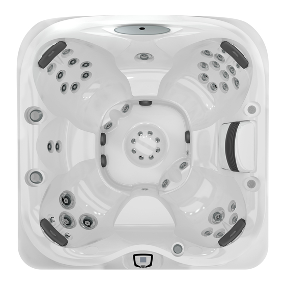
Page 29: J-485™ Spa Features
J-400 J-485™ Spa Features 6:45p 14. RX Jets (8) 1. ProTouch™ Control Panel 2. Waterfall Control Valve 15. FX Small Jets (8) 3. Air Controls (4) 16. FX Large Jets (3) 4. Adjustable Pillows (4) 17. PX Jets (2) 5. Waterfall 18. -
Page 30: J-485 Massage/Waterfall Selector Diagram
J-400 J-485 Massage/Waterfall Selector Diagram 6:45p Massage Selectors (1-2) • Massage selector 1 diverts jets pump Nº 1 output between jets groups 1a-1b. • Massage selector 2 diverts jets pump Nº 2 output between jets groups 2a-2b. Continuously Powered Jets •... -
Page 31: J-485 Air Controls Diagram
J-400 J-485 Air Controls Diagram 6:45p Air Controls Operation • Toggle air controls 1-4 to add air to designated jet groups. Spa operation subject to change without notice... -
Page 32: J-475™ Spa Features
J-400 J-475™ Spa Features 6:45p ProTouch™ Control Panel 14. RX Jets (6) Waterfall Control Valve 15. FX Small Jets (8) Air Controls (4) 16. FX Large Jets (5) Adjustable Pillows (4) 17. PX Jets (8) Waterfall 18. Optional BLUEWAVE® 2.0 Filter/Skimmer Grill Audio System Massage Selectors with lights (2) -
Page 33: J-475 Massage/Waterfall Selector Diagram
J-400 J-475 Massage/Waterfall Selector Diagram 6:45p Massage Selectors (1-2) • Massage selector 1 diverts jets pump Nº 1 output between jets groups 1a-1b. • Massage selector 2 diverts jets pump Nº 2 output between jets groups 2a-2b. Continuously Powered Jets •... -
Page 34: J-475 Air Controls Diagram
J-400 J-475 Air Controls Diagram 6:45p Air Controls Operation • Toggle air controls 1-4 to add air to designated jet groups. Spa operation subject to change without notice... -
Page 35: J-445™ Spa Features
J-400 9.10 J-445™ Spa Features 6:45p 1. ProTouch™ Control Panel 13. FX Rotational Jets (8) 2. Waterfall Control Valve 14. RX Jets (8) 3. Air Controls (4) 15. FX Small Jets (8) 4. Adjustable Pillows (4) 16. Optional BLUEWAVE® 2.0 5. -
Page 36: J-445 Massage/Waterfall Selector Diagram
J-400 9.11 J-445 Massage/Waterfall Selector Diagram 6:45p Massage Selectors (1-2) • Massage selector 1 diverts jets pump Nº 2 output between jets groups 1a-1b. • Massage selector 2 diverts jets pump Nº 1 output between jets groups 2a-2b. Continuously Powered Jets •... -
Page 37: J-445 Air Controls Diagram
J-400 9.12 J-445 Air Controls Diagram 6:45p Air Controls Operation • Toggle air controls 1-4 to add air to designated jet groups. Spa operation subject to change without notice... -
Page 38: J-435™ Spa Features
J-400 9.13 J-435™ Spa Features 6:45p 1. ProTouch™ Control Panel 13. FX Rotational Jets (6) 2. Waterfall Control Valve 14. RX Jets (8) 15. FX Small Jets (10) 3. Air Controls (3) 16. PX Spinner Jets (2) 4. Adjustable Pillows (3) 17. -
Page 39: J-435 Massage/Waterfall Selector Diagram
J-400 9.14 J-435 Massage/Waterfall Selector Diagram 6:45p Massage Selectors (1-2) • Massage selector 1 diverts jets pump Nº 2 output between jets groups 1a-1b. • Massage selector 2 diverts jets pump Nº 1 output between jets groups 2a-2b. Continuously Powered Jets •... -
Page 40: J-435 Air Controls Diagram
J-400 9.15 J-435 Air Controls Diagram 6:45p Air Controls Operation • Toggle air controls 1-3 to add air to designated jet groups. Spa operation subject to change without notice... -
Page 41: J-425™ Spa Features
J-400 9.16 J-425™ Spa Features 6:45p 1. ProTouch™ Control Panel 14. MX2 Jets (3) 2. Air Control Valves (4) 15. PX Jets (4) 3. Massage Selector with light 16. FX2 Large Rotational Jets (2) 4. Lighted Cup Holders (3) 17. Optional BLUEWAVE® Audio 5. -
Page 42: J-425 Massage/Waterfall Selector Diagram
J-400 9.17 J-425 Massage/Waterfall Selector Diagram 6:45p Massage Selector • Massage selector 1 diverts jets pump Nº 1 output between jet groups 1a-1b. Jets Without Massage Selector Controls • Jets (2) are always on when jets pump Nº 1 is running. •... -
Page 43: J-425 Air Controls Diagram
J-400 9.18 J-425 Air Controls Diagram 6:45p Air Controls Operation • Toggle air controls 1-4 to add air to designated jet groups. Spa operation subject to change without notice... -
Page 44: Registration And Start-Up
Follow these steps to register your spa. 1. Using your home computer or other device, connect to the internet. 2. Go to www.Jacuzzi.com website to register your spa. 3. Click Outdoor Hot Tubs 4. Click For Owners 5. Click Warranty and Manuals 6. -
Page 45: Protouch™ Control Panel
The J400 ProTouch system makes operating your spa a breeze. You can navigate through the menus and sub-menus with ease. Simply touch the icons on the LCD display to begin operating your new Jacuzzi spa. A. Home Menu Control Buttons The Home Menu, Figure 10.3a, provides access to spa functions and... -
Page 46: Operating Instructions
The time must be manually adjusted. 11.0 Operating Instructions 11.1 ProTouch™ Control Panel Your Jacuzzi spa is equipped with a ProTouch control panel; massage selectors, and air control knobs. These controls let you operate many of the special functions of your Jacuzzi spa. 11.2 Activating the Jets Pumps From the Home Menu, (Figure 11.2a), tap... -
Page 47: Lights Menu
J-400 = Jets Pump 1 Button = Jets Pump 2 Button = Jets Pump 3 Button (if applicable) = Back Button: Tap to go back to the previous menu. = Invert Button: Tap to invert the display image. JETS ICON 1. -
Page 48: Music Menu
J-400 = Intensity Indicator: Displays the current intensity level of the lights by the number of bars filled in. This will only work with the solid color option. If the blending mode is on, the light bulb is grayed out. The range is from 0 to 5. = Speed Control Button (Increase): Tap to increase the blending speed, of the colors, to the maximum speed of 5. - Page 49 J-400 MUSIC 6:45p Track Name Vol: 30 Figure 11.4b Figure 11.4a = Power Button: Tap to turn the stereo on and off. = Bluetooth Settings: Tap to use your Bluetooth device with the stereo. This is the default setting. = Auxiliary Settings: Tap to use your Auxiliary device with the stereo.
-
Page 50: Connecting To The Bluewave 2.0 Wireless Audio System
J-400 11.5 Connecting to the BLUEWAVE 2.0 Wireless Audio System A. Connecting with your Bluetooth® device To bridge a connection between the BLUEWAVE 2.0 Wireless Audio System and your Bluetooth® device, follow the steps below. Note: The BT icon cannot be selected manually unless a Bluetooth connection is established with your device. -
Page 51: Clearray On Demand
J-400 Treble = Treble Adjustment: Slide from side to side to adjust the Treble range from -5 to 5. This feature can be used to create a custom sound. = Rock Preset: Tap to activate the “Rock” music audio rock setting. -
Page 52: Waterfall Control
Note: Certain jets may draw air even though they are closed. This is considered normal. 11.13 Selecting the Desired Massage Action Your Jacuzzi spa is equipped to allow you to customize the massage action you desire. Each model incorporates a massage selector that allow you to customize the massage and performance by diverting water between various jet systems. -
Page 53: Optional Smarttub™ System
J-400 11.16 Optional SmartTub™ System Advances in technology have allowed us to create a better and smarter hot tub. Our SmartTub™ system operates on a cellular network. The advantages of this system are: • A more stable connection to internet for outdoor environment. The SmartTub™... -
Page 54: Programming And Operation Instructions
12.0 Programming and Operation Instructions Your Jacuzzi spa is equipped with setting menus that allow you to pro- gram and activate different components of the spa. With our ProTouch control panel, programming your spa has never been easier. In the sec- tions that follow, we will guide you through the process of programming the spa to fit your personal comfort. -
Page 55: Programming The Heating Mode
= Scroll Buttons: Scroll up and down to view the selections available. 12.1 Programming the Heating Mode Heat & Filter Your Jacuzzi spa is equipped with 3 modes of heating, Figure 12.1a. An automatic mode called Auto “Auto,” where the spa’s temperature is maintained Econo at all times. -
Page 56: Programming The Primary Filter
J-400 12.2 Programming the Primary Filter To access the “Primary Filter” feature, tap from the Heat & Filter menu, Figure 12.2a, to enter the “Primary Filter” programming menu, Figure 12.2b. Heat & Filter Primary Filter Auto Start 12pm Econo Filter Figure 12.2b Figure 12.2a During a primary filtration, the circulation pump, CLEARRAY and ozone... -
Page 57: Programming The Secondary Filter
J-400 Summer Logic: In warm weather, the water temperature in the spa may exceed the set temperature. This condition may occur due to heat transference from the filter/circulation pump and jets pumps. If the water temperature is higher than 95°F (35°C) and rises 2°F (1°C) above the set temperature, a “Summer Logic”... -
Page 58: Cleanup Cycle
J-400 12.4 Cleanup Cycle The cleanup cycle occurs once per day at 12:00 pm (noon) for 2 minutes. This is not user programmable. The Jets Pump 1 and the Circulation Pump will turn on for one minute and then shut off. Then Jets Pump 2 will turn on and run for 1 minute then shut off. - Page 59 J-400 1. From the “Water Care” Menu you can to set the CLEARRAY UV bulb timer, Figure 12.6c. 2. Tap to change the days in 10-day increments. The range is from OFF to 365 days. The CLEARRAY UV timer counts down by days not usage.
- Page 60 J-400 C. Programming the ProClarity/ProClear Filter Timer A programmable filter timer can be set to remind ProClarity you when to clean or replace the filters and 60 days left skimmer bag. Tap (Figure 12.6b) ProClarity to enter the Programming Menu. 1.
-
Page 61: Optional Wi-Fi Setup (Not Applicable If The Optional Smarttub™ System Is Installed)
J-400 12.7 Optional Wi-Fi Setup (not applicable if the optional SmartTub™ system is installed) From the Settings Menu, tap to highlight the “Wi-Fi” Menu tab in Orange. Tap to enter the programming options, Figures 12.7a Wi-Fi and 12.7b. Make sure you have downloaded the Wi-Fi App for this setup. SETTINGS Wi-Fi Connect Water Care... -
Page 62: Locking The Spa
J-400 12.8 Locking the Spa From the Settings Menu, tap to highlight the “Lock” menu tab in Orange. Tap (Figure 12.8a) to enter the programming Lock options, Figures 12.8a and 12.8b. You can prevent users from changing certain features of the spa. When a lock feature is active, the lock icon will appear on the Main Menu. -
Page 63: Programming The Time And Date
J-400 D. To Unlock (Figure 12.8c): Lock 1. Enter the Lock menu. The type of lock that is active will already be highlighted in Orange. 2. Tap (the first block) to start entering the code. Then move on to the next number until Unlock the four-digit unlock code has been entered. -
Page 64: Programming The Language
J-400 6. Tap the year block to program. 1 30 2015 7. Tap to make changes. 8. Tap to save and accept the changes. 9. Tap to return to the “Settings” Menu. 12.10 Programming the Language From the Settings Menu, tap to highlight the “Language”... -
Page 65: Spa Maintenance
J-400 13.0 Spa Maintenance Proper and regular maintenance of your spa will help it retain its beauty and performance. Your authorized Jacuzzi dealer can supply you with all the information, supplies, and accessory products you will need to accomplish this. - Page 66 J-400 A. Cleaning the filters and filter bag To ensure optimum performance: 1. The ProClarity™ filter cartridge (A) must be cleaned every month and replaced every 18 months. 2. The ProClarity Depth filter (B) must be replaced every 3 months. 3.
- Page 67 J-400 Cartridge 1 Remove the filter pin If used, remove the Lift unthreaded filter in order to separate chemical feeder as cartridge from skimmer the ProClarity filter and instructed prior to rinsing well. the filter cartridge. Rinse canister. debris from filter pleats Note: Primary filter using a garden hose and fitting is the one with...
-
Page 68: Draining And Refilling
During this time, it is also recommended that you use Jacuzzi’s Jet Line Cleaner to clean the internal plumbing lines from buildup and debris. - Page 69 Place the panel in a safe location to prevent from damag- ing it. • The Jacuzzi indicator light is installed on the front panel. Take care when removing the panel to avoid damaging the wires or light. Remove the wing nuts from the indicator light to remove the light housing, Figure 13.2c.
- Page 70 J-400 3. Locate one of the two drains that you would 6:45p like to use, Figure 13.2d. Either the Quick Drain (A) or the 3/4" drain valve (B). Once you choose a draining method, follow the procedures for that method. Figure 13.2d 4.
-
Page 71: Cleaning The Spa Interior
13.7 Cover Care and Maintenance Certain hot tub covers distributed by Jacuzzi® Hot Tubs have a vinyl or PROLAST™/PROLAST™ Extreme encasement. This vinyl or PROLAST/ PROLAST Extreme encasement also referred to as the cover “skin” is attractive and durable. -
Page 72: Winterizing
13.8 Winterizing Your Jacuzzi spa is designed to automatically protect itself against freezing when operating properly. During periods of severe freezing temperatures, you should check periodically to be certain that the electrical supply to the spa has not been interrupted. In extreme, bitter cold weather (less than 32°F) we recommend that the circulation pump is... -
Page 73: Restarting Your Spa In Cold Weather
11. Re-install cabinet panels and cover spa so that no casual moisture can enter into it. Consult your Jacuzzi dealer if you have any questions regarding winter use or winterizing. 13.9 Restarting Your Spa in Cold Weather... -
Page 74: Water Quality Maintenance
That is why almost all spa water test kits contain a measure for pH as well as sanitizer. Jacuzzi offers products that help you maintain the ideal range. These chemicals are for use in the U.S. -
Page 75: Other Additives
With our chemical products your authorized Jacuzzi dealer can advise you on the use of these additives. Jacuzzi chemicals are for use in the U.S. only. 14.4 CLEARRAY® (Ultraviolet) Water Purification System... -
Page 76: Clearray® Bulb Replacement And Quartz Tube Maintenance
J-400 WARNINGS: • Do not operate the UV-C emitter when it is removed from the appli- ance enclosure. • This appliance contains a UV-C emitter. • Unintended use of the appliance or damage to the housing may result in the escape of dangerous UV-C radiation. UV-C radiation may, even in little doses, cause harm to the eyes and skin. - Page 77 J-400 2. Once the UV bulb has cooled off remove the CLEARRAY System enclosure cover (9) and gasket (8) by removing the four screws (10). This will expose the UV bulb and connections, Figure 2. DANGER: NEVER REMOVE COVER FIGURE 2 WITHOUT FIRST TURNING OFF AT POWER SOURCE AND DRAINING THE SPA.
- Page 78 J-400 11. Reinstall and hand tighten the quartz seal compression nut (5) by turning it clockwise. 12. Refill your spa. 13. System Test 1: Assure there is no water dripping from the seal compression nut (5). If water is visible, STOP and tighten the compression nut (5) using a pair of channel lock pliers to a maximum of 1/4 turn.
-
Page 79: Error/Display Messages
15.0 Error/Display Messages There are a number of unique functions designed into your Jacuzzi spa to protect it from damage and/or to aid in troubleshooting. When this occurs the spa will notify you by showing the screen below, Figure 15.0a. A solid white light indicates that all operations are normal. - Page 80 J-400 8. Closed Flow Switch on Start-up: Flow switch is non-functional. Closed or shorted flow switch on system start-up (system disabled). Contact your authorized dealer or service organization. 9. Frozen on Start-up: Flow switch is non-functional. Shorted flow switch on system start-up (system disabled) and freeze condition detected.
- Page 81 J-400 14. Watchdog Protection: DO NOT ENTER SPA! Spa water temperature is above acceptable limits. Your spa is deactivated. Remove spa cover to speed cooling. Contact your authorized dealer or service organization. Note: The heater icon will be blinking and the error icon will be displayed under the temperature.
- Page 82 J-400 22. ProClarity/ProClear Filter Reminder: This message Reminder will appear when the filter reminder time has expired It’s time to clean or replace your ProClarity and Pro- (Figure 15.0d). Remove the ProClarity/Proclear filters Clear filters. Contact your authorized dealer if new and filter/debris bag for cleaning or replacement.
-
Page 83: Troubleshooting Procedures
16.0 Troubleshooting Procedures In the unlikely event your spa is not working the way you believe it should, please first review all the installation and operating instructions in this manual and check the message on the panel display; second, if you are still not satisfied it is working properly, please follow the appropriate troubleshooting instructions. - Page 84 Your input as a Jacuzzi spa owner is a cherished part of this process. If you have any comments or suggestions, or if you wish to be informed on any new products for your spa, please write to us.
-
Page 85: Typical Spa Wiring Diagrams
J-400 17.0 Typical Spa Wiring Diagrams 17.1 Wiring diagram for North American 60 Hz Models Only 2-Pole Circuit Breaker with 2-Wire Grounded Load Connection (3 Wires to Hot Tub, 2-Hot (L1-L2), 1-Ground) 240 VAC Ground/Bonding Lug White (N) Black (L1) 2-Pole GFCI Red (L2) -
Page 86: Circuit Board Wiring Diagrams
J-400 18.0 Circuit Board Wiring Diagrams 18.1 2-Pump Domestic 60Hz Wiring Diagram BLUEWAVE STEREO SmartTub (OPTIONAL) FLOW (Optional) SENSOR WATER CONTROL PANEL SENSOR ZONE1 ZONE2 ZONE 1 ZONE 2 LIGHT HARNESS SERIAL ADCM WATER ZONE 2 ZONE 1 HI-LIMIT TEMP Exterior Lights COLOR or Step Light... -
Page 87: 3-Pump Domestic 60Hz Wiring Diagram
J-400 18.2 3-Pump Domestic 60Hz Wiring Diagram SERIAL ADCM WATER TEMP HI-LIMIT TEMP 1/4AT 250VAC FUSE PUMP 3... -
Page 88: Dip Switch Settings
J-400 18.3 Dip Switch Settings The dip switches are at the S1 location on the board. A. Switch settings for Domestic 60Hz Models DOMESTIC DIP SWITCH SETTINGS S1 LOCATION (factory default) DIP SWITCH NUMBER BREAKER OFF OFF OFF OFF OFF OFF OFF OFF OFF OFF 50A* OFF OFF ON OFF OFF OFF OFF OFF OFF OFF...