Advertisement
Quick Links
Brief Operating Instructions
Stamosens CXM750/CXS70
#
Warning!
These Brief Operating Instructions do not substitute the Operating Instructions!
In particular pay attention to the safety instructions in chapter 1 and to the special notes in the other chapters of the Operating Instructions!
Installation and Wiring
Installation
• Select a measuring point where representative measurement can be taken.
Do not mount the sensor where medium flow is turbulent and fast-flowing.
• We recommend to fit the transmitter with a weather protection cover (see
"Accessories").
• Attach the sensor to a special extension tube. Due to the weight of the sensor
(approx. 5 kg), the sensor cable does not provide sufficient support. Never carry the
sensor by its cable.
• The best fixture is a pendulum frame which holds the sensor vibration-free.
• Install the system at an easily accessible position to prevent danger for the operating
personnel (during commissioning or when carrying out maintenance and cleaning
work).
• Route all cable connections to prevent mechanical damage and interference from
other lines.
• Install measuring channels of the sensor in the direction of flow to obtain a self-
cleaning effect.
• The activated sludge version of the sensor is equipped with a cleaning unit which
prevents soiling or blocking due to particles by compressed air. For other applications
with soiling contents, the cleaning unit is available as an accessory.
Install the air outflow of the cleaning unit at the narrow side of the light slit.
241 / 9.49
212 / 8.35
198 / 7.80
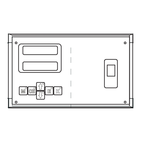
Abb. 1:
Transmitter dimensions
mm / inch
Abb. 2:
Sensor dimensions
KA215C/07/en/07.04
115 / 4.53
60 / 2.36
69 / 2.72
198 / 7.80
mm / inch
a0000949-en
360 / 14.17
a0000950-en
Electrical connection
Terminal assignment
51509157
Output /
Duo-
Ausgang
23
TxD
Version:
Sensor 2
27
0V
Sensor 1
22
RxD
+24V
-
26
-
33
30
21
CTS
+
32
+
29
+24V
25
20
GND
Shield/
Shield/
31
28
24
19
0V
Schirm
Schirm
I 1
I 2
Input /
RS232
0/4-20 mA
Eingang
Fig. 3:
Electrical connection transmitter with power supply 80 ... 250 V AC
51509391
Output /
Duo-
Ausgang
23
TxD
Version:
Sensor 2
27
0V
Sensor 1
22
RxD
+24V
-
26
-
33
30
21
CTS
+
+24V
32
+
29
25
20
GND
Shield/
Shield/
31
28
24
0V
19
Schirm
Schirm
I 1
I 2
Input /
RS232
0/4-20 mA
Eingang
Fig. 4:
Electrical connection transmitter with power supply 24 V AC/DC
Cleaning unit
Fuse
PE
L1
1
T
1A
230V AC / 50Hz
or
115V AC / 60Hz
Fig. 5:
Connection of the cleaning unit
Terminals voltage to ground even when the unit is switched off !!!
Klemmen führen auch bei ausgeschaltetem Gerät Spannung !!!
Relais: Load/Last max. 250V~/2A, 30V=/1A
NO
18
15
12
9
6
NC
17
14
11
8
5
COM
16
13
10
7
4
Cleaning/
Error/
Alarm 1/
Alarm 2/
Hold
GW 2
Reinigung
Störung
GW 1
Supply voltage only 24V DC/AC !!!
Versorgungsspannung nur 24V DC/AC !!!
Relais: Load/Last max. 250V~/2A, 30V=/1A
NO
18
15
12
9
6
NC
17
14
11
8
5
COM
16
13
10
7
4
Cleaning/
Error/
Alarm 1/
Alarm 2/
Hold
Reinigung
Störung
GW 1
GW 2
N
PE
Transmitter
2
N
1
L
18
16
3
Supply / Netz:
80-250 V~
3
F1
2
N
1
L
T 500 mA
a0000952
3
F1
-
2
L
+
1
L
T 2 A
a0000953
a0000951-en
Advertisement

Related Manuals for Endress+Hauser Stamosens CXM750


Summary of Contents for Endress+Hauser Stamosens CXM750
- Page 1 Brief Operating Instructions Stamosens CXM750/CXS70 Warning! These Brief Operating Instructions do not substitute the Operating Instructions! In particular pay attention to the safety instructions in chapter 1 and to the special notes in the other chapters of the Operating Instructions!
- Page 2 Commissioning One-point calibration Action Display Operating keys and their function Leave the sensor to rest in the medium for approx. 1 hour. Take a sample in the direct vicinity of the sensor and determine the nitrate content in the The operating keys and the integrated indicator LEDs have the following functions: laboratory.