Table of Contents
Advertisement
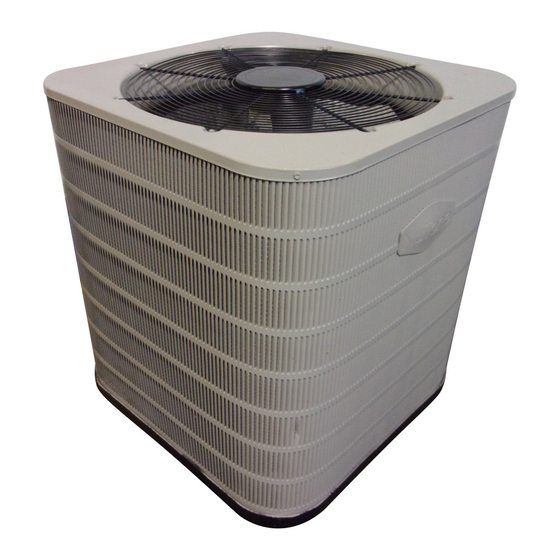
Split SyStem air conditioner
inStallation inStrUctionS
*S4Be / *Sa4Be - 018, 024, 030, 036, 042, 048, & 060 (1.5, 2, 2.5, 3, 3.5, 4, & 5 ton) SerieS
important
attention inStallerS:
it is your responsibility to know this product
better than your customer. this includes
being able to install the product according
to strict safety guidelines and instructing the
customer on how to operate and maintain the
equipment for the life of the product. Safety
should always be the deciding factor when
installing this product and using common
sense plays an important role as well. pay
attention to all safety warnings and any other
special notes highlighted in the manual.
improper installation of the unit or failure to
follow safety warnings could result in serious
injury, death, or property damage.
these instructions are primarily intended to
assist qualified individuals experienced in the
proper installation of this appliance. Some
local codes require licensed installation/
service personnel for this type of equipment.
please read all instructions carefully before
starting the installation. return these
instructions to the customer's package for
future reference.
do not deStroy. pleaSe read careFUlly &
Keep in a SaFe place For FUtUre reFerence.
14 Seer, Single phaSe modelS
important SaFety inFormation .................. 2
air conditioner inStallation ..................... 3
General Information ............................................... 3
Before You Install this Unit ..................................... 3
Locating the Air Conditioner ................................... 3
Packaging Removal ............................................... 3
Ground Level ......................................................... 3
Roof Mount ............................................................ 3
Indoor & Outdoor Unit ............................................ 3
electrical Wiring ........................................... 4
Pre-Electrical Checklist .......................................... 4
Line Voltage ........................................................... 4
Grounding .............................................................. 5
Diagnostics Module .......................... 5
Compressor Protection ........................................ 5
Resetting Alert Codes .......................................... 5
Thermostat Connections ........................................ 5
Start Up & adJUStmentS ............................... 5
Pre-Start Check List ............................................... 5
Start-Up Procedures .............................................. 6
Air Circulation - Indoor Blower ............................. 6
System Cooling .................................................... 6
System Heating (optional) ................................... 6
reFrigerant charging .................................. 6
Charging the Unit in AC mode ............................... 6
Application Notes & Charging Info ......................... 7
Table 3. Charging Table for 1.5 Ton Models ....... 7
Table 4. Charging Table for 2 Ton Models .......... 8
Table 5. Charging Table for 2.5 Ton Models ....... 8
Table 6. Charging Table for 3 Ton Models .......... 9
Table 7. Charging Table for 3.5 Ton Models ....... 9
Table 8. Charging Table for 4 Ton Models .......... 10
Table 9. Charging Table for 5 Ton Models .......... 10
Figure 3. Charging Chart for 2 - 5 Ton Units ....... 11
air conditioner maintenance ..................... 11
electrical inFormation ............................... 12
Table 10. LED Diagnostics for CoreSense
Diagnostics Module ............................................. 12
Figure 4. Wiring Diagram for 1.5 - 4 Ton Models
TM
without CoreSense
Figure 5. Wiring Diagram for 1.5 - 4 Ton Models
TM
(with CoreSense
) ............................................. 13
Figure 6. Wiring Diagram for 5 Ton Models
TM
(without CoreSense
Figure 7. Wiring Diagram for 5 Ton Models
TM
(with CoreSense
) ............................................. 15
inStallation checKliSt ................................. 16
replacement partS ........................................ 16
TM
) .......................................... 12
) ........................................ 14
Advertisement
Table of Contents

Related Manuals for Nordyne S4BE-060KA Series


Summary of Contents for Nordyne S4BE-060KA Series
-
Page 1: Table Of Contents
Split SyStem air conditioner 14 Seer, Single phaSe modelS inStallation inStrUctionS *S4Be / *Sa4Be - 018, 024, 030, 036, 042, 048, & 060 (1.5, 2, 2.5, 3, 3.5, 4, & 5 ton) SerieS important important SaFety inFormation ....2 air conditioner inStallation ..... 3 attention inStallerS: General Information .......... -
Page 2: Important Safety Information
important SaFety inFormation Warning: INSTALLER: Please read all instructions before servicing this equipment. Pay attention to all safety warnings and any the information listed in this manual must be other special notes highlighted in the manual. Safety markings are used frequently throughout this manual to designate a followed during the installation, service, and degree or level of seriousness and should not be ignored. -
Page 3: Air Conditioner Installation
air conditioner inStallation √ All units are securely packed at the time of shipment and upon arrival should be carefully inspected for damage prior general information to installing the equipment at the job site. Verify coil fins The S4BE series air conditioner is designed only for outdoor are straight. -
Page 4: Electrical Wiring
• When connecting refrigerant linesets together, it is Figure 6, (page 14) Figure 7, (page 15) , & recommended that dry nitrogen be flowing through the Inspect for loose connections. joints during brazing to prevent internal oxidation and line Voltage scaling. -
Page 5: Grounding
grounding Compressor Common Wire Warning: the unit cabinet must have an uninterrupted or Reset Button unbroken electrical ground to minimize personal injury if an electrical fault should occur. do not Run / Alert use gas piping as an electrical ground! (Yellow LED) This unit must be electrically grounded in accordance with local codes or, in the absence of local codes, with the National... -
Page 6: Start-Up Procedures
Start-Up procedures • Cooling mode charging charts and tables are applicable only to matched assemblies of this equipment and listed The thermostat's function mode should be set to OFF and airflows for the indoor coil. Refer to the Quick Reference the fan mode should be set to AUTO. -
Page 7: Application Notes & Charging Info
application notes & charging info note: Before using Figure 3, (page 11) , make sure the unit is in a stable operating mode. As shown in the (cooling mode only) chart, the ideal system sub-cooling can vary over the range •... -
Page 8: Table 4. Charging Table For 2 Ton Models
Shaded boxes indicate flooded conditions. Rated design values. The suction pressure will vary from design value if indoor air flow, entering dry bulb, or entering wet bulb temperatures are lower than design. 1. All pressures are listed in psig and all temperatures in ° F 2. -
Page 9: Table 6. Charging Table For 3 Ton Models
Shaded boxes indicate flooded conditions. Rated design values. The suction pressure will vary from design value if indoor air flow, entering dry bulb, or entering wet bulb temperatures are lower than design. 1. All pressures are listed in psig and all temperatures in ° F 2. -
Page 10: Table 8. Charging Table For 4 Ton Models
8. charging table for 4 ton models S4Be-060Ka SerieS oUtdoor temperatUre (°F) SUct. preSS. liq. diS. liq. diS. liq. diS. liq. diS. liq. diS. liq. -
Page 11: Air Conditioner Maintenance
S4BE / SA4BE Charging Chart 2, 2.5, 3.5, 4 TON MODELS 1.5, 3, 5 TON MODELS R-410A SATURATION Remove refrigerant if above the curve. Add refrigerant if below the curve. Do not add or remove refrigerant if pressure reading is between unit curves and saturation curve. -
Page 12: Electrical Information
electrical inFormation alert code alert condition locK leVel locK indication normal run Normal operation, no trip Solid Yellow code 1 Long run time. Compressor is on running for more than 18 hours. Yellow Flash 1 (Code1 is disabled in Heat Pump Mode) code 2 Compressor (pressure) trip. - Page 13 Figure 5. Wiring diagram for 1.5 - 4 ton models (with coreSense...
- Page 14 Figure 6. Wiring diagram for 5 ton models (without coreSense...
- Page 15 Figure 7. Wiring diagram for 5 ton models (with coreSense...
-
Page 16: Installation Checklist
inStallation checKliSt electrical SyStem inStallation addreSS: Electrical connections tight? Line voltage polarity correct? CITY ________________________ STATE ________________ UNIT MODEL # ________________________________________ Rated Voltage: ___________________________________ VOLTS UNIT SERIAL # _______________________________________ L1-L2 Volts: _____________________________________ VOLTS inStaller name: L1-L3 Volts: _____________________________________ VOLTS CITY _______________________ STATE ________________ L2-L3 Volts: _____________________________________ VOLTS Unit Installed Minimum clearances...