
Related Manuals for Panasonic BM-ED500


Summary of Contents for Panasonic BM-ED500
-
Page 1: Control Unit
Control Unit Operating Instructions BM-ED500 Model No. Before attempting to connect or operate this product, please read these instructions carefully and save this manual for future use. - Page 2 You should note the serial number of this unit in the space provided and retain this book as a permanent record of your purchase to aid identification in the event of theft. Model No. BM-ED500 Serial No. For U.S.A...
-
Page 3: Important Safety Instructions
IMPORTANT SAFETY INSTRUCTIONS 1) Read these instructions. 2) Keep these instructions. 3) Heed all warnings. 4) Follow all instructions. 5) Do not use this apparatus near water. 6) Clean only with dry cloth. 7) Do not block any ventilation openings. Install in accordance with the manufacturer's instructions. 8) Do not use near any heat sources such as radiators, heat registers, stoves, or other apparatus (including amplifiers) that produce heat. -
Page 4: Table Of Contents
IMPORTANT SAFETY INSTRUCTIONS ... 3 PREFACE ... 5 FEATURES ... 6 NOTIFICATION ABOUT THIS DOCUMENT ... 7 TRADEMARKS ... 7 LIMITATION OF LIABILITY ... 7 DOCUMENT CONVENTION ... 8 PRECAUTIONS ... 9 MAJOR OPERATING CONTROLS AND THEIR FUNCTIONS ... 10 I External View ... -
Page 5: Preface
PREFACE Control Unit BM-ED500 is used in an access control system. The control unit, which carries out the enrollment and recognition of iris data, which is generated from the iris images captured by Iris Camera BM-ET500, is available for following uses. -
Page 6: Features
Iris cameras, control units, and the administration PC can compose an access control system in combination with access control panels* and electric locks* These devices are independent to BM-ED500. • Supporting a common access control interface Recognition result outputs support Wiegand, which is one of the interfaces commonly used for access control systems. -
Page 7: Notification About This Document
NOTIFICATION ABOUT THIS DOCUMENT • This document describes basic operating instructions of Control Unit BM-ED500. • The operating instructions supplied to BM-ET500 Iris Camera describes operating instructions and installation guide of the iris camera. The instruction manuals supplied to Administration Software BM-ES500E, which is the software required for iris data enrollment, describe how to use the administration software. -
Page 8: Document Convention
The PC can administer control units in the LAN. Control Unit: Panasonic Control Unit BM-ED500, which is used for iris enrollment/recognition, and controls electric locks (This product is sold separately, however, it must be used in combination with iris cameras.) Distribution: To transfer enrolled data from the administration PC to control units and to save the data in the control units Enrollment: To save a user's iris data associated with the individual information (name and ID data, etc.) in the administration PC... -
Page 9: Precautions
PRECAUTIONS • Refer all work related to the installation of this product to qualified service personnel or system installers. Consult an expert on the load bearing capacity of the installation surface and structure. If the surface is not strong enough, the camera may fall down. Refer to the product specifications for weights. -
Page 10: Major Operating Controls And Their Functions
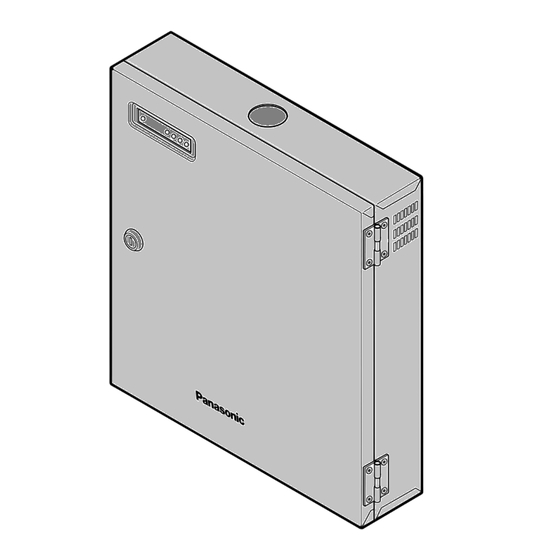
MAJOR OPERATING CONTROLS AND THEIR FUNCTIONS I External View POWER ALARM S3 q Door/Key hole You can open the control box door by using the sup- plied key. When you close the door, turn the key coun- terclockwise to lock. Caution: When you open the door with the power on and 10 seconds have passed after your turning on the power and opening the door, the buzzer will... - Page 11 G Setting board POWER ALARM S3 – DSW1 DSW2 CN503 CN504 q Door sensor Detects the door opening or closing. When you open the door with the power on or 10 seconds have passed after your turning on the power and opening the door, the buzzer will beep to notify the administration PC that the door is open.
-
Page 12: Power Board
G Input/Output Board CN903 CN901 GATE 1 GATE 2 ALARM IN ALARM OUT CAMERA 3 CAMERA 2 CAMERA 1 CN904 q Gate control I/F connectors An electric lock is connectable to the GATE 1 connec- tor. Wiegand/RS-485 Interface is connectable to the GATE 2 connector. -
Page 13: Installations And Settings
* The use of door control box was not evaluated by UL. * General-purpose power supply must be a UL Listed access control power limited device. Coaxial cable (BNC) Camera power cable BM-ED500 POWER ALARM S3 Camera 1 Camera 2... -
Page 14: I Preparation
I Preparation Prepare the following items before the installation. The necessary items and their lengths differ depending on condition. G Preparing the necessary items Item DC power cable Coaxial cable LAN cable Anchor bolt Unicorn anchor Flexible Metal Conduit (According to NEC) Total area: 823.9 mm /100 % {1.277 in. -
Page 15: I Installation
I Installation The following is the procedure to mount the control unit over the wall with the supplied mounting bracket. When mounting, follow the procedure. After mounting the plate, secure the control unit to the mounting plate. Otherwise, it may drop and cause damage or injury. - Page 16 2. Pass the DC power cable through the upper cable holes, and then mount the control unit over the wall. Make two holes to attach the supplied bushing or a flexible metal conduit described in the figure. Use a metal conduit. Cable holes Use a metal conduit.
- Page 17 4. If you make the control unit output alarm signals to external devices and relate them to the alarm signals from the iris cam- eras or the control unit, connect the devices to ALARM OUT 1 to 8. For example, you can start alarm-related recording by connecting ALARM OUT and a recorder’s alarm input connector.
-
Page 18: Settings
SETTINGS I Description To use the control unit, the following settings are necessary with the setting switches or numeric buttons on the setting board. • Setting/confirmation of the operation mode/IP address (Operation mode switches) • I/F type setting (DSW1) You will set the I/F of the control unit (Electric lock I/F, Wiegand out I/F, and RS-485 out I/F). - Page 19 G IP address/Subnet mask/Gateway setting The following are the factory default settings of IP address, subnet mask, and default gateway. IP address: 172.27.1.2 Subnet mask: 255.255.255.0 Gateway: 172.27.1.254 Note: You need to change these addresses depending on the classification or condition of LAN, which connects the control unit.
- Page 20 G Electric lock Setting You can set the lock existence or types of electric locks with DSW 2. Electric lock: This is an electric lock which is connected to the GATE 1 connector. The factory default setting is shown in the figure. Electric lock: Existence and type of the electric lock Do not change these positions.
-
Page 21: Operating Procedures
OPERATING PROCEDURES I Turning the Power On Power switch is inside the control unit. To turn the power on, open the door with the supplied key, and then press the power switch. Close the door within 10 seconds after turn- ing on the control unit. -
Page 22: I When The Door Trouble Is Automatically Unrecoverable
I When the Door Trouble is Automatically Unrecoverable When trouble has occurred to the door and it is automati- cally unrecoverable, ALARM and S3 light up to inform you of the trouble status. In this case, turn off and turn on the power again. -
Page 23: Additional System Components
ADDITIONAL SYSTEM COMPONENTS I Iris Camera BM-ET500 ACCEPT REJECT READY This product is used for recognition/enrollment of iris data. ID-and-password authorization is also available. I Administration Software BM- ES500E Administration Software BM-ES500E This product is necessary to administer iris data, ID data, and passwords. -
Page 24: Specifications Of Electrical Lock Connectors (Gate 1)
SPECIFICATIONS OF ELECTRICAL LOCK CONNECTORS (GATE 1) Port No. – – – – SPECIFICATIONS OF WIEGAND OUTPUT/RS-485 OUTPUT (GATE 2) Port No. – * Port 4 and 7 are not required for operation of this unit or iris camera. They are for wiring designation convenience only. Signal Description Lock control Lock control GND... -
Page 25: Specifications Of Alarm Output Connectors (Alarm Out)
SPECIFICATIONS OF ALARM OUTPUT CONNECTORS (ALARM OUT) Port No. Signal Description Alarm output 1 – Alarm output 1 (GND) Alarm output 2 – Alarm output 2 (GND) Alarm output 3 – Alarm output 3 (GND) Alarm output 4 – Alarm output 4 (GND) Alarm output 5 –... -
Page 26: Troubleshooting
TROUBLESHOOTING Check the following before requesting repair. If a trouble cannot be corrected even after checking and trying remedy, contact your dealer. Problem POWER does not light up. External devices (such as electric locks) do not work. Check item Power may not be supplied to the AC power cord. -
Page 27: Specifications
SPECIFICATIONS General Power source: Power consumption: Ambient operating temperature: Ambient operating humidity: Dimensions: Weight: Input/Output/Interface Iris camera interface: Camera power output: Ethernet port: Electric lock interface: Wiegand interface: RS-485 interface: Alarm output: STANDARD ACCESSORIES Operating instructions (This document)* ... 1 pc. Key* ... - Page 28 Unit of Matsushita Electric Corporation of America Security Systems Group www.panasonic.com/cctv Executive Office: One Panasonic Way 3E-7, Secaucus, New Jersey 07094 Zone Office Eastern: One Panasonic Way, Secaucus, NJ 07094 (201) 348-7303 Central: 1707 N.Randal Road, Elgin, IL 60123 (847) 468-5205 Western: 6550 Katella Ave., Cypress, CA 90630 (714) 373-7840...