
Related Manuals for Panasonic Aquarea PAW-HPM1


Summary of Contents for Panasonic Aquarea PAW-HPM1
- Page 1 Panasonic Aquarea Heat Pump Manager (HPM) Manual Part 1: Installation and Commissioning Aquarea Heat Pump Manager (HPM) 2014...
- Page 2 Notes:...
- Page 3 The copyright of this manual remains with the manufacturer. No part of this manual may be reproduced or processed using electronic systems, or distributed in any form without the written consent of Panasonic Marketing Europe GmbH. Infringements, which contradict the above-mentioned information, makes you liable for damages. All trademarks mentioned in this manual are the property of the respective manufacturers and are hereby acknowledged.
-
Page 4: Table Of Contents
Table of Contents General Information and Safety Notices ............About this Manual ....................... Products covered ........................ Intended Use........................Target Groups ........................Structure and Meaning of Notices ..................Safety Notices ........................Brief Instructions for the User ................Easy Setup Overview ................... Scope of Delivery and Accessories .............. - Page 5 Installation and Terminal Assignments ............. Installation ........................... 7.1.1 Wall Installation ......................7.1.2 Control Cabinet Installation ..................7.1.3 Rail Installation ......................Terminal Assignment ......................7.2.1 Mains voltage ......................7.2.2 Inputs ........................7.2.3 0–10V Inputs/Outputs (Universal terminals) ............. 7.2.4 Outputs ........................7.2.5 Connections of the Heat Pumps ................
-
Page 6: General Information And Safety Notices
● PAW-HPM2 Intended Use The HPM controller is available as an accessory for Panasonic AQUAREA heat pumps and is exclusively intended for the control of heating and hot water systems including Panasonic AQUAREA heat pumps. Adherence to the instructions in this manual, especially the safety notices, is required for the intended use. -
Page 7: Structure And Meaning Of Notices
General Information and Safety Notices Structure and Meaning of Notices Safety Notices WARNING Indicates a possibly dangerous situation. If not avoided, death or severe irreversible injuries can be the consequence. CAUTION Indicates a possibly dangerous situation. If not avoided, minor or slight reversible injuries can be the consequence. -
Page 8: Safety Notices
General Information and Safety Notices Text representations ► indicates an operating step; a sequence with several operational steps must be executed in the order specified indicates the result of an operating step ● indicates a list [Button] indicates the name of a button Option indicates an option of the HPMtool or the HPM controller Menu »... -
Page 9: Brief Instructions For The User
Brief Instructions for the User Brief Instructions for the User Important notice This Chapter is mainly intended for the end-user of the heating system. Only the most important user functions and settings are described in the brief instructions. ► Installation and commissioning may only be carried out by qualified technicians. The information and procedures required for this are described in Chapter 3 to 10. - Page 10 Brief Instructions for the User Operating mode switch: Select operating mode of the system In the menu for the operating mode switch, the operating mode for the heating circuit, the domestic hot water circuit and the heat source can be set. The following parameters are shown here: ●...
- Page 11 Brief Instructions for the User System Survey: viewing and adjusting important parameters The system survey provides a quick overview of the current state of the system (operating state, fault state and setpoint / current values of respective system parts) and an option for adjusting the following setpoints: ●...
- Page 12 Brief Instructions for the User Maintenance/acknowledgement: acknowledge faults and start maintenance operation If a fault occurs, a fault message is shown on the display alternating with the basic display. The fault message can be reset (“acknowledged”) in the maintenance/acknowledgement menu and the maintenance function can be started.
- Page 13 Brief Instructions for the User MCR-BMS menu: adjust setpoints In the MCR-BMS menu, the most important parameters and setpoints of the heating circuits and domestic hot water circuits can be changed after entering the access code 1111 (operator). Procedure to change the setpoints(short): ►...
- Page 14 Brief Instructions for the User Procedure to set occupation times (short): ► Starting from the basic display: Enter access code 1111 (→ Access codes (Brief Instructions), P. 12). [OK] ► Starting from the basic display: Press the button. [▼] ► Using the button in the MCR-BMS menu, select the Timers sub-menu and [OK] confirm by pressing the...
-
Page 15: Easy Setup Overview
Easy Setup Overview Easy Setup Overview Important notice This chapter is exclusively intended for qualified technicians with the necessary experience in dealing with the HPM controller. It contains only the most important commissioning steps and settings to enable the experienced installers rapid commissioning. It should not be addressed without reference to the following chapters, since they contain important notes about the commissioning process and for selecting the optimal parameter values. - Page 16 Easy Setup Overview Step 4 Perform settings for “Heat pump”¹ Name Information text Standard Remark setpoint maxSP maximum setpoint 70 °C accept this value when activating therm. disinfection boost.hCu Heating circuits boost 0 °C gradually adapt this value when pulsing the heat pump BoosterH Domestic hot water E-heating must be activated for the therm.
- Page 17 Easy Setup Overview Step 6 Perform settings for “Domestic hot water” Name Information text Standard Remark setpoint SP-OT1 Setpoint OT1* 50 °C is always used when no other tem- perature setpoints for domestic hot water are available or apply. SP-OT2 Setpoint OT2* 50 °C Use during timer function...
- Page 18 Easy Setup Overview Step 7 Perform settings for “Heating circuit”¹ Name Information text Standard Remark setpoint Room com- 0: no; 1: Thermostat; 2: Ed- pensation Sensor/SP-poti if 7-1 room compensation = 1 (room thermostat installed): 7-1.1 system System main switch Assign terminal: terminal 25 or 26 if 7-1 room compensation = 2 (room thermostat installed): 7-1.2 room...
- Page 19 Easy Setup Overview Continue Step 7¹ (continued from previous page) Name Information text Standard Remark setpoint cooling 0: no 1: Automatic 2: demCool 3: 1+2 if 7-8 cooling = 1 (Automatic): 7-8.1 SP-cool Cooling setpoint 16.0 °C 7-8.2 threshOT Release limit outside tempera- 24.0 °C Start cooling mode at 24 °C ture...
- Page 20 Easy Setup Overview Step 9 Open “Extended configur.” menu To open the Extended configuration menu, access level 3 (technician) with access code 4444 and above is required (→ Access Codes, P. 36). Approach (short): [OK] [–] ► Basic Display» keep button pressed » with the button enter [OK] the Access code 4444 »...
- Page 21 Easy Setup Overview Continue Step 9 Perform settings for “Solar system + Domestic hot water tank” (if available) Name Information text Standard Remark setpoint solColl Solar collector temp. Assign available input terminal (17 - 24) e.g. terminal 24; solTank Solar tank temp. optional: assign solar buffer sensor (otherwise: DHW tank sensor);...
- Page 22 Easy Setup Overview Continue Step 9 Perform settings for “Add. heat source + buffer tank” (if available) Name Information text Standard Remark setpoint 9-21 addHS-Fl FlowTemp. addHS Assign available input terminal (17 - 24) e.g. terminal 24; 9-22 addHS Add. heat source assign available output terminal: e.g.
- Page 23 Easy Setup Overview Continue Step 9 (continued from previous page) Name Information text Standard Remark setpoint 9-28 dem-DHW Loading domestic hot water 0: no 1: yes 9-29 dem-DHW Domestic hot water demand 50 °C Indicate setpoint 9-30 dem-HC Buffer loading heating 0: no 1: yes 9-31 dem-HC...
-
Page 24: Scope Of Delivery And Accessories
Scope of Delivery and Accessories Scope of Delivery and Accessories Scope of Delivery The standard scope of delivery of the HPM package consists of the components listed in the table. Overview of the standard scope of delivery Component Description Illustration* Controller HPM1 Controller with operating elements: Use of single controller or master controller (in... -
Page 25: Accessories
Scope of Delivery and Accessories Accessories Depending on the configuration of the heating system, the necessary adapter cables and sensors must be selected from the HPM product range and be ordered separately. Important notice When selecting the adapter cable, the list of communication-capable AQUAREA heat pumps must be observed (→ Communication-capable Aquarea Heat Pump Types, P. 115). Overview of the HPM accessories Accessories Description... -
Page 26: Technical Data
Technical Data Technical Data Dimensions, power supply, temperatures, connections Dimensions (W x H x D) 146.7 x 97.6 x 76 mm Power supply 85 to 265 V AC / 1 Ph / 50/60 Hz Power consumption (depending on max. 8 VA version) Ambient temperature 0 to 50 °C... - Page 27 Technical Data Interfaces Interface designation Connection Application ext. Display RJ-11 socket Connection of the external display PAW-HPMED BUS* Bus terminal Communication with heat pumps Ethernet socket Ethernet or TCP/IP network connection Micro-USB port Connection to PC (Service) * An additional adapter cable (PAW-HPMINT-x) is required for communication with the heat pump via the BUS interface → HPM accessories, P.
-
Page 28: Technical Description
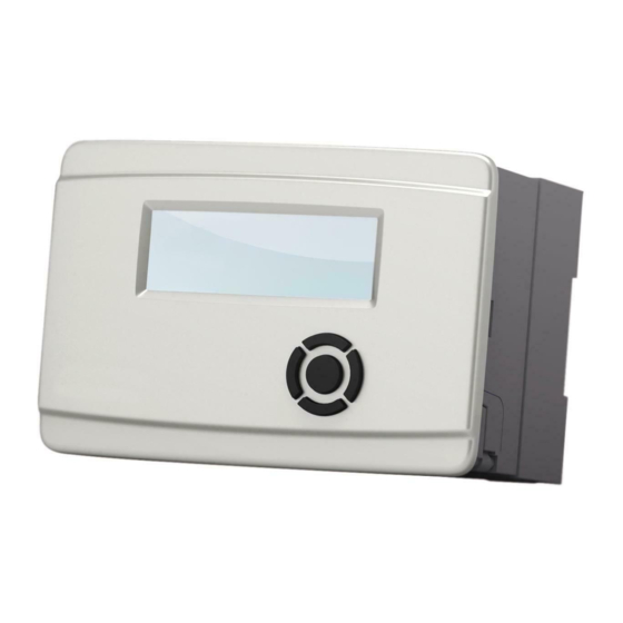
The Aquarea Heat Pump Manager from Panasonic (short: HPM) is a controller for heating and hot water applications. It is offered by Panasonic as an accessory to control Aquarea heat pumps in heating systems with or without additional heat source, domestic hot water tanks and/ or solar heat systems. - Page 29 Technical Description HPM1 model The HPM1 model has a back-lit text display (1) with 4 lines of 20 characters and five buttons (2 – 6) for navigation and to operate the controller. The HPM1 can be used as follows: ● As an independent controller for one to three heat pumps with control via contact release ●...
-
Page 30: Base
Technical Description Application of the HPM models The use of the two HPM models depends on the number of heat pumps in the heating system and the control mode, as shown in the following table. Number of heat pumps Control via contact release Control via communication 1 x HPM1 1 x HPM1... - Page 31 Technical Description The distributors in the extra-low voltage area (2) is used for the sensor ground. The distributors in the low voltage area are for the PE conductor (protective earth) (4) and the neutral wire (N) (5). There are pre-cut cable openings on the top and bottom of the base. Disconnecting the controller from the base WARNING Electric shock from electrical voltage!
-
Page 32: Interfaces
Technical Description Attaching the controller to the base WARNING Electric shock from electrical voltage! The device is operated using 230 V AC voltage: Danger to life from electric shock by contact with conducting parts. ► Switch off power supply, prior to attaching the controller to the base. Prior to the installation, the controller must be attached to the base as follows: ►... -
Page 33: Interface "Ext. Display
Technical Description 6.4.1 Interface “ext. Display” This interface (1) is labelled in the terminal connection diagram on the rear of the controller with the description “ext. Display“. The interface is exclusively used to connect the external display with the touch screen (PAW- HPMED). -
Page 34: Usb" Interface
● USB driver ● HPM service programs (HPMcontrol/read/write) These components are not included in the HPM scope of supply. The HPM service programs and the USB driver can however be provided on request from Panasonic. Operating Elements The HPM1 model operating controls consist of a display and five buttons. The elements of the display and the functions of the buttons are explained in more detail in the following chapters. -
Page 35: Buttons
Technical Description The elements of the basic display are set ex-factory and show the most important information for the user. The elements of the basic display can be customized by qualified technicians (→ Modify Basic Display, P. 45). Fig. 6.6: Elements of the basic display Time Status for WEB interface Week day HPM model Date Maintenance function (here, none is shown) Operating mode switch 6.5.2 Buttons... -
Page 36: Operating Functions
Technical Description Function of buttons in the menu structure In the menu structure, the buttons are used for navigation, to enter or select values and to confirm settings. navigate up within a menu level or 1 Button [▲] (up) change from the top entry of a menu level to the next higher level [–] Reduce value or scroll backwards through a value list 2 Button... - Page 37 Technical Description Overview of the access codes There are 4 different access levels. The scope of the access rights is based on the tasks and the knowledge of the respective user. Access level Scope of access rights Standard access code 1: User Minimum operation: No code required...
- Page 38 Technical Description Overview of the menu structure Main menu “Source functions” Sub-menu level... Global MCR-BMS (Shortcut: [OK] button Timers Heat source Heat pump 1 Heat pump 2 Heat pump 3 Strategy circuit Buffer tank Domestic hot water Heating circuits Heating circuit 1 Heating circuit 2 Trend Trend 1...
-
Page 39: Operating Mode Switch (Shortcut: Button [+])
Technical Description 6.6.2 Operating Mode Switch (Shortcut: button [+]) In the menu for the operating mode switch, the operating mode for the heating circuit, the domestic hot water circuit and the heat source can be set. Opening the menu for the operating mode switch: ►... - Page 40 Technical Description CAUTION Damage of the heating system due to freezing! In the Off switch position the frost protection mode is deactivated, meaning there is no pump or valve operation. In this case, the heating system can freeze during low outside temperatures. ►...
-
Page 41: System Survey (Shortcut: Button [-])
Technical Description Switch positions Switch position Manual cooling Auto Heating operation; automatic switching of the heating circuits to cooling mode when the outside temperature is above the set threshold threshOT (Standard setpoint 24 °C) and cooling mode is activated (Cooling active = 1) The heating circuits are switched manually in the cooling mode (regardless of the outside temperature and also during deactivated cooling operation (Cooling active = 0) -
Page 42: Party Functions (Shortcut: Button [▼])
Technical Description Retrieving information about a specific parameter in the menu for system survey ► Open parameter as described before. [OK] ► Press the button. The following information about the parameter is displayed: Brief descriptions, long descriptions and parameter number. [▲] ► Press the button to return to the parameter settings display. The parameter is again marked by an arrow (→) and shown on the display. -
Page 43: Maintenance/Acknowledgement (Shortcut: Button [▼])
Technical Description 6.6.5 Maintenance/Acknowledgement (Shortcut: button [▼]) If a malfunction or fault occurs, a fault message is shown on the display, alternating with the basic display. The maintenance/acknowledgement menu provides the following options for this case: ● Resetting fault messages ●... - Page 44 Technical Description Opening the menu for MCR-BMS: [OK] ► Starting from the basic display: Press the button. The MCR-BMS menu is shown. Example: Changing setpoints for the individual consumer circuits in the MCR-BMSmenu. [▼] ► Using the button in the MCR-BMS menu, select the desired consumer circuit (domestic hot water, heating circuits »...
-
Page 45: Modify Basic Display
Technical Description 6.6.7 Modify Basic Display The elements of the basic display may only be changed by qualified technicians. To access the menu to change the basic display, access level 4 (service) with the access code 4 5555 is required (→ Access Codes, P. 36). The elements of the basic display can be changed as follows. [OK] ►... -
Page 46: Installation And Terminal Assignments
Installation and Terminal Assignments Installation and Terminal Assignments Installation WARNING Electric shock from electrical voltage! The device is operated using 230 V AC voltage: Danger to life from electric shock by contact with conducting parts. ► Switch off power supply prior to starting the installation. The controller must be disconnected from the base prior to installation (→ Disconnecting the controller from the base, P. -
Page 47: Control Cabinet Installation
Installation and Terminal Assignments 7.1.2 Control Cabinet Installation The HPM can to be installed on the mounting plate of a switch cabinet or a conventional heat source (if available). The controller fits in a recess opening with DIN dimensions (138 x 192 mm). It is installed as follows: ► Push the controller through the recess opening in the mounting plate of the switch cabinetor the conventional heat source. -
Page 48: Terminal Assignment
Installation and Terminal Assignments Terminal Assignment WARNING Electric shock from electrical voltage! The device is operated using 230 V AC voltage: Danger to life from electric shock by contact with conducting parts. ► Switch off power supply prior to starting work on the cable connections. Connections of the HPM controller A terminal connection diagram is provided on the inside of the controller, which can only be seen when the controller is separated from the base (→ Disconnecting the controller from the... -
Page 49: Mains Voltage
Installation and Terminal Assignments Temp.sensor Temp.sensor Temp.sensor Potential for 13 Temp.sensor Relay output Temp.sensor not used Temp.sensor Relay output Temp.sensor Potential for 9+11 Temp.sensor Relay output Meter/contact not used Meter/contact Relay output 0...10V Potential for 5+7 0...10V Relay output Ground for 17-28 not used not used Relay output... -
Page 50: Inputs
Installation and Terminal Assignments Important notice If the potential-free relay contacts should switch the same potential as the mains voltage, then select the following connection types depending on the control mode of the heat pumps: ► When controlling via communication, clamp the control phase L of the supply voltage to the input terminals of the potential-free relay contacts (terminals 2, 6, 10, 14), as long as components are connected to it. - Page 51 Installation and Terminal Assignments Sensor/ contact Temp.sensor Temp.sensor Temp.sensor Potential for 13 Temp.sensor Relay output Temp.sensor not used Temp.sensor Relay output Temp.sensor Potential for 9+11 Temp.sensor Relay output Meter/contact not used Meter/contact Relay output 0...10V Potential for 5+7 0...10V Relay output Ground for 17-28 not used not used...
- Page 52 Installation and Terminal Assignments The room temperature sensor PAW-HPMR4 with remote setpoint transmitter can be connected to all sensor inputs that are, after loading of the system diagram (→ Loading the system diagram in the HPM controller, P. 68), still without function. Sensor and setpoint transmitters are each connected to the terminal which is assigned to them, and to the sensor ground.
-
Page 53: 0-10V Inputs/Outputs (Universal Terminals)
Installation and Terminal Assignments Notice In the Photovoltaics menu, the calculated current output such as virtual contact inputs (“terminals 35 and 36") will be handled and used for ascertaining an energy surplus (→ Photovoltaics, P. 84). Room thermostat (to switch off the heating circuit) A room thermostat can be used to switch off the heating system. -
Page 54: Outputs
Installation and Terminal Assignments External demand Sensor Sensor Sensor Sensor Sensor Sensor Sensor Potential Sensor Potential Sensor Potential Sensor Relay Sensor Relay Sensor Relay Sensor not used Sensor not used Sensor not used Sensor Relay Sensor Relay Sensor Relay Sensor Potential Sensor Potential... - Page 55 Installation and Terminal Assignments Valves The correct connection of valve actuators is illustrated by the following terminal assignment plans. Valve with 2-point control (thermal actuators or damper actuators) Temp.sensor Temp.sensor Temp.sensor Potential for 13 Temp.sensor Relay output Temp.sensor not used Temp.sensor Relay output Temp.sensor...
- Page 56 Installation and Terminal Assignments Valves with 3-point control Temp.sensor Temp.sensor Temp.sensor Potential for 13 Temp.sensor Relay output Temp.sensor not used Temp.sensor Relay output Temp.sensor Potential for 9+11 Temp.sensor Relay output Meter/contact not used Meter/contact Relay output 0...10V Potential for 5+7 0...10V Relay output Ground for 17-28...
- Page 57 Installation and Terminal Assignments Pumps The correct connection of the pumps is illustrated by the following terminal assignment plans. Pumps with 2-point control (On/Off) Temp.sensor Temp.sensor Temp.sensor Potential for 13 Temp.sensor Relay output Temp.sensor not used Temp.sensor Relay output Temp.sensor Potential for 9+11 Temp.sensor Relay output...
-
Page 58: Connections Of The Heat Pumps
The connections and functions are shown in the following illustration. Fig. 7.17: External connections of a Panasonic Aquarea heat pump and its functions 2-way valve Tank sensor... - Page 59 Installation and Terminal Assignments For the connection of the heat pump the following criteria are important: ● Number of heat pumps: Individual heat pump or cascade with 2 or 3 heat pumps ● Application (only for individual heat pumps): only for heating or for heating system and domestic hot water Overview of the connection criteria during contact release Single heat pump...
- Page 60 Installation and Terminal Assignments Heating only Heating + domestic hot water Fig. 7.18: Individual heat pumps with control via contact release HPM1: HPM1: SD No. 10xxx / 1 HP / Contact release SD No. 17xxx / 1 HP / Contact release Heat pumps: Heat pumps: Terminals 17 + 18 / heating only...
- Page 61 Installation and Terminal Assignments Fig. 7.19: Cascade with control via contact release HPM1: SD No. 3xxxx / 3 HPs / contact release Heat pump 2: terminals 17 + 18 / for heating only / Router (optional) follows Connection to the internet Heat pump 3: terminals 17 + 18 / for heating only / Heat pump 1: terminals 9 + 12 / Heating + domestic leads...
- Page 62 Installation and Terminal Assignments Connection when controlling via communication When controlling via communication, the complete function range of the HPM controller can be used. With this type of control, the HPM completely replaces the control panel of the heat pump. This means that all settings for the heat pump, the heating circuit, the domestic hot water tank and/or the solar system (if available) can be performed or changed via the HPM.
- Page 63 Installation and Terminal Assignments Fig. 7.20: Adapter cable plug-ins (sockets) on the printed circuit board of the heat pumps Printed circuit board of the compact heat pumps Printed circuit board of the split heat pumps Slot for adapter cable (here with cable attached to Slot for adapter cable (here with cable attached to the control panel) the control panel)
- Page 64 Installation and Terminal Assignments Fig. 7.21: Cascade with control via communication HPM1: Master (.11) / HP1 / HPM2: Slave (.13) / HP3 / SD-No. 7xxxx / 3 HPs / communication SD-No. 90000 / 3 HPs / Communication Ethernet switch Connection to the internet HPM2: Slave (.12) / HP2 / Heat pump 1 / Heating + Heating + domestic hot SD-No.
-
Page 65: Commissioning
The controller is pre-programmed with about 600 system diagrams to simplify the configuration. When commissioning, the appropriate system diagram will be loaded for the respective heating system in the HPM controller and adjusted if necessary. For selecting the system diagram, Panasonic provides the HPMtool as web-based software at www.hpmtool.eu Commissioning is done in the following steps: ●... - Page 66 Commissioning The HPMtool is available in the German, English, French, Spanish and Italian languages. The menu for language selection is located at the top right of the screen. When changing the language, the system diagram selection does not change. ► In the Heat pump, domHotWater , buffer tank, heatC. 1 and heatC. 2 menus, select the components of the desired heating system.
- Page 67 Commissioning Notice Non-permissible combinations are shown in the menu window in light grey. Fig. 8.3: HPMtool – System diagram The symbol next to the SD number indicates if the selected system diagram is available. : System diagram not available : Delete current system diagram and start again with the selection : System diagram available If there is no system diagram available that meets the actual heating system: Select a scheme as similar as possible and manually adjust the deviant heating system parameters during...
-
Page 68: Loading The System Diagram In The Hpm Controller
● Manual configuration (if no suitable system diagram is available) This method, however, is significantly more time-consuming, complex and error prone and is therefore not recommended for commissioning. Recommended method To configure the HPM controller, Panasonic recommends the “Easy setup“ since this is the fastest and most dependable method. With this method, the HPM takes over the parameter configuration of the selected system diagram, but the user can adjust the standard setpoints of the most important parameter for the respective heating system. This has the advantage that the configuration of the controller is... - Page 69 Commissioning Start: Configuration of the HPM controller Initial loading? → Initial loading, → Repeat loading, P. 70 P. 77 Select display language Open system diagrams menu Load SD number from → Manual Configu- HPMtool? ration, P. 89 • sysDiagram = 99999 (= Manual configuration), •...
-
Page 70: Initial Loading
Commissioning Important notice No complete configuration during power supply interruption! The configuration will not be completed during power interruptions and the automatic configuration must be performed again (→ Repeat loading, P. 77). 8.2.1 Initial loading The HPM controller detects at switch-on whether a system diagram is loaded or not. The user is prompted to select the display language and scheme, if no system diagram is loaded. Procedure during initial loading Switching on controller and selecting display language ►... - Page 71 Commissioning Load system diagram, Set sensor type, Indicate heat pump types [–] ► Using the buttons, select the SD number that was determined by the HPMtool. [OK] ► Press the button to confirm the entered SD number. [▼] ► Using the button, select the typeSensor parameter to indicate the sensor type.
- Page 72 Commissioning Activating Easy setup [▼] ► Using the button select the easySetup parameter. easySetup = 1: easy setup activated The easy setup allows the most important parameters to be modified (→ Parameters available for the easy setup, P. 73). The available parameter for the easy setup are shown directly under the easySetup parameter and can [–] [OK] be adjusted using the...
- Page 73 Commissioning Parameters available for the easy setup The parameters provided in the following tables are available for the easy setup. These parameter are only shown, if theeasySetup = 1 parameter is set. These parameter are not shown, if theeasySetup = 0 parameters are set. Which parameter is shown depends on which system diagram has been selected and which heat pump types are indicated.
- Page 74 Commissioning Strategy Name Information text Unit St-SP Min. Max. Remark Strategy (only when more than 1 HP in system) leading Lead change 1 Running time-dependent lead change? 0: no; 1: yes running time Change in lead after running 10 10,000 Running time difference for switching the lead time sequHC Heat source - sequence...
- Page 75 Commissioning Domestic hot water Name Information text Unit St-SP Min. Max. Remark Domestic hot water SP-OT1 Setpoint OT1 °C 45.0 160.0 Tank setpoint for occupation time 1 SP-OT2 Setpoint OT2 °C 45.0 160.0 Tank setpoint for occupation time 2 SP-NO Setpoint NO °C 160.0 Tank setpoint for non-occupation time...
- Page 76 Commissioning Heating circuits 1 and 2 Name Information text Unit St-SP Min. Max. Remark Heating circuit 1 Room compen- 0: no; 1: Thermostat; 2: 2 Optimization of the heating via the room sation EdSensor/SP-poti thermostat (shutdown) or room temp sensor (VL-SW Corr) system System main switch...
-
Page 77: Repeat Loading
Commissioning 8.2.2 Repeat loading The system diagram can be reloaded at any time. This may be necessary if, for example, the configuration of the controller could not be carried out completely due to a power failure or another system diagram should be selected. Procedure for reloading Open the “System diagrams” menu [OK] ► Starting from the basic display: Keep pressing the button until the prompt to enter the access code is shown. - Page 78 Commissioning [▼] button select the easySetup parameter. ► Using the easySetup = 1: easy setup activated The easy setup allows the most important parameters to be modified (→ Parameters available for the easy setup, P. 73). The available parameter for the easy setup are shown directly under the easySetup parameter and can [–] [OK] be adjusted using the...
-
Page 79: Extended Configuration
Commissioning 8.2.3 Extended Configuration Using the parameter of the extended configuration, the settings can be further adapted to the loaded system diagram. This may be necessary if the heating system differs from the system diagram or will be expanded at a later point. The adjustments can be made during commissioning or during operation. The “Extended Configuration” menu is however not freely accessible to all users, but must be released by entering the access code. - Page 80 Commissioning Parameter for extended configuration Menu Functions Description, terminal assignment and settings Extended configur. HCu1 room compensation Optimization of the heating circuits by the switching on room thermostat, room temp sensor and remote HCu2 room compensation setpoint transmitter HP Bivalence Boiler release (alternative/parallel) during outside temperatures below the limit or demand Strategy addHS...
- Page 81 Commissioning The reduction in the flow temperature prevents overheating of the reference room in which the room temperature sensor is installed. The room temperature setpoint is set at the setpoint potentiometer, which is integrated in the area sensor / remote setpoint (PAW HPMR4) transmitter. Depending on the selected mode, the parameters for the assignment of the inputs are displayed.
- Page 82 Commissioning additional heat source to support the heat pumps, after the last heat pump has been enabled by the sequential switching. After assigning a relay output, the switch on and switch off delays for the release and locking of the add. heat source can be set. After the terminal assignment, the function is activated.
- Page 83 Commissioning Buffer Solar This function is displayed, if a system diagram with buffer tank was loaded for the heating water. The function controls the solar pump output if the temperature difference between the collector and the buffer is sufficient. After assigning an input terminal for the solar collector sensor, the parameters listed below are displayed and can be adjusted as required. The relay output via which the pump is to be switched, must be assigned as solar pump (SolPu).
- Page 84 Commissioning After assigning the input for the addHS feed temperature and the output for the addHS (pump output), the function is activated. Name Information text Unit St-SP Settings addHS-Fl Solar collector temp. 0 Assigning a sensor input 17–24 addHS Solar pump 0 Assigning a relay output 1–13 tDiffOn Temp.
- Page 85 Commissioning The function is activated after setting the type-Pv parameter and assigning the required inputs. Name Information text Unit St-SP Settings type-Pv 1: contact 2: output 1 Select type, i.e. reaction to 1: contact 3: Dyn. output release, 2+3: calculated excess energy (generated - used), whereby 2: set minDiff- Cap, 3: dynamic minDiffCap rel-pv...
- Page 86 Commissioning Smart Grid With this function, the system can be integrated into a smart grid. The electric supply company (ESC) can influence the currently valid operating status of the system, via control signals (two signal contacts Inp1 and Inp2). Depending on the loaded system diagram, the release and setpoints of the heat pumps, domestic hot water tank and buffer tank can be influenced. An example for the use of the Smart Grid function is the electric supply company restriction where the electric supply company (ESP) can externally restrict the heat pump operation, e.g.
- Page 87 Undertake the required wiring ► When wiring the heat pump, a jumper is required at terminals 17 and 18 (→ External connections of a Panasonic Aquarea heat pump, P. 58 (Fig. 7.17)). ► When wiring the HPM controller, connect the lines for the electric supply company restriction signals to terminal 25 and ground (→ Connecting counters...
-
Page 88: Resetting The Hpm Controller
Commissioning Assign signal inputs to certain terminals [OK] ► Starting from the basic display on the HPM controller: Press and hold the button, until the prompt to input the access code appears. [–] ► Using the buttons, enter access code 4444 (technician). [OK] ►... -
Page 89: Manual Configuration
Commissioning [–] buttons, enter the SD number 00000 ► Using the [OK] ► Confirm using the button. [▼] ► Using the button, select the cold start parameter. [OK] ► Using the button, set the parameter to 1 and confirm with the button. ► Watch the display until the prompt to enter the display language appears. The delivery state of the HPM controller is restored. - Page 90 Commissioning Load system diagram, set sensor type, indicate heat pump type [–] ► Using the buttons, enter the SD number 99999 [OK] ► Confirm using the button. [▼] ► Using the button, select the typeSensor parameter to indicate the sensor type. Changing the factory setting 0 is only necessary when using other sensors. A [–] calibration to 1:Ni1000 or 2:Ni1000LG can be done by using the buttons.
- Page 91 Commissioning Enter further control circuits [▼] ► Using the button, select the Buffer (buffer tank) parameter, adjust as [–] required using the buttons and confirm the setting by pressing the [OK] button: 0 = no buffer tank available 1 = buffer tank available [▼] ► Using the button, select the num-DHW (domestic hot water circuit) [–] parameter, adjust as required using the...
-
Page 92: Advanced Settings
Commissioning Advanced Settings Should the standard setpoints be accepted unchanged during loading of the system diagram (e.g. w/o Easy setup, easySetup= 0), then further settings must be performed on the HPM controller after the configuration. The following settings are required: ● Settings to adjust the controller to the communication connection with the heat pumps (basic settings) ●... -
Page 93: Heat Source - Strategy
Commissioning [▼] [OK] button, select the Function sub-menu and confirm with ► Using the [▼] ► In the Function menu and using the button, select the area Aquarea [OK] ► Confirm using the button. [▼] ► Using the button in the Aquarea menu, select the Settings sub-menu. [OK] ►... - Page 94 Commissioning The lead change between the heat pumps can either be triggered via the running time or via fault switching of the heat pumps. leadingA lead change takes place, if the number of operating hours of the lead heat pump is greater by the value of the Running time (in menu MCR-BMS»...
-
Page 95: Buffer Tank - Setpoints
Commissioning 8.3.3 Buffer tank – setpoints Control of a buffer tank with one zone is possible using the HPM. In the MCR-BMS» Buffer tank» Setpoints menu, the currently calculated buffer tank temperature (parameter SP-zone1) is shown. The value is calculated from the demand of internal heating circuits, domestic hot water circuit and the external consumers. -
Page 96: Heat Circuits - Setpoints, Heat Characteristic, Setpoint Limitation
Commissioning Procedure: [OK] ► Starting from the basic display: Press the button to open the menu structure. [▼] ► Using the button in the MCR-BMS menu, select the domestic hot water sub-menu. [OK] ► Confirm using the button. [▼] button, select the Setpoints menu. ►... - Page 97 Commissioning Procedure: [OK] ► Starting from the basic display: Press the button to open the menu structure. [▼] ► Using the button in the MCR-BMS menu, select the heating circuit sub- menu. [OK] ► Confirm using the button. 1 or 2 heating circuits are available depending on the selected system diagram. If more than 1 heating circuit is displayed: [▲] [▼]...
-
Page 98: System - Time And Date
Commissioning Depending on the design of the heating system and the material used, it may be necessary to adjust a setpoint limitation. This causes the calculated flow setpoint (regardless of the selected heating curve) to remain below the set maximum temperature. An adaptation is possible in the Heating circuits» Heating circuit x » Function» Setpoint limitation menu. - Page 99 Commissioning Procedure: [OK] ► Starting from the basic display: Press the button to open the menu structure. [▼] ► Using the button in the MCR-BMS menu, select the Timers sub-menu. [OK] ► Confirm using the button. [▼] ► Using the button, select the Timer channel selection submenu. [OK] ►...
- Page 100 Commissioning Example 2: Loading with changing opening times Heating circuit 1 should be in operation during the opening times of the storing; the non- occupation period applies outside the opening times. Opening hours: Monday to Friday from 08:00 to 12:00 and from 13:00 to 20:00 hours Saturday from 09:00 to 15:00 hours Closed on Sundays Procedure:...
- Page 101 Commissioning Start and end of the occupation time may not cross over. Day-crossover occupation times can be set by entering two time periods. Example 3: Birthday celebration with day-crossover occupation time from Friday to Saturday Procedure: ► Open timer channel HeatC1 as described before. [▼] ►...
- Page 102 Commissioning In the year programme of the timer channels, a maximum of 15 special non-occupation times (special-non-occup) and a maximum of 10 special occupation times (special-occup.) can be set. By entering the date, operating times for non-occupation and occupation can be defined that differ from the weekly programme. In these cases, the normal weekly programme for a particular day is ineffective.
-
Page 103: Function Check
Commissioning 8.3.8 Function Check To ensure that the commissioning has been successful, the connected sensors are checked and the correct function of the outputs is checked. Function check for sensors If the sensors are connected correctly, their measured values are shown in the curValue sub- menu of the respective heating circuit (Example: sub-menu MCR-BMS »... -
Page 104: Screed Drying
Commissioning [▲] ► Press the button to return to the basic display. [OK] ► Press the button to open the menu structure. [▼] [OK] ► With the buttons, open in the MCR-BMS menu for the respective control circuit the sub-menu manual operation (Example: Sub-menu MCR- BMS»... - Page 105 Commissioning Procedure: [OK] ► Starting from the basic display: Press the button to open the menu structure. [▼] ► Using the button in the MCR-BMS menu, select the sub-menu Heating circuits» heatC. 1 » function » screed drying. [OK] ► Confirm using the button.
-
Page 106: Fault Messages
Fault messages Fault messages The HPM detects error and faults. The error messages are shown in the basic display as short text. The following short texts can be displayed: Short text Explanation Switch not in Auto Operating mode switch is not in Automatic position Error Com. -
Page 107: Appendix
Appendix 10 Appendix 10.1 Heating Characteristics To adjust the weather-dependent calculation of the feed temperature setpoint, the following calculation factors can be changed in the menu MCR-BMS» heatCirc.» heatC. x » setpoints. ● Heating characteristic (slope) – Parameter hCu-slope ● Heating element exponent (curvature) – Parameter hCu-exp ●... - Page 108 Appendix Feed temperature setpoints depending on heating curve parameters and outside temperatures Heating characteristic (Slope) / hCu-slope 22.0 22.0 22.0 22.0 22.0 22.0 22.0 22.0 22.0 22.0 22.0 22.0 22.0 22.0 22.0 22.0 22.0 26.5 26.3 26.0 25.7 25.5 25.2 25.0 24.7 24.5...
-
Page 109: Measured Value Table For Sensors
Appendix 10.2 Measured value table for sensors The HPM controller is factory set for the use of Pt1000 standard resistor sensors. To check a sensor, both wires of the measuring line must be separated from the HPM controller. The temperature-dependent resistance of the sensor can then be measured with a multimeter. The measured value must correspond to the raw value, which is displayed by the HPM, once the sensor has been connected again. -
Page 110: Detailed Menu Structure
Appendix 10.3 Detailed Menu Structure Main menu Global Messages Fault Service Hardware Software Cold/warm start Access codes Project management System clock Structuring Display MCR-BMS Timers Timer current values Timer channel selection “per control circuit” Week programme Special non-occupation periods Special occupation periods Priority Clock status “per control circuit”... - Page 111 Appendix Sub-menu “Heat pump x” Heat pump x Current values HPOutdoor HPOutletTemp HPInletTemp Setpoints setpointHC Heating circuits heating/cooling setp.DHW Domestic hot water demand Function Setpoint limitation Boost Maintenance Signal External demand Controller Bivalence Aquarea Settings Service Mode Bus status Status Operating status, fault status, setpoint source, outputs, help status displays, Aquarea response OP-...
- Page 112 Appendix Sub-menu “Strategy” Strategy Current values FlowHC FlowDHW outdoor Setpoints SP-FlowHC Heating circuits heating/cooling SP-FlowDHW Domestic hot water demand Function Leading Sequence Boost Signal Frost limit Pump Add. heat source external demand Controller Setpoint limitation Blocking protection Status Operating status, fault status, SP source, control output, help status displays Manual operation Pump 0=OFF, 1=ON, 3=AUTO...
- Page 113 Appendix Sub-menu “Domestic hot water” Domestic hot water Current values DHWtank DHWtank2 DHWtank Flow ..Setpoints DHWtank SP-OT1 SP-OT2 etc. Additional function Priority Controller release Return flow limiting Remote control Signal Frost limit Setpoint limitation Controller Forced loading Therm. Disinfection Circulation pump Blocking protection Output limitation...
- Page 114 Appendix Sub-menu “heatC. x” Heating circuit Current values Room (only on room temperature controllers) outdoor Flow Setpoints SP-room (only on room temperature controllers) SP-Flow hCu-slope hCu-exp BaseOT1 SP-cool Cooling setpoint Additional function Summer shutdown HCu Adaptation Setpoint limitation Universal limit Room compensation (only on room temperature controllers) DelayOutsideTemp...
-
Page 115: Communication-Capable Aquarea Heat Pump Types
Appendix 10.4 Communication-capable Aquarea Heat Pump Types When controlling via communication (SD numbers 4xxxx, 5xxxx, 6xxxx or 7xxxx), the type of heat pumps 1 to 3 (if available) must be entered for the type-HP1, type-HP2 and type- HP3 parameters. The type entered here must be exactly identical to the type designation (including service number –1) specified on the type plate of the relevant heat pump (examples: SXC12D90E8-1 or ADC0309G3E5). - Page 116 Appendix Split heat pumps Split heat pumps All in One split heat (older generations) starting from generation “F” pumps Adapter cable Adapter cable Adapter cable PAW-HPMINT-U (3 m) PAW-HPMINT-F (3 m) PAW-HPMINT-F (3 m) High Perfor- T-CAP High Perfor- T-CAP mance mance SDC03E3E5 SXC09D3E5 SHF09D3E5...
-
Page 117: Index
Appendix 10.5 Index Heat pump connection 58 Control types 28 Access code 36, 77, 92 Menu Structure 38 Communication 28 Access level 37 Detailed 110 Contact release 28 Adapter cable 33 Cooling 40 PAW-HPMINT-F 33 Cooling mode 39 Occupation time extension 42 PAW-HPMINT-M 33 Cooling operation 39 Operating elements 34... - Page 118 www.aircon.panasonic.eu...