Siemens SIMATIC NET RUGGEDCOM RSG2100 Installation Manual
Rugged ethernet switches
Hide thumbs
Also See for SIMATIC NET RUGGEDCOM RSG2100:
- Service manual (50 pages) ,
- Installation manual (56 pages)

Related Manuals for Siemens SIMATIC NET RUGGEDCOM RSG2100


Summary of Contents for Siemens SIMATIC NET RUGGEDCOM RSG2100
- Page 1 Edition 11/2022 Installation Manual SIMATIC NET Rugged Ethernet Switches RUGGEDCOM RSG2100 https://www.siemens.com/ruggedcom...
- Page 2 Preface Introduction Installing the Device SIMATIC NET Device Management Rugged Ethernet Switches RUGGEDCOM RSG2100 Communication Ports Technical Specifications Installation Manual Certification 11/2022 C79000-G8976-1040-20...
- Page 3 Note the following: WARNING Siemens products may only be used for the applications described in the catalog and in the relevant technical documentation. If products and components from other manufacturers are used, these must be recommended or approved by Siemens. Proper transport, storage, installation, assembly, commissioning, operation and maintenance are required to ensure that the products operate safely and without any problems.
-
Page 4: Table Of Contents
Accessing Documentation ....................... v Registered Trademarks ......................v Warranty ..........................vi Training ..........................vi Customer Support ........................vi Contacting Siemens ....................... vii Introduction ........................... 1 Feature Highlights ....................1 Description ......................2 Required Tools and Materials ................. 3 Decommissioning and Disposal ................3 Cabling Recommendations .................. - Page 5 Table of Contents GBIC Optic Ethernet Ports ..................27 4.4.1 Installing a GBIC Optical Port ................27 4.4.2 Removing a GBIC Optical Port ................29 Technical Specifications ...................... 31 Power Supply Specifications ................31 Failsafe Relay Specifications ................31 Supported Networking Standards ................ 32 Copper Ethernet Port Specifications ..............
-
Page 6: Preface
SIMATIC NET Glossary The SIMATIC NET Glossary describes special terms that may be used in this document. The glossary is available online via Siemens Industry Online Support (SIOS) at: https://support.industry.siemens.com/cs/ww/en/view/50305045 Accessing Documentation The latest user documentation for RUGGEDCOM RSG2100 is available online at https://support.industry.siemens.com. -
Page 7: Warranty
Preface Warranty Warranty Siemens warrants this product for a period of five (5) years from the date of purchase, conditional upon the return to factory for maintenance during the warranty term. This product contains no user-serviceable parts. Attempted service by unauthorized personnel shall render all warranties null and void. -
Page 8: Contacting Siemens
Call a local hotline center to submit a Support Request (SR). To locate a local hotline center, visit https://w3.siemens.com/aspa_app/?lang=en. Mobile App Install the Industry Online Support app by Siemens AG on any Android, Apple iOS or Windows mobile device and be able to: •... - Page 9 Preface Contacting Siemens viii RUGGEDCOM RSG2100 Installation Manual, 11/2022, C79000-G8976-1040-20...
-
Page 10: Introduction
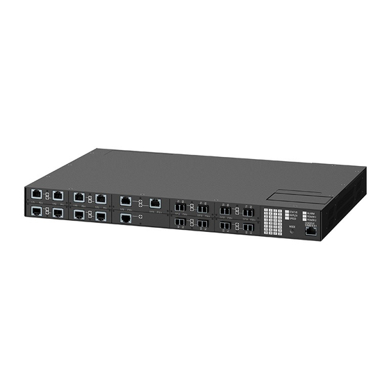
Introduction The RUGGEDCOM RSG2100 is a rugged, fully managed, modular Ethernet switch specifically designed to operate reliably in electrically harsh and climatically demanding utility substation, railway and industrial environments. The RUGGEDCOM RSG2100’s superior rugged hardware design coupled with the embedded Rugged Operating System (ROS) provides improved system reliability and advanced cyber security and networking features, making it ideally suited for creating Ethernet networks for mission-critical, real-time, control applications. -
Page 11: Description
Introduction 1.2 Description Universal Power Supply Options • Fully integrated, dual-redundant (optional) power supplies • Universal high-voltage range: 88-300 VDC or 85-264 VAC • Screw or pluggable terminal blocks for reliable, maintenance-free connections • CSA/UL 62368-1 safety approved to 85 °C (185 °F) Description The RUGGEDCOM RSG2100 features various ports, controls and indicator LEDs on the display panel for connecting, configuring and troubleshooting the device. -
Page 12: Required Tools And Materials
Introduction 1.3 Required Tools and Materials Mode Color/State Description Green (Blinking) 1000 Mbps Orange (Solid) 10 Mbps No link detected Display Mode Indicator LEDs The display mode indicator LEDs indicate the current display mode for the port status indicator LEDs (i.e. Status, Duplex or Speed). Mode Button The Mode button sets the display mode for the port status indicator LEDs (i.e. -
Page 13: Cabling Recommendations
Siemens also does not recommend using copper Ethernet ports to interface with devices in the field across distances that could produce high levels of ground potential rise (i.e. greater than 2500 V), during line-to-ground fault conditions. -
Page 14: 1.5.3 Supported Fiber Optic Cables
Introduction 1.5.3 Supported Fiber Optic Cables Follow these recommendations for copper data cabling in high electrical noise environments: • Data cable lengths should be as short as possible, preferably 3 m (10 ft) in length. Copper data cables should not be used for inter-building communications. - Page 15 Introduction 1.5.3 Supported Fiber Optic Cables RUGGEDCOM RSG2100 Installation Manual, 11/2022, C79000-G8976-1040-20...
-
Page 16: Installing The Device
This product contains no user-serviceable parts. Attempted service by unauthorized personnel shall render all warranties null and void. Changes or modifications not expressly approved by Siemens Canada Ltd. could invalidate specifications, test results, and agency approvals, and void the user's authority to operate the equipment. -
Page 17: General Procedure
Installing the Device 2.1 General Procedure NOTICE This product should be installed in a restricted access location where access can only be gained by authorized personnel who have been informed of the restrictions and any precautions that must be taken. Access must only be possible through the use of a tool, lock and key, or other means of security, and controlled by the authority responsible for the location. -
Page 18: Unpacking The Device
Visually inspect each item in the package for any physical damage. Verify all items are included. Note If any item is missing or damaged, contact Siemens for assistance. Mounting the Device The RUGGEDCOM RSG2100 is designed for maximum mounting and display flexibility. - Page 19 Installing the Device 2.3.1 Mounting the Device to a Rack Each adapter kit includes four adapters. NOTICE Vibration hazard – risk of damage to the device In high-vibration or seismically active locations, always install four rack mount adapters (two at the front of the chassis and two at the rear). NOTICE Electrical/mechanical hazard –...
-
Page 20: 2.3.2 Mounting The Device On A Din Rail
Installing the Device 2.3.2 Mounting the Device on a DIN Rail Note The chassis features multiple mounting holes, allowing the rack mount adapters to be installed up to 25 mm (1 in) from the face of the device. Rear Front Rack Mount Adapter Figure 2.1 Rack Mount Adapters If required, install adapters on the opposite side of the device to protect from... -
Page 21: 2.3.3 Mounting The Device To A Panel
Installing the Device 2.3.3 Mounting the Device to a Panel Panel/DIN Rail Adapter DIN Rail Screw Figure 2.2 DIN Rail Mounting Install one of the supplied screws on either side of the device to secure the adapters to the DIN rails. 2.3.3 Mounting the Device to a Panel For panel installations, the RUGGEDCOM RSG2100 can be equipped with panelDIN rail adapters pre-installed on each side of the chassis. -
Page 22: Connecting The Failsafe Alarm Relay
Installing the Device 2.4 Connecting the Failsafe Alarm Relay Screw Panel/DIN Rail Adapter Figure 2.3 Panel Mounting Install the supplied screws to secure the adapters to the panel. Connecting the Failsafe Alarm Relay The failsafe relay can be configured to latch based on alarm conditions. The NO (Normally Open) contact is closed when the unit is powered and there are no active alarms. -
Page 23: Connecting Power
Installing the Device 2.5 Connecting Power Normally Open Common Normally Closed Figure 2.4 Failsafe Alarm Relay Wiring Connecting Power The RUGGEDCOM RSG2100 supports a single or dual redundant AC and/or DC power supplies. The RUGGEDCOM RSG2100 can be equipped with either a screw-type or pluggable terminal block, which provides power to both power supplies. -
Page 24: 2.5.1 Connecting Ac Or Dc Power
Installing the Device 2.5.1 Connecting AC or DC Power • Equipment must be installed according to applicable local wiring codes and standards. 2.5.1 Connecting AC or DC Power To connect a single high AC, high DC or low DC power supply to the device, do the following: NOTICE Electrical hazard –... - Page 25 Installing the Device 2.5.1 Connecting AC or DC Power Screw-Type Terminal Block Pluggable Terminal Block Jumper Positive/Live (+/L) Terminal Negative/Neutral (-/N) Terminal (-/N) Surge Ground Terminal Chassis Ground Terminal Chassis Ground Connection Figure 2.5 Terminal Block Wiring Connect the negative wire from the power source to the negative/neutral (-/N) terminal on the terminal block.
-
Page 26: 2.5.2 Wiring Examples
Installing the Device 2.5.2 Wiring Examples #6 Ring Lug Figure 2.6 Chassis Ground Connection DANGER Electrocution hazard – risk of death, serious personal injury and/or damage to the device Make sure the supplied terminal block cover is always installed before the device is powered. Install the terminal block cover. - Page 27 Installing the Device 2.5.2 Wiring Examples Figure 2.8 Single DC Power Supply Figure 2.9 Dual AC Power Supply RUGGEDCOM RSG2100 Installation Manual, 11/2022, C79000-G8976-1040-20...
- Page 28 Installing the Device 2.5.2 Wiring Examples Figure 2.10 Dual DC Power Supply Figure 2.11 Dual AC/DC Power Supply RUGGEDCOM RSG2100 Installation Manual, 11/2022, C79000-G8976-1040-20...
- Page 29 Installing the Device 2.5.2 Wiring Examples RUGGEDCOM RSG2100 Installation Manual, 11/2022, C79000-G8976-1040-20...
-
Page 30: Device Management
Device Management This section describes how to connect to and manage the device. Connecting to the Device The following describes the various methods for accessing the RUGGEDCOM RSG2100 console and Web interfaces on the device. For more detailed instructions, refer to the "RUGGEDCOM ROS Configuration Manual" for the RUGGEDCOM RSG2100. -
Page 31: Configuring The Device
Device Management 3.2 Configuring the Device Name Description Comment RJ45 Male DB9 Female Read to Send Ring Indicator The DSR, DCD and DTR pins are connected together internally. The CTS and RTS pins are connected together internally. RI is not connected. Communication Ports Connect any of the available Ethernet ports on the device to a management switch and access the RUGGEDCOM RSG2100 console and Web interfaces via the device's... -
Page 32: Communication Ports
Communication Ports The RUGGEDCOM RSG2100 can be equipped with various types of communication ports to enhance its abilities and performance. Module Assignment Figure 4.1 Module Assignment Each type of module has a specific location in the RUGGEDCOM RSG2100 chassis: • Slot 5 supports a pair of Gigabit Ethernet (1 Gbps) ports •... -
Page 33: Copper Ethernet Ports
Communication Ports 4.1 Copper Ethernet Ports Port LED Figure 4.2 Port LEDs LED State Description Yellow (Solid) Link established Yellow (Blinking) Link activity No link detected Copper Ethernet Ports The RUGGEDCOM RSG2100 supports several 10/100/1000Base-TX Ethernet ports that allow connection to standard Category 5 (CAT-5) unshielded twisted-pair (UTP) cables with either RJ45 or Micro-D male connectors. -
Page 34: Fiber Optic Ethernet Ports
Communication Ports 4.2 Fiber Optic Ethernet Ports Name Description 10/100Base-TX 1000Base-TX Reserved (Do Not Connect) BI_DC- Receive Data- or Bi- Directional Pair C- BI_DB- Transmit Data- or Bi- Directional Pair B- Reserved (Do Not Connect) BI_DD+ Receive Data- or Bi- Directional Pair D+ Reserved (Do Not Connect) BI_DD- Receive Data- or Bi-... -
Page 35: Sfp Transceivers
SFP Transceivers The RUGGEDCOM RSG2100 supports up to two Small Form-Factor Pluggable (SFP) transceiver sockets, which are compatible with a wide array of SFP transceivers available from Siemens. LEDs Each socket features an LED that indicates its link state. State... -
Page 36: Gbic Optic Ethernet Ports
Communication Ports 4.4 GBIC Optic Ethernet Ports NOTICE Only use SFP transceivers approved by Siemens for RUGGEDCOM products. Siemens accepts no liability as a result of performance issues related in whole or in part to third-party components. GBIC Optic Ethernet Ports GBIC (Gigabit Interface Converter) optic Ethernet ports are available with SC (Standard or Subscriber Connector) connectors. - Page 37 Communication Ports 4.4.1 Installing a GBIC Optical Port Remove the dust cover from the port opening in the module. Remove the port from its packaging. NOTICE Mechanical hazard – risk of component damage GBIC optical ports are designed to insert in only one orientation. Do not force the port into the module.
-
Page 38: Removing A Gbic Optical Port
Communication Ports 4.4.2 Removing a GBIC Optical Port 4.4.2 Removing a GBIC Optical Port To remove an GBIC optical port, do the following: NOTICE Electrical hazard – risk of damage to equipment Make sure all electrostatic energy is dissipated before performing installing or removing components from the device. - Page 39 Communication Ports 4.4.2 Removing a GBIC Optical Port RUGGEDCOM RSG2100 Installation Manual, 11/2022, C79000-G8976-1040-20...
-
Page 40: Technical Specifications
Technical Specifications This section details the specifications and operating conditions of the device. Power Supply Specifications The RUGGEDCOM RSG2100 can be equipped with the following power supplies: NOTICE Electrical hazard – risk of power supply failure or damage to the device Make sure power input to the device is within the specified input range. -
Page 41: Supported Networking Standards
Note • Maximum segment length is greatly dependent on factors such as fiber quality, and the number of patches and splices. Consult a Siemens sales associate when determining maximum segment distances. • All optical power numbers are listed as dBm averages. -
Page 42: Fiber Optic Ethernet Port Specifications
14.2 Typical. Typical distance. The maximum distance is greatly dependent on factors such as cable type, the number of connectors and number of splices. Consult a Siemens sales associates when determining maximum distances. Fast Ethernet (10/100 Mbps) Optical Specifications Mode... - Page 43 All optical power numbers are listed as dBm averages. Typical distance. The maximum segment length is greatly dependent on factors such as fiber quality, and the number of patches and splices. Consult a Siemens sales associates when determining maximum segment distances. GBIC Gigabit (1 Gbps) Transceiver Specifications Note GBIC transceivers have a temperature range of -40 to 85 °C (-40 to 185 °F), unless...
-
Page 44: Operating Environment
Technical Specifications 5.6 Operating Environment Operating temperature range of -20 to 85 °C (-4 to 185 °F). Operating Environment The RUGGEDCOM RSG2100 is rated to operate under the following environmental conditions. Ambient Operating -40 to 85°C (-40 to 185 °F) Temperature Ambient Storage -40 to 85°C (-40 to 185 °F) Temperature... - Page 45 Technical Specifications 5.8 Dimension Drawings 438.15 Figure 5.1 Overall Dimensions RUGGEDCOM RSG2100 Installation Manual, 11/2022, C79000-G8976-1040-20...
- Page 46 Technical Specifications 5.8 Dimension Drawings 32.77 21.08 11.68 479.29 470.4 461.0 Figure 5.2 Rack Mount Dimensions RUGGEDCOM RSG2100 Installation Manual, 11/2022, C79000-G8976-1040-20...
- Page 47 Technical Specifications 5.8 Dimension Drawings 11.7 10.4 476.3 486.4 Figure 5.3 Panel and DIN Rail Mount Dimensions RUGGEDCOM RSG2100 Installation Manual, 11/2022, C79000-G8976-1040-20...
-
Page 48: Certification
Approvals This section details the standards to which the RUGGEDCOM RSG2100 complies. Note All relevant certificates and test reports are available on Siemens Industry Online Support [https://support.industry.siemens.com]. 6.1.1 UKCA This device is certified for use in Great Britain and bears the United Kingdom Certified Assessed (UKCA) marking. -
Page 49: European Union (Eu)
Certification 6.1.3 European Union (EU) 6.1.3 European Union (EU) This device is declared by Siemens Canada Ltd. to comply with essential requirements and other relevant provisions of the following EU directives: • EN 62368-1 Information Technology Equipment – Safety – Part 1: General Requirements •... -
Page 50: Fda/Cdrh
Title 21 Code of Federal Regulations (CFR) – Chapter I – Sub-chapter J – Radiological Health 6.1.6 ISED This device is declared by Siemens Canada Ltd. to meet the requirements of the following ISED (Innovation Science and Economic Development Canada) standard: • CAN ICES-3 (A)/NMB-3 (A) 6.1.7... -
Page 51: 6.1.9 Rohs
Support at https://support.industry.siemens.com/cs/ww/en/view/89855782. 6.1.9 RoHS This device is declared by Siemens Canada Ltd. to meet the requirements of the following RoHS (Restriction of Hazardous Substances) directives for the restricted use of certain hazardous substances in electrical and electronic equipment: China RoHS 2 •... - Page 52 Certification 6.2 EMC and Environmental Type Tests EMC Type Tests per IEC 61850-3 Note • In the case of an all fiber port configuration, this product meets all Class 2 requirements. Otherwise, all Class 1 requirements are met for copper ports. •...
- Page 53 DC Power Ports 5 kV AC Power Ports Siemens-specified severity levels EMC Immunity Type Tests per IEEE 1613 Note RUGGEDCOM products meet Class 1 requirements for copper Ethernet configurations and Class 2 for fiber Ethernet configurations. Class 1 allows for temporary communication loss, while Class 2 requires error-free and interrupted communications.
- Page 54 Certification 6.2 EMC and Environmental Type Tests Description Test Levels 1 kV differential mode @ 1 MHz HV Impulse Signal Ports 5 kV (Fail-Safe Relay Output) DC Power Ports 5 kV AC Power Ports 5 kV Dielectric Signal Ports 2 kV Strength DC Power Ports 2 kV...
- Page 55 Certification 6.2 EMC and Environmental Type Tests RUGGEDCOM RSG2100 Installation Manual, 11/2022, C79000-G8976-1040-20...
- Page 56 For more information Siemens RUGGEDCOM https://www.siemens.com/ruggedcom Industry Online Support (service and support) https://support.industry.siemens.com Industry Mall https://mall.industry.siemens.com Siemens Canada Ltd. Digital Industries Process Automation 300 Applewood Crescent Concord, Ontario, L4K 4E5 Canada © 2022 Siemens Canada Ltd. Subject to change...