Nortel 600 Installing
Hide thumbs
Also See for 600:
- Manual (178 pages) ,
- Installation manual (94 pages) ,
- Install manual (218 pages)

Related Manuals for Nortel 600


Summary of Contents for Nortel 600
- Page 1 Part No. 311862-C Rev 00 April 2004 600 Technology Park Drive Billerica, MA 01821-4130 Installing the Contivity 600 *311862-C_Rev_00*...
- Page 2 In the interest of improving internal design, operational function, and/or reliability, Nortel Networks Inc. reserves the right to make changes to the products described in this document without notice. Nortel Networks Inc. does not assume any liability that may occur due to the use or application of the product(s) or circuit layout(s) described herein.
- Page 3 Canada requirements only Canadian Department of Communications Radio Interference Regulations This digital apparatus (Contivity 600) does not exceed the Class A limits for radio-noise emissions from digital apparatus as set out in the Radio Interference Regulations of the Canadian Department of Communications.
- Page 4 30 days of purchase to obtain a credit for the full purchase price. “Software” is owned or licensed by Nortel Networks, its parent or one of its subsidiaries or affiliates, and is copyrighted and licensed, not sold. Software consists of machine-readable instructions, its components, data, audio-visual content (such as images, text, recordings or pictures) and related licensed materials including all whole or partial copies.
- Page 5 12.212 (for non-DoD entities) and 48 C.F.R. 227.7202 (for DoD entities). Customer may terminate the license at any time. Nortel Networks may terminate the license if Customer fails to comply with the terms and conditions of this license. In either event, upon termination, Customer must either return the Software to Nortel Networks or certify its destruction.
- Page 6 311862-C Rev 00...
-
Page 7: Table Of Contents
Introducing the Contivity 600 ........ - Page 8 Opening the Contivity 600 ........
- Page 9 Front view of the Contivity 600 ....... . . 18...
- Page 10 10 Figures 311862-C Rev 00...
- Page 11 Tables Table 1 Items shipped with the Contivity 600 ......19 Table 2 Interfaces and cables for the Contivity 600 .
- Page 12 12 Tables 311862-C Rev 00...
-
Page 13: Preface
15.) Before you begin This guide is intended for qualified service personnel who are installing the Contivity 600 for the first time or who need to install or replace the following field replaceable units (FRUs): • LAN, WAN, and serial option cards •... -
Page 14: Text Conventions
Preface Text conventions This guide uses the following text conventions: Indicates command names and options and text that bold Courier text you need to enter. Example: Use the command. show health Example: Enter terminal paging {off | on} italic text Indicates new terms and book titles. -
Page 15: Related Publications
Related publications For complete information about configuring, monitoring, and managing the Contivity 600, refer to the following publications (included on the software CD): • Release notes provide the latest information, including brief descriptions of the new features, problems fixed in this release, and known problems and workarounds. -
Page 16: How To Get Help
URL to download a free copy of the Adobe Acrobat Reader. How to get help If you purchased a service contract for your Nortel Networks product from a distributor or authorized reseller, contact the technical support staff for that distributor or reseller for assistance. -
Page 17: Introducing The Contivity 600
Installing the chassis Description of the Contivity 600 The Contivity 600 enables scalable, secure, and robust IP VPNs for up to 50 simultaneous users across the public data network (PDN). The Contivity 600 is for branch offices and small businesses that need to be interconnected via managed IP VPNs. -
Page 18: Preparing To Install The Contivity 600
• Two 10/100 Ethernet LAN ports on the base system • One serial port for out-of-band management of the Contivity 600 • One expansion PCI slot that can contain an optional interface card • One 128 MB dual inline memory module (DIMM) -
Page 19: Shipment Contents
“How to get help” on page 16). Cables You will need cables that are not included in the Contivity 600 shipping container. For information about which cables are shipped and which ones you can order, see “Connecting communications cables” on page 22. -
Page 20: Site Requirements
To install the Contivity 600, position the chassis on a flat, sturdy, horizontal surface. Make sure that the surface is large enough for the gateway and sturdy enough to support the combined weight of the Contivity 600 and the cables that you attach to it. -
Page 21: Cabling The Gateway And Turning The Power On
Contivity 600. Caution: Connect the cables to the built-in Ethernet ports and to the interfaces on the optional interface card installed in the Contivity 600 before you plug the power cord into the outlet. -
Page 22: Connecting Communications Cables
Table 2 lists the system ports and the ports provided on the optional interface cards that you can install in the Contivity 600. The table also indicates whether you can obtain cables for the ports from Nortel Networks. Table 2 Interfaces and cables for the Contivity 600... -
Page 23: Figure 2 Rear View Of The Contivity 600
+12V-1.7A -12V-0.1A +5V-10A 75W MAX CS60002A Connect the interface cables to the Contivity 600 in this order: Connect the 10/100BASE RJ-45 cables to the built-in 10/100BASE Ethernet LAN ports on the gateway (see Figure 2 on page 23). If you plan to connect a terminal or PC to the gateway, connect the serial cable... -
Page 24: Connecting The Power Cord
24 Chapter 2 Cabling the gateway and turning the power on Connecting the power cord You must order the power cord for the Contivity 600 separately. Warning: Do not modify or use the AC power cord if it is not the exact type that is required for your power outlet. -
Page 25: Understanding The Leds
16). Understanding the LEDs This section describes the LEDs on the front panel of the Contivity 600 and on the interface cards that have LEDs. You can confirm that the LAN and WAN interfaces are cabled properly by examining the LEDs. -
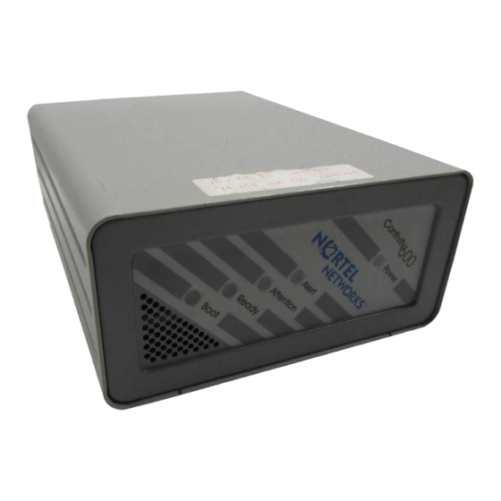
Page 26: Front Panel Leds
26 Chapter 2 Cabling the gateway and turning the power on Front panel LEDs The front panel of the Contivity 600 has five LEDs (Figure 3). These LEDs indicate the status of the Contivity 600. Figure 3 Front panel LEDs... -
Page 27: Leds On The System 10/100Base Ethernet Ports
Chapter 2 Cabling the gateway and turning the power on 27 LEDs on the system 10/100BASE Ethernet ports Figure 4 shows the LEDs for the 10/100BASE Ethernet ports located on the rear of the Contivity 600. Figure 4 LEDs on the system 10/100BASE Ethernet port Green Yellow... -
Page 28: 10/100Base Ethernet Interface Card Leds
28 Chapter 2 Cabling the gateway and turning the power on 10/100BASE Ethernet interface card LEDs Figure 5 shows the LEDs on the 10/100BASE Ethernet interface card. Figure 5 LEDs on the 10/100BASE Ethernet interface card Activity/Link 10/100 Mb/s CS260009A Table 6 describes the LEDs on the 10/100BASE Ethernet interface card. -
Page 29: Adsl Wan Interface Card Leds
ADSL network. Steady green The ADSL interface card has established a link with the ADSL network. Steady green Flashing green The ADSL interface card is sending or receiving network data. (The LED may be dim.) Installing the Contivity 600... -
Page 30: T1/E1 Csu/Dsu Wan Interface Card Leds
30 Chapter 2 Cabling the gateway and turning the power on T1/E1 CSU/DSU WAN interface card LEDs Figure 7 shows the LEDs on the T1/E1 CSU/DSU WAN interface card. Figure 7 LEDs on the T1/E1 CSU/DSU WAN interface card LED 1, Red LED 2, Blue LED 4, Green LED 3, Yellow... -
Page 31: Single V.35/X.21 Wan Interface Card Leds
The signals CDC and DSR are on between the DSU and the adapter. LED 2 detects receive link status. LED 3 Green Power to the adapter is on and the onboard microcode is loaded. LED 4 Green Cable is detected. Installing the Contivity 600... - Page 32 32 Chapter 2 Cabling the gateway and turning the power on 311862-C Rev 00...
-
Page 33: Configuring The Management Ip Interface
Configuring the management IP interface This chapter describes how to configure a management IP address, subnet mask, and default gateway address on a newly installed Contivity 600. After you complete the procedures in this chapter, you will be able to configure and manage the Contivity 600 using a Web browser from a PC. -
Page 34: Required Information
IP address for the management interface The management IP address must be accessible from one of the private physical interfaces on the Contivity 600. For example, if you plan to assign IP address 10.2.3.3 with subnet mask 255.255.0.0 to the private physical interface, the management IP address must reside in the 10.2 network. -
Page 35: Running The Ip Address Configuration Utility
Chapter 3 Configuring the management IP interface 35 • Located on the same subnet as the Contivity 600 to be configured • Operational network connection • CD-ROM drive To test the TCP/IP stack, send a ping command to any host. -
Page 36: Figure 10 Ip Address Configuration Utility Dialog Box
“Testing the configuration” on page 41 to verify that you can access the Contivity 600 from a Web browser. For detailed information about configuring and managing the Contivity 600, refer to the documentation on the Contivity software CD. 311862-C Rev 00... -
Page 37: Using The Serial Interface
Chapter 3 Configuring the management IP interface 37 Using the serial interface You can use the serial interface to assign the Contivity 600 a management IP address and subnet mask so that you can then use a Web browser for management. - Page 38 38 Chapter 3 Configuring the management IP interface Enter the default user name and password for the administrator. The factory default user name is admin and the default password is setup. The user name and password are case sensitive. Please enter the administrator's user name: admin Please enter the administrator's password: ***** The serial main menu appears.
- Page 39 The subnet mask prompt appears. Old Subnet Mask = 0.0.0.0 New Subnet Mask = At the New Subnet Mask prompt, type the subnet mask for the management IP address and press Enter. The Speed/Duplex prompt appears. Installing the Contivity 600...
- Page 40 13 Go to the next section, “Testing the configuration,” to verify that you can access the Contivity 600 from a Web browser. For detailed information about configuring and managing the Contivity 600, refer to the documentation on the Contivity software CD. 311862-C Rev 00...
-
Page 41: Testing The Configuration
After you assign a management IP address to the Contivity 600, start your Web browser to verify that you can access the gateway from the browser. To manage the Contivity 600 using the GUI, your PC must be running one of the following browsers: •... -
Page 42: Figure 11 Welcome Screen
42 Chapter 3 Configuring the management IP interface Figure 11 Welcome screen 311862-C Rev 00... -
Page 43: Troubleshooting
Check the physical connections on the Contivity 600, especially the LAN cable and the power cord. If you still cannot connect to the Contivity 600 using a browser, connect a terminal or PC to the gateway with the serial cable and check the management IP address listed in the serial menu (see “Using the serial interface”... - Page 44 44 Chapter 3 Configuring the management IP interface 311862-C Rev 00...
-
Page 45: Installing Option Cards And Dimms
(FRUs) in the Contivity 600: • LAN, WAN, and serial interface cards • Dual inline memory module (DIMM) To install an interface card or DIMM, you must remove the Contivity 600 chassis from its steel enclosure. This chapter contains the following topics: Topic Page... -
Page 46: Shutting Down The System To Add Or Replace Hardware
46 Chapter 4 Installing option cards and DIMMs Shutting down the system to add or replace hardware Shut down the Contivity 600 and unplug it to install or replace an option card or to replace the DIMM. To shut down the Contivity 600: Use the Web GUI or the command line interface to shut down the gateway. -
Page 47: Figure 12 Removing The Screws From The Bottom Of The Contivity 600
Chapter 4 Installing option cards and DIMMs 47 Turn the Contivity 600 over to see the bottom of the gateway. Using a Phillips screwdriver, remove the 4 screws that secure the bottom to the chassis (Figure 12). Figure 12 Removing the screws from the bottom of the Contivity 600... -
Page 48: Figure 13 Removing The Chassis From The Steel Enclosure
-1 2 V -0 .1 + 5 V -1 0 7 5 W M CS60004A The system board is now exposed. Figure 14 shows the location of the option card slot and the DIMM slot on the Contivity 600 system board. 311862-C Rev 00... -
Page 49: Figure 14 Contivity 600 System Board
Chapter 4 Installing option cards and DIMMs 49 Figure 14 Contivity 600 system board Option card slot DIMM slot CS60005A Warning: Beware of danger if the battery is incorrectly replaced. Replace with the same or an equivalent battery only, as recommended by the manufacturer’s instructions. -
Page 50: Installing And Replacing An Option Card
Figure 14 on page 49). This section provides instructions on installing a LAN, WAN, or serial option card in the Contivity 600 or, if necessary, replacing the installed card. You can install the following option cards in the Contivity 600: •... -
Page 51: Figure 15 Removing The Blank Bracket From The Option Card Slot
Figure 15 Removing the blank bracket from the option card slot Option card slot Blank PCI bracket Phillips screwdriver Screwdriver slot Motherboard CS60010A Slide the option card into the option card slot (Figure 16). Note: Be careful not to bend the copper fingers in the slot. Installing the Contivity 600... -
Page 52: Figure 16 Inserting The Option Card
52 Chapter 4 Installing option cards and DIMMs Figure 16 Inserting the option card Option card slot Option card Motherboard CS60006A Make sure that the option card is seated firmly and evenly in the card slot and that the left tabbed end of the card is seated in its slot. If the card is not seated properly, it will not work. -
Page 53: Figure 17 Securing The Option Card In The Slot
C O N S O L A N 1 L A N 0 D C IN P + 1 2 V -1 .7 A -1 2 V -0 .1 + 5 V -1 0 7 5 W M CS60009A Installing the Contivity 600... -
Page 54: Replacing A Dimm
10 Reconnect the power cord to restart the Contivity 600. Replacing a DIMM The Contivity 600 has one slot for a dual inline memory module (DIMM). If you have a Contivity 600 with a 64 MB DIMM, you can upgrade system memory by replacing the installed DIMM with a 128 MB DIMM. -
Page 55: Figure 19 Installing A Dimm
53). 10 Replace the 4 Phillips screws that secure the bottom panel to the chassis (see Figure 12 on page 47). 11 Reconnect the network cables. 12 Reconnect the power cord to restart the Contivity 600. Installing the Contivity 600... - Page 56 56 Chapter 4 Installing option cards and DIMMs 311862-C Rev 00...
-
Page 57: Chapter 5 Using Recovery Mode
Chapter 5 Using recovery mode The Contivity 600 does not have a floppy disk drive, so the software image is built into the onboard flash operating system. Recovery mode on the Contivity 600 is also built into the flash operating system. You use recovery mode to restore software to a Contivity 600. - Page 58 Web interface. Note: The switch marked FD is reserved for future use. Pressing this switch has no effect. From the Web browser, enter the management IP address of the Contivity 600. The Recovery Diskette screen appears (Figure 20). From this screen, you can perform the following tasks: •...
-
Page 59: Figure 20 Recovery Diskette Screen
Chapter 5 Using recovery mode 59 Figure 20 Recovery Diskette screen Installing the Contivity 600... - Page 60 • Restore the factory default configuration by selecting Restore Factory Configuration, then clicking Restore to return the Contivity 600 to its original factory default configuration. This erases data contained in flash memory and also in the configuration file.
- Page 61 • Alternatively, you can restore a new factory default software image and file system to the Contivity 600 hard disk. Specify the name or address and path of the network file server onto which the software from the Nortel Networks CD has been installed.
- Page 62 62 Chapter 5 Using recovery mode 311862-C Rev 00...
-
Page 63: Technical Specifications
Appendix A Technical specifications This appendix provides technical specifications for the Contivity 600 chassis and its interfaces. Chassis specifications Table 10 lists physical, electrical, and environmental specifications for the chassis. Table 10 Physical, electrical, and environmental specifications Specification Description Physical Height 4 in. -
Page 64: System Ports
64 Appendix A Technical specifications System ports The Contivity 600 system board provides the following built-in interfaces: • 10/100BASE Ethernet LAN ports • Serial port This section provides information about the 10/100BASE Ethernet LAN ports and the serial port on the system board. -
Page 65: Serial Port
Chapter 3, “Configuring the management IP interface,” on page 33). The serial cable provided with the Contivity 600 is a DB9/DB25-to-DB9/DB25 cable. This cable provides a crossover connection (transmit-to-receive and receive-to-transmit). The DB9 connector goes into the gateway and the other DB9 or DB25 connector goes into your workstation. -
Page 66: Modem Cable Specifications
66 Appendix A Technical specifications Modem cable specifications If you need to connect a modem to a Contivity 600, you must obtain an appropriate modem cable. The modem cable must have a 9-pin D-sub plug that connects to the Contivity 600 serial port and a 25-pin D-sub plug that connects to... -
Page 67: Hardware Option Cards
Appendix A Technical specifications 67 Hardware option cards The Contivity 600 provides one PCI slot that supports the following option cards: • 10/100BASE Ethernet interface card • ADSL WAN interface card • ISDN BRI S/T or U interface card •... -
Page 68: Adsl Wan Interface Card
68 Appendix A Technical specifications ADSL WAN interface card The ADSL Annex A and Annex B WAN interface cards have a single RJ-11 connector that provides the signals needed to interface to the digital subscriber line access multiplexer (DSLAM) and to telephone equipment. Figure 24 shows the ADSL WAN interface card. -
Page 69: Isdn Bri Interface Card
The connector on the ISDN BRI S/T and ISDN BRI U interface cards accommodates an 8-pin RJ-45 modular patch cord. These cables are commonly sold as Category 5, or Ethernet, cables. Note: Nortel Networks does not supply a cable with the ISDN BRI interface cards. Installing the Contivity 600... -
Page 70: Table 15 Isdn Bri S/T Cable Pinouts
70 Appendix A Technical specifications Table 15 provides the ISDN BRI S/T cable pinouts. Table 15 ISDN BRI S/T cable pinouts Function Receive + Transmit + Transmit - Receive - Table 16 provides the ISDN BRI U cable pinouts. Table 16 ISDN BRI U cable pinouts Function U interface network connection (tip) U interface network connection (ring) -
Page 71: T1/E1 Csu/Dsu Wan Interface Card
8-pin RJ-48 modular patch cord. These cables are commonly sold as Category 5, or Ethernet, cables. Note: Nortel Networks does not supply the T1/E1 CSU/DSU WAN interface cable with the WAN interface card. The cable you use should be wired in accordance with EIA-568-A wiring style. -
Page 72: Table 17 T1/E1 Csu/Dsu Cable Pinouts For Crossover Connection
T1/E1 CSU/DSU will not work to specifications. Data may be corrupted. Table 18 provides the T1/E1 CSU/DSU cable pinouts for a straight-through connection. Table 18 T1/E1 CSU/DSU cable pinouts for straight-through connection Nortel Networks termination Remote termination Signal Pin # to Pin # Signal... -
Page 73: Single V.35/X.21 Wan Interface Card
1B RXDA pair 2A RXDB pair 2B TXCA pair 3A TXCB pair 3B RXCA pair 4A RXCB pair 4B SCTEA pair 5A SCTEB pair 5B RTSA pair 6A RTSB pair 6B no conn Note 1 Installing the Contivity 600... - Page 74 74 Appendix A Technical specifications Table 19 V.35 cable pinouts (continued) Standard-wired Pair number Special-wired end 28-pin male Signal name and conductor end 34-pin male Notes CTSA pair 7A CTSB pair 7B no conn Note 1 DSRA pair 8A DSRB pair 8B DTRA pair 9A...
-
Page 75: Table 20 X.21 Cable Pinouts
11A no conn Note 2 pair 11B no conn Note 2 pair 12A no conn Note 2 pair 12B no conn Note 2 pair 13A no conn Note 2 M2<-SIGNAL GROUND pair 13B Note 3 Installing the Contivity 600... -
Page 76: V.90 Modem Interface Card
76 Appendix A Technical specifications Table 20 X.21 cable pinouts (continued) Standard-wired Pair number Standard-wired end 28-pin male Signal name and conductor end 15-pin male Notes SHIELD pair 14A Note 4,5 SIGNAL GROUND pair 14B Note 3,5 The following notes apply to the single X.21 cable: 1. -
Page 77: Index
Index Numbers 10/100BASE Ethernet interface card cable, modem 66 cable specifications 64 cables connector 64 available from Nortel Networks 22 described 67 connecting 24 installing 50 connecting to the gateway 23 LEDs 28 ordering 22 10/100BASE system LAN port power. See AC power cord... - Page 78 ISDN BRI U interface card default gateway, defined 34 cable pinouts 70 connector 69 DIMMs (dual inline memory modules), installing installing 50 Contivity 600 54 LAN interface cards electrical specifications 63 connector 64 environmental specifications 63 LEDs 28 specifications 67...
- Page 79 V.35 pinouts 73 modem cable 66 X.21 pinouts 75 serial interface cable 65 single V.35 WAN interface 73 single V.35/X.21 WAN interface card, single X.21 WAN interface 75 installing 50 T1/E1 CSU/DSU WAN interface 72 site requirements 20 Installing the Contivity 600...
- Page 80 67 installing 50 serial port 65 LEDs system ports 64 ADSL 29 subnet mask, defined 34 single V.35/X.21 31 support, Nortel Networks 16 T1/E1 CSU/DSU 30 system LAN port specifications cable specifications 64 ADSL 68 connector 64 single V.35/X.21 73...