Table of Contents
Advertisement
Quick Links
Advertisement
Table of Contents

Related Manuals for Omron SPINOGY 3G3MX2


Summary of Contents for Omron SPINOGY 3G3MX2
- Page 1 Quick Start Guide 3G3MX2...
- Page 2 spinogy.de...
-
Page 3: Table Of Contents
Index General remarks 01.1 Notice 01.2 Limitaton of liability 01.3 Product name 01.4 Labeling of the frequency inverter MX2 Technical description 02.1 Product overview 02.2 Technical data 02.3 Construction of the 3G3MX2 Installation 03.1 Assembly of the 3G3MX2 03.2 Installation/ removal method of the terminal block cover 03.3 Wiring of 3G3MX2 03.4... -
Page 4: General Remarks
Labeling of the frequency inverter MX2 The Omron MX2 inverters are equipped with product labels on the right side of the housing, as pictured below. It must be ensured that the technical data on the label is compatible to the network supply and the safety requirements of the application. -
Page 5: Technical Description
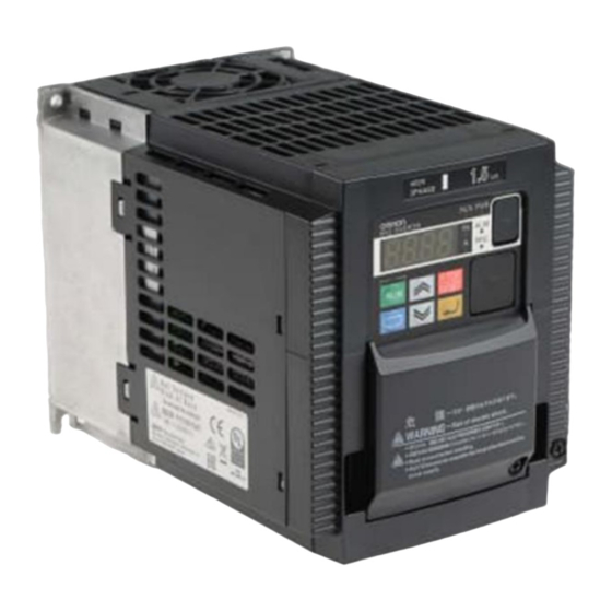
Technical description 02.1 Product overview Input Type ND-mode HD-Mode Rated Motor output Rated Motor output current (A) (kW) current (A) (kW) MX2-AB007 0,75 1 x 230 V MX2-AB015 MX2-AB022 12,0 11,0 MX2-A4004 0,75 MX2-A4007 0,75 MX2-A4015 MX2-A4022 3 x 400 V MX2-A4030 MX2-A4040 11,1... -
Page 6: Construction Of The 3G3Mx2
changeable by a short bar 68 functions assignable Intelligent output terminal 48 functions assignable Output signal Monitor output (analog) Pulse train output (0~10 Vdc, 32 kHz max.) Alarm output contact ON for inverter alarm (1c contacts, both normally open or closed available.) Temperature Operating (ambient): -10 to 50°C / Storage: -20 to 65°C... - Page 7 The following figure shows the designation of the parts inside the terminal block cover. Name Description Modbus-RTU Use this Terminal Resistor selector switch for RS-485 terminals on the control Termination resistor circuit terminal selector switch block. When this switch is turned ON, the internal 200 Resistor is connected. Safety function selector Turn this switch ON when using the safety function.
-
Page 8: Installation
Installation 03.1 Mounting of the 3G3MX2 The frequency inverter is intended for vertical wall mounting. The frequency inverter must be installed on a wall surface made of non-flammable material (e.g. metal). The following mounting distances to other components must be observed to ensure sufficient ventilation. 03 Installation... -
Page 9: Installation/Removal Method Of The Terminal Block Cover
03.2 Installation/removal method of the terminal block cover Disassemble the terminal block cover in the following steps: 1. Loosen the screw(s) securing the terminal block cover. 2. Press the terminal block cover in the direction of the arrow and lift it down to remove it. 03.3 Wiring of the 3G3MX2 Power connections... - Page 10 Logic control wiring Before wiring the logic controller, a power-up test must be performed (see chapter 04 Commissioning). 03 Installation...
-
Page 11: Wiring Of The Spinogy X22 To The Mx2
03.4 Wiring of the SPINOGY X22 to the MX2 03 Installation... - Page 12 03 Installation...
-
Page 13: Commissioning
Commissioning 04.1 Power-up test After wiring the frequency inverter and motor, the power-up test follows. The procedure that follows is designed for the first-time use of the drive. Please verify the following conditions before conducting the power-up test: • The inverter is new, and is securely mounted to a non-flammable vertical surface. •... - Page 14 Items Contents (1) POWER LED Turns ON (Green) while the inverter is powered up. (2) ALARM LED Turns ON (Red) when the inverter trips. · Turns ON (Green) when the display shows (3) Programm LED changeable parameter. · Blinks when there is a mismatch in setting. Turns ON (Green) when the inverter is driving the (4) RUN LED motor.
-
Page 15: Function Groups Of The Parameters
04.3 Function groups of the parameters The parameters are divided into individual function groups. The term function applies to both monitoring modes and parameters. These are all accessible through function codes that are primary 4-character codes. The various functions are separated into related groups identifiable by the left-most character, as the table shows. Function group Type (category) of function Mode to access... - Page 16 04 Commissioning...
-
Page 17: Important Parameters
04.5 Important parameters The parameters for operating a SPINOGY spindle can be taken from the corresponding parameter list (available from SPINOGY). This includes a useful selection of the respective parameters. In case one of the parameters should be programmed differently, the following table lists the most important parameters with the respective option possibility. -
Page 18: First Operation Of The Spindle
Parameters for DC-Brake Compared to the normal deceleration to stop, the DC braking function provides additional stopping torque. This setting is recommended by SPINOGY because in case of an emergency stop, the spindle is decelerated faster. Func. code Name Description Three options, select codes: 00... -
Page 19: Troubleshooting
Troubleshooting This chapter gives a brief overview of possible errors and their causes that may occur during operation with the MX2 frequency inverter. For a detailed explanation, refer to OMRON's MX2 Operation Manual. 05.1 Error codes An error code will appear on the display automatically when a fault causes the inverter to trip. An error is represented in the following form. - Page 20 When the BRD operation rate exceeds the setting Braking resistor overload of “b090”, this protective function shuts off protection the inverter output and displays the error code. When the DC bus voltage exceeds a threshold, Over-voltage protection due to regenerative energy from the motor. When the built-in EEPROM memory has problems due to noise or excessive temperature, EEPROM error...
- Page 21 The inverter tests for input over-voltage after the inverter has been in Stop Mode for 100 seconds. Input over-voltage If an over-voltage condition exists, the inverter enters a fault state. After the fault is cleared, the inverter can enter Run Mode again. When the inverter internal temperature is above the threshold, the thermal sensor in the inverter Inverter thermal trip...
- Page 22 When the connection between inverter Operator connection and operator keypad failed, inverter trips and displays the error code. When “trip” is selected (C076=00) as a Modbus communication behavior in case of communication error, error inverter trips when timeout happens. The program stored in inverter memory has Drive Programming invalid been destroyed, or the PRG terminal was instruction...
-
Page 23: Restoring Factory Settings
05.2 Restoring factory settings The MX2 frequency inverter can be reset to the original factory/default settings. To initialize the inverter, follow the steps below. 01. Select initialization mode in b084. 02. If b084 = 02, 03 or 04, select initialization target data in b094. 03. - Page 24 ©SPINOGY GmbH Rev.07/2022 06 Troubleshooting...