Table of Contents
Advertisement
Quick Links
Advertisement
Table of Contents

Related Manuals for Benning DB 1


Summary of Contents for Benning DB 1
- Page 1 Operating manual Demonstration Case BENNING DB 1 part no. 044132...
-
Page 2: Table Of Contents
Demonstration Case DB 1 Table of contents Introduction......................3 Safety instructions....................4 Applicable regulations ..................... 5 Device description ....................5 Measuring / testing................... 6 Operating elements and connections............... 8 Technical data....................9 Maintenance ......................10 Calibration......................10 Scope of delivery ....................10... -
Page 3: Introduction
Demonstration Case DB 1 Introduction The demonstration case BENNING DB1 has been designed in order to be able to present measuring instruments, current clamps and voltage testers as quickly as pos- sible. This operating manual contains information that is necessary for proper operation of the device. -
Page 4: Safety Instructions
Demonstration Case DB 1 Safety instructions The device has been built and tested in accordance with the applicable regulations (see chapter 3) and has left the factory in perfectly safe technical condition. To preserve this condition and to ensure safe operation of the device, the user must observe the instructions and warnings given in this operating manual at all times. -
Page 5: Applicable Regulations
(EMC) Device description For its active output voltages, the BENNING demonstration case requires a mains voltage of 230 V 50 Hz. The device (demonstration case) must be connected to a protected shock-proof socket 230 V by means of the enclosed mains cable. -
Page 6: Measuring / Testing
Demonstration Case DB 1 Measuring / testing Connect the device to the mains. The IEC connector with two fuses and a mains switch is situated at the rear. Connect it to the enclosed mains cable and a shock- proof socket (230 V). The device is immediately ready for operation. - Page 7 Demonstration Case DB 1 Resistance test, Set the function of the multimeter to position resistance / ohms and connect the mea- suring lines (or the DUSPOL tester with continuity test) to the measuring jacks for resistance. Read the measured value or observe the maximum measured value of the DUSPOL voltage tester respectively! The multimeter displays the resistance values in ohms (22 / 1k / 470 k).
-
Page 8: Operating Elements And Connections
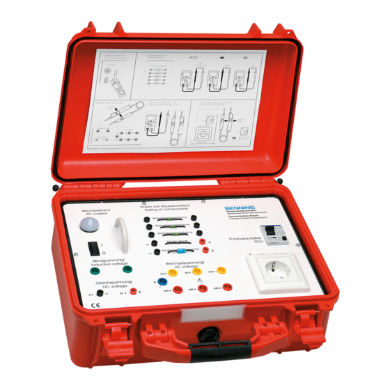
Demonstration Case DB 1 Operating elements and connections Fig. 1 demonstration case without cover Caption for fig. 1: lamp for AC load AC current line AC switch 0 - I pair of jacks, green, reactive voltage pair of jacks, black 0 (-) and red (+) 24 V DC jack, blue, "N"... -
Page 9: Technical Data
Demonstration Case DB 1 Technical data Mains connection: 230 V ± 10 %, 50 - 60 Hz Current consumption: approx. 0.6 A Max. pre-fuse: 16 A Built-in microfuse (F1, F2): T 1 A (250 V, 5x20) Current load of the voltage measuring jacks and the test socket max. -
Page 10: Maintenance
Calibration The device does not require any calibration. Scope of delivery BENNING demonstration case (plastics carrying case) mains cable with shock-proof plug and IEC socket brief operating manual (glued in the device cover) operating manual...