Advertisement
Available languages
Available languages
Quick Links
Bedienungsanleitung
D
Operating manual
Notice d'emploi
F
Návod k obsluze
Gebruiksaanwijzing
Instrukcja obsługi
ST 710
R
PE
R
ISO
ON/OFF
press 2 sec.
Klasse I
Klasse II
Class I
Class II
R
PE
R
R
ISO
ISO
I
I
EA
EA
DIN VDE 0701/0702, BGV A3, ÖVE/ÖNORM E 8701, NEN 3140
Prüfling während der Prüfung einschalten
Switch on test object during test
M
A
m
Leitung
Cord
R
PE
R
ISO
Leitungstest
Wiring
Advertisement

Related Manuals for Benning ST 710


Summary of Contents for Benning ST 710
-
Page 1: Operating Manual
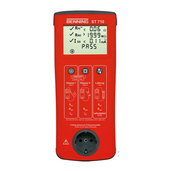
Bedienungsanleitung Operating manual Notice d’emploi Návod k obsluze Gebruiksaanwijzing Instrukcja obsługi ST 710 ON/OFF press 2 sec. Klasse I Klasse II Leitung Class I Class II Cord Leitungstest Wiring DIN VDE 0701/0702, BGV A3, ÖVE/ÖNORM E 8701, NEN 3140 Prüfling während der Prüfung einschalten... - Page 2 Rys. 1: Panel przedni przyrządu Bild 2: Geräteoberseite Fig. 2: Top side of the device Fig. 2: Face supérieure de l'appareil Obr. 2: Horní strana přístroje Fig. 2: Bovenaanzicht apparaat Rys. 2: Górna strona urządzenia BENNING ST 710 01/ 2009...
- Page 3 Switch on test object during test (veiligheidslaagspanning) Rys. 4: Testowanie urządzeń II klasy ochronnej (urządzenia z izolacją ochronną bez kabla ochronnego i z dotykającymi się i przewodzącymi częściami) lub testowanie urządzeń III klasy ochronnej (małe napięcie ochronne) BENNING ST 710 01/ 2009...
- Page 4 2 sec. Klasse I Klasse II Leitung Class I Class II Cord Leitungstest Wiring DIN VDE 0701/0702, BGV A3, ÖVE/ÖNORM E 8701, NEN 3140 Prüfling während der Prüfung einschalten Switch on test object during test BENNING ST 710 01/ 2009...
- Page 5 Prüfling während der Prüfung einschalten Switch on test object during test Bild 7: Batteriewechsel Fig. 7: Battery replacement Fig. 7: Remplacement des piles Obr. 7: Výměna baterií Fig. 7: Vervanging van de batterij. Rys. 7: Wymiana baterii BENNING ST 710 01/ 2009...
- Page 6 Elektrofachkräfte (EF), befähigte Personen und Elektrotechnisch unterwiesene Personen (EuP) Das BENNING ST 710 ist zur Messung in trockener Umgebung vorgesehen. Es darf nicht in Stromkreisen mit einer höheren Nennspannung als 300 V AC eingesetzt werden (näheres hierzu im Abschnitt 6: Umgebungsbedingungen).
- Page 7 Extreme Vorsicht bei Arbeiten um blanke Leiter oder Hauptleitungsträger. Ein Kontakt mit Leitern kann einen Elektroschock verursachen. Das BENNING ST 710 darf nur in Stromkreisen der Überspannungskategorie II mit max. 300 V Leiter gegen Erde benutzt werden. Beachten Sie, dass Arbeiten an spannungsführenden Teilen und Anlagen grundsätzlich gefährlich sind.
- Page 8 Bei Arbeitstemperatur von 31° C bis 40° C: relative Luftfeuchte kleiner 75 %, Lagerungstemperatur: Das BENNING ST 710 kann bei Temperaturen von - 25° C bis + 65° C (Luftfeuchte 0 bis 80 %) gelagert werden. Dabei sind die Batterien aus dem Gerät herauszunehmen.
- Page 9 PE-Verbindung Prüfen mit dem BENNING ST 710 8.1 Vorbereiten der Prüfung Benutzen und lagern Sie das BENNING ST 710 nur bei den angegebenen Lager- und Arbeits- temperaturbedingungen, vermeiden Sie dauernde Sonneneinstrahlung. Angaben von Nennspannung und Nennstrom auf den Sicherheitsmessleitungen überprüfen.
- Page 10 8.1.1 Ein-, Ausschalten des BENNING ST 710 Durch ein gedrückt halten der Tasten 2 + 3 für ca. 3 Sekunden wird das BENNING ST 710 ein- geschaltet, 2 Signaltöne bestätigen dies. Erneutes drücken der Tasten schaltet das Gerät aus. Das BENNING ST 710 schaltet sich nach ca. 3 Minuten selbstständig ab. (APO, Auto-Power- Off).
- Page 11 Symbol im Display erscheint. Bewegen Sie die Anschlussleitung des Prüfobjektes über die komplette Länge um eine Schwachstelle oder einen Bruch in der Schutzleiterbahn festzustellen. Das BENNING ST 710 erfasst fortlaufend den aktuellen Messwert im Display und hinterlegt den Maximalwert im Speicher. Durch erneuten Druck auf die Taste 2 wird die Messung mit vertauschter Polarität durchgeführt.
- Page 12 Schutzklasse III (Schutzkleinspannung) Prüfung von Geräten ohne Schutzleiter und mit berührbaren leitfähigen Teilen. Das Prüfobjekt muss an die Prüfsteckdose 1 des BENNING ST 710 angeschlossen werden. Stellen Sie eine Verbindung zwischen der 4 mm Prüfbuchse 6 und einem Metallteil des Prüfobjekts mittels der Prüfleitung mit Abgreifklemme her.
- Page 13 Symbol im Display erscheint. Bewegen Sie die Anschlussleitung des Prüfobjektes über die komplette Länge um eine Schwachstelle oder einen Bruch in der Schutzleiterbahn festzustellen. Das BENNING ST 710 erfasst fortlaufend den aktuellen Messwert im Display und hinterlegt den Maximalwert im Speicher. Durch erneuten Druck auf die Taste 4 wird die Messung mit vertauschter Polarität durchgeführt.
- Page 14 Fehlern bei Messungen, Erkennbaren Folgen von längerer Lagerung unter unzulässigen Bedingungen und Erkennbaren Folgen von außerordentlicher Transportbeanspruchung. In diesen Fällen ist das BENNING ST 710 sofort abzuschalten, von den Prüfstellen zu entfernen und gegen erneute Nutzung zu sichern. 9.2 Reinigung Reinigen Sie das Gehäuse äußerlich mit einem sauberen und trockenen Tuch (Ausnahme spe-...
- Page 15 Um die angegebenen Genauigkeiten der Messergebnisse zu erhalten, muss das Gerät regel- mäßig durch unseren Werksservice kalibriert werden. Wir empfehlen ein Kalibrierintervall von einem Jahr. Senden Sie hierzu das Gerät an folgende Adresse: Benning Elektrotechnik & Elektronik GmbH & Co. KG Service Center Robert-Bosch-Str. 20 D –...
-
Page 16: Operating Instructions
The BENNING ST 710 is intended for making measurements in dry environment. It must not be used in power circuits with a nominal voltage higher than 300 V AC (More details in Section 6. “Environmental conditions”). - Page 17 3.4 One operating instructions manual Parts subject to wear: The BENNING ST 710 is supplied by six 1.5 V batteries/ type AA (IEC LR6). Note on optional accessories: Leakage current clamp BENNING CM 9 for differential current measurement of single-phase and three-phase loads (044065) Test badges “next test date”, 300 pieces (756213)
- Page 18 6 4 mm test socket, for connecting the test cable with alligator clip 7 IEC connector, for connecting the IEC power cord General information The BENNING ST 710 is intended for electrical safety tests according to DIN VDE 0701/ 0702, BGV A3, ÖVE/ ÖNORM E8701 and NEN 3140. Automatically, the BENNING ST 710 verifies the type of the connected test object and informs the user in case of incorrect selection of the testing procedure [ 2 ...
- Page 19 Do not permanently expose the device to sunlight. Check rated voltage and rated current details specified on the safety measuring lines. Strong sources of interference in the vicinity of the BENNING ST 710 can lead to unstable readings and measuring errors.
- Page 20 Switching the BENNING ST 710 ON/ OFF Press and hold the keys 2 and 3 for approx. 3 seconds to switch the BENNING ST 710 on. 2 acoustic signals confirm that the device is switched on. Press the keys again to switch the device off.
- Page 21 The BENNING ST 710 continuously records the current measured value on the display and stores the maximum value in the memory. By pressing the key 2 again, the measurement is carried out with reversed polarity.
- Page 22 IEC coupler) and for the testing of cable reels, multiple distributors and extension cables. 8.2.3.1 Testing of IEC power cords (IEC adapter cables) Connect the IEC power cord to be tested to the BENNING ST 710 by means of the IEC connector 7 and the test socket 1 .
-
Page 23: Cross Section
The BENNING ST 710 continuously records the current measured value on the display and stores the maximum value in the memory. By pressing the key 4 again, the measurement is carried out with reversed polarity. - Page 24 Electrical danger! Work on the opened BENNING ST 710 under voltage may be carried out only by skilled electricians with special precautions for the prevention of accidents. Make the BENNING ST 710 voltage free as follows before opening the instrument: Switch the tester off.
- Page 25 To maintain the specified precision of the measurement results, the instrument must be recali- brated at regular intervals by our factory service. We recommend a recalibration interval of one year. Send the appliance to the following address: BENNING Elektrotechnik & Elektronik GmbH & Co. KG Service Centre Robert-Bosch-Str. 20 D - 46397 Bocholt 10.
-
Page 26: Notice D'emploi
électrotechnique Le BENNING ST 710 est conçu pour effectuer des mesures dans un environnement sec. Il ne doit pas être utilisé dans des circuits dont la tension nominale est supérieure à 300 V CA (pour de plus amples informations, consulter la section «... - Page 27 3.5 six piles rondes de 1,5 V mignon (IEC LR 6/ AA) montées initialement dans l’appareil, 3.6 une notice d’emploi. Remarque concernant les pièces d’usure : Le BENNING ST 710 est alimenté par six piles rondes incorporées de 1,5 V mignon (IEC LR6/ AA). Remarque concernant les accessoires en option : pince de courant de fuite BENNING CM 9 pour la mesure du courant différentiel sur les...
- Page 28 7 fiche mâle CEI (connecteur CEI), afin de raccorder le câble d'alimentation CEI Indications générales Le contrôleur BENNING ST 710 sert à effectuer des contrôles de sécurité conformément à DIN VDE 0701/ 0702, BGV A3, ÖVE/ ÖNORM E8701 et NEN 3140.
- Page 29 - tension entre le conducteur neutre (N) et le conducteur de terre (PE) 7.6 Valeurs limites selon DIN VDE 0701/ 0702 et ÖVE/ ÖNORM E 8701-1 Remarque: Les valeurs limites préréglées imprimées en gras sont mémorisées dans l'appareil BENNING ST 710. Classe de protection I Classe de...
- Page 30 8.1.1 Mise en marche/ en arrêt du contrôleur BENNING ST 710 L'appareil BENNING ST 710 est allumé en maintenant appuyées les touches 2 et 3 pour 3 secondes environ. La mise en marche est confirmée par 2 signaux acoustiques. Appuyez sur les touches encore une fois afin d'éteindre l'appareil. Après 3 minutes environ, l'appareil BENNING ST 710 s'éteint automatiquement (APO, Auto- Power-Off).
- Page 31 à côté du symbole I , si le courant du conducteur de protection I est inférieur à la valeur limite admissible. Le contrôle est considéré comme réussi, si le symbole « PASS » est affiché sur l'écran. BENNING ST 710 01/ 2009...
- Page 32 Contrôle des appareils sans conducteur de protection et avec des pièces touchables conductrices Raccordez l'objet de contrôle à la prise de test 1 du contrôleur BENNING ST 710. Établissez une connexion entre la douille de test 4 mm 6 et une pièce métallique de l'objet de contrôle au moyen du câble d'essai avec pince crocodile.
- Page 33 8.2.3.1 Contrôle de câbles d'alimentation CEI ( câble d'adaptateur CEI ) Connectez le câble d'alimentation CEI à contrôler à l'appareil BENNING ST 710 au moyen de la fiche mâle CEI 7 et la prise de test 1 . Appuyez sur la touche 4 afin de commencer le contrôle automatique.
-
Page 34: Entretien
Dans ces cas, il faut mettre le BENNING ST 710 immédiatement hors circuit, le retirer du point de mesure et le protéger de manière à ne plus être utilisé. - Page 35 Remplacez les piles de la manière suivante: Éteignez l'appareil BENNING ST 710. Posez l'appareil BENNING ST 710 sur la face avant et dévissez la vis du couvercle du compartiment à piles. Soulevez le couvercle du compartiment à piles (au niveau des cavités du boîtier) de la partie inférieure de l'appareil.
-
Page 36: Návod K Obsluze
10. Ochrana životního prostředí Pokyny pro uživatele Tento návod je určen pro - odborní elektrikáři (EF), oprávněné osoby a - elektrotechnicky poučené osoby (EuP) BENNING ST 710 je určen pro měření v suchém prostředí. Nesmí být použit v obvodech s jme- novitým napětím vyšším než 300 V AC (Blíže v kapitole 6. „Podmínky prostředí“). V návodu k obsluze a na přístroji BENNING ST 710 jsou použity následující symboly: Je dovoleno přiložit NEBEZPEČNĚ AKTIVNÍ vodiče nebo je odstranit. Tento symbol upozorňuje na nebezpečí úrazu elektrickým proudem. Tento symbol upozorňuje na nebezpečí při používání přístroje BENNING ST 710 (řiďte se technickou dokumentací!). Tento symbol na měřicím přístroji BENNING ST 710 znamená, že je přístroj opatřen ochrannou izolací (ochrana třídy II). Tento symbol na BENNING ST 710 znamená, že BENNING ST 710 splňuje směrnice Tento symbol se objeví na displeji, když je vybitá baterie. (AC) Střídavé napětí nebo proud. Uzemnění (napětí vůči zemi). BENNING ST 710... - Page 37 Pozor při pracích v blízkosti holých vodičů nebo nosičů hlavního vedení. Kontakt s vodiči může způsobit úder elektrickým proudem. BENNING ST 710 může být použit jen v obvodech kategorie II s max. 300 V AC proti zemi. Dbejte na to, že práce na vodivých dílech a zařízeních jsou nebezpečné. Napětí...
- Page 38 Význam IP 40: Ochrana proti malým cizím předmětům, proti dotyku nářadím, drátem a podobně s průměrem > 1 mm, (4 - první číslice). Žádná ochrana před vodou, (0 - druhá číslice). EMC: EN 61326-1 - Pracovní teplota a relativní vlhkost: Při teplotě od 0 °C do 30 °C: relativní vlhkost menší 80 %, Při teplotě od 31 °C do 40 °C: relativní vlhkost menší 75 %, - Skladovací teploty: BENNING ST 710 může být skladován při teplotách od - 25 °C do + 65 °C (vlhkost 0 až 80 %). Baterie musí být vyňaty. Elektrické údaje Poznámka: Přesnost měření se udává jako součet relativního podílu měřené hodnoty a počtu číslic (t.j. zobrazení čísla na posledních místech). Přesnost měření platí při teplotách od 18 °C do 28 °C a při relativní vlhkosti menší než 80 %.
- Page 39 8.1 Příprava měření BENNING ST 710 používejte a skladujte výhradně při předepsaných provozních a skladovacích teplotách; přístroj dlouhodobě nevystavujte slunečnímu záření. Zkontrolujte bezpečnou hodnotu jmenovitého napětí a jmenovitého proudu na měřených kabelech. Všechny zdroje rušení v blízkosti BENNING ST 710 vedou k nestabilním hodnotám a chybám měření. Před uvedením do provozu zkontrolujte nepoškozenost přístroje, vedení a zkoušeného zařízení.
- Page 40 Postup zkoušky BENNING ST 710 provádí elektrické bezpečnostní zkoušky podle DIN VDE 0701/ 0702. Podrob- né informace o zkouškách a mezních hodnotách jsou uvedeny v aktuálním vydání norem. BENNING ST 710 samostatně zkontroluje druh připojeného zkušebního zařízení a upozorní uživatele při nesprávném postupu zkoušky [ 2 ... 4 ]. 8.2 Zkoušení elektrických zařízení / provozních prostředků podle DIN VDE 0701/ 0702 Před začátkem zkoušky je nutno provést vizuální kontrolu zkoušeného zařízení...
- Page 41 Zkoušení zařízení třídy ochrany II (s ochrannou izolací) a zařízení třídy ochrany III (bezpečné malé napětí) - Zkoušení zařízení bez ochranného vodiče a s vodivými díly nechráněnými proti doteku. - Zkoušené zařízení musí být připojené na zkušební zásuvku 1 přístroje BENNING ST 710. - Pomocí zkušebního kabelu s připojovací svorkou propojte 4 mm zkušební zdířku 6 a kovový díl zkoušeného zařízení. - Zapněte zkoušené zařízení.
- Page 42 - Stiskem tlačítka 4 se spustí automatický průběh zkoušky. - Zkouška začíná měřením odporu ochranného vodiče R Při překročení nebo nedosažení mezní hodnoty se vedle symbolu R zobrazí nebo Odpor ochranného vodiče je závislý na délce a průřezu zkoušeného kabelu. Je možné, že výsledek měření je přijatelný, ačkoli na přístroji BENNING ST 710 je vedle R zobrazeno Typické hodnoty odporu vedení jsou uvedeny v tabulce 1. Průřez Délka 1,0 mm²...
- Page 43 PE vodiče! viz obr. 6: Měření napětí na externí zásuvce s ochranným kontaktem Údržba Před otevřením BENNING ST 710 odpojte od napětí! Nebezpečí úrazu elektrickým proudem! Práce na otevřeném BENNING ST 710 pod napětím jsou vyhrazeny odborníkům, kteří přitom musí dbát zvýšené opatrnosti. BENNING ST 710 01/ 2009...
- Page 44 Oddělte BENNING ST 710 od napětí, než přístroj otevřete: Vypněte zkušební přístroj Od přístroje odpojte všechny připojovací kabely 9.1 Zajištění přístroje Za určitých podmínek nemůže být bezpečnost při používání BENNING ST 710 zajištěna, například při: zřejmém poškození krytu přístroje, chybách při měření, zřejmých následcích delšího chybného skladování a zřejmých následcích špatného transportu. V těchto případech BENNING ST 710 ihned vypněte, odpojte od měřených bodů a zajistěte, aby přístroj nemohl být znovu použit jinou osobou. 9.2 Čištění Kryt přístroje čistěte opatrně čistým a suchým hadříkem (výjimku tvoří speciální čistící ubrousky). Nepoužívejte žádná rozpouštědla ani čistící prostředky. Zejména dbejte toho, aby místo pro baterie ani bateriové kontakty nebyly znečištěny vyteklým elektrolytem.
- Page 45 Deze gebruiksaanwijzing is bedoeld voor elektriciens, bekwame personen en elektrotechnisch opgeleide personen De BENNING ST 710 is bedoeld voor metingen in droge ruimtes en mag niet worden gebruikt in elektrische circuits met een nominale spanning hoger dan 300 V AC (zie ook pt. 6: ‘Gebruiks- omstandigheden’). In de gebruiksaanwijzing en op de BENNING ST 710 worden de volgende symbolen gebruikt: Aanleggen om GEVAARLIJKE ACTIEVE geleider of demonteren van deze is toe- gestaan.
- Page 46 3.6 Eén gebruiksaanwijzing Opmerking t.a.v. aan slijtage onderhevige onderdelen: De BENNING ST 710 wordt gevoed door zes batterijen van 1,5 V (IEC LR6/ AA, mignon) Opmerking t.a.v. aan optionele toebehor: Lekstroomtang BENNING CM 9 voor verschilstroommeting van één- en driefase verbruikers (044065) Testetiketten „Nächster Prüftermin“, 300 stuks (756213)
- Page 47 Gebruiksomstandigheden De BENNING St 710 is bedoeld om gebruikt te worden voor metingen in droge ruimtes. Barometrische hoogte bij metingen: 2000 m. maximaal. - Categorie van overbelasting/installatie: IEC 61010-1 → 300 V categorie II. Beschermingsgraad stofindringing: 2 Beschermingsgraad: IP 40 (DIN VDE 0470-1 IEC/ EN 60529), Betekenis IP 40: Het eerste cijfer (4);...
- Page 48 - spanning tussen buitengeleider (L) en aardegeleider (PE) - spanning tussen nulgeleider (N) en aardegeleider (PE) 7.6 Grenswaarden volgens NEN 3140, DIN VDE 0701/ 0702 resp. ÖVE/ ÖNORM E 8701-1 Opmerking Vooringestelde grenswaarden (vetgedrukt) zijn in de BENNING ST 710 opgeslagen. Beschermklasse I Beschermklasse Leidingtest...
- Page 49 8.1.1 In- en uitschakelen van de BENNING ST 710 Door de knoppen 2 en 3 ca. 3 seconden ingedrukt te houden, wordt de BENNING ST 710 ingeschakeld. Dit wordt bevestigd door 2 geluidssignalen. Door deze knoppen nogmaals in te drukken, wordt het apparaat uitgeschakeld.
- Page 50 Indien de isolatieweerstand R groter is dan de toelaatbare grenswaarde, verschijnt een naast het R -symbool. Er verschijnt eveneens een naast het I -symbool, indien de aardegeleidersstroom I kleiner is dan de toelaatbare grenswaarde. - De test is succesvol afgesloten, als de melding ‘PASS’ op het display verschijnt. BENNING ST 710 01/ 2009...
- Page 51 III (veiligheidslaagspanning) Testen van apparaten zonder aardegeleider en met aanraakbare geleidende onderdelen. Het testobject moet op het testcontact 1 van de BENNING ST 710 worden aangesloten. Breng door middel van de testleiding met krokodilklem een verbinding tussen het 4mm- testcontact 6 en een metalen deel van het testobject tot stand.
- Page 52 De BENNING ST 710 registreert doorlopend de actuele meetwaarde op het display en bewaart de maximale waarde in zijn geheugen. Door nogmaals op de knop 4 te drukken, wordt de meting met omgekeerde polariteit uitge- voerd.
- Page 53 Gevaarlijke spanning! De BENNING ST 710 wordt gevoed door zes batterijen van 1,5 V (IEC LR6/ AA/ mignon). Als het batterijsymbool op het display 5 verschijnt, moeten de batterijen worden vervangen. Bij het inschakelen van de BENNING ST 710 vindt een batterijtest plaats.
- Page 54 Leg de BENNING ST 710 op zijn voorzijde en draai de schroef uit het batterijdeksel. Open het batterijdeksel (hiervoor bevinden zich uitsparingen in het apparaat). Neem de lege batterijen uit het batterijvak. Leg vervolgens nieuwe batterijen in het batterijvak (let op de correcte polariteit!).
-
Page 55: Instrukcja Obsługi
Niniejszy symbol znajdujący się na przyrządzie BENNING ST 710 oznacza, że przyrząd posiada pełną izolację ochronną (klasa ochronności II). Ten symbol na urządzeniu BENNING ST 710 oznacza, że jest ono zgodne z dyrektywami UE. Niniejszy symbol pojawia się na wyświetlaczu w celu wskazania rozładowania baterii. - Page 56 3.5 Sześć baterie 1,5 V typu mignon (IEC LR6/ AA) zamontowane w przyrządzie jako oryginalne wyposażenie 3.6 Instrukcja obsługi Części podlegające zużyciu: Miernik BENNING ST 710 zasilany jest z sześć baterii 1,5 V typu mignon (IEC LR6/ AA). Wskazówka odnośnie osprzętu do wyboru: Kleszcze prądu upływowego BENNING CM 9 do pomiaru prądu różnicowego do jedno i trójfazowego urządzenia odbiorczego (044065) Plakietka testowania „Termin następnego testu“, 300 sztuk (756213) Łącznik pomiarowy wtyczka z uziemieniem - łącznik wtykowy do pomiaru prądu dyferencjacyjnego, prądu kabla ochronnego i prądu obciążenia do jednofazowych urządzeń odbiorczych, kabel jest wyprowadzony oddzielnie (044131)
- Page 57 BENNING ST 710 samodzielnie sprawdza rodzaj podłączonego testowanego przedmiotu i daje użytkownikowi wskazówkę w wypadku niewłaściwego wyboru przebiegu sprawdzania [ 2 ... 4 ]: Wstępnie nastawione wartości graniczne i wyniki badania z dobrą/złą wypowiedzią ułatwiają ocenę badania. Warunki środowiskowe: - Przyrząd BENNING ST 710 przeznaczony jest do wykonywania pomiarów w środowisku suchym. - Maksymalna wysokość nad poziomem morza dla wykonywanych pomiarów: 2000 m, - Kategoria przepięciowa/ Kategoria lokalizacji: IEC 61010-1 → 300 V kategoria II Klasa zanieczyszczenia: 2, - Stopień ochrony obudowy: IP 40.
- Page 58 Wskazanie: - Napięcie pomiędzy kablem zewnętrznym (L) a kablem obojętnym (N) - Napięcie pomiędzy kablem zewnętrznym (L) a kablem uziemiającym PE) - Napięcie pomiędzy kablem obojętnym (N) a kablem uziemiającym (PE) 7.6 Wartości graniczne DIN VDE 0701/ 0702 Wskazówka: Wstępnie nastawione wartości graniczne pogrubionym pismem są zapisane w pamięci BENNING ST 710. Klasa ochrony I Klasa ochrony II, III test kabla dla kabli z prądem po- miarowym ≤ 16 A: ≤ 0,3 Ω do 5 m długości, ≤ 0,3 Ω...
- Page 59 - Sprawdzić bezpieczną wartość napięcia znamionowego i prądu znamionowego na testowanych kablach - Wszystkie źródła zakłóceń znajdujące się w pobliżu BENNING ST 710 są przyczyną niestabilnych wartości i błędów przy pomiarach. Przed każdym uruchomieniem należy sprawdzić, czy urządzenie, kable i testowany przedmiot nie są uszkodzone.
- Page 60 - Nciskając przycisk 2 zostanie kontynuowany przebieg testowania przy zbyt małym obciążeniu (R < 100 kΩ). - Jeśli opór izolacji R jest większy od dopuszczalnej wartości granicznej, obok symbolu R pojawi się - Również obok symbolu I pojawi się , jeśli prąd kabla ochronnego I jest mniejszy aniżeli dopuszczalna wartość graniczna. - Test zostanie zakończony wtedy, gdy na wyświetlaczu pojawi się symbol „PASS“. BENNING ST 710 01/ 2009...
- Page 61 . Poruszyć kabel przyłączeniowy testowanego przedmiotu wzdłuż całej długości w celu ustalenia słabego miejsca lub pęknięcia w torze kabla ochronnego. BENNING ST 710 zapisuje stopniowo aktualną wartość pomiaru na wyświetlaczu i zapisuje w pamięci wartość maksymalną. Ponowne naciśnięcie przycisku 2 spowoduje wykonanie testu z zamienioną biegunowością.
- Page 62 . Poruszyć kabel przyłączeniowy testowanego przedmiotu wzdłuż całej długości w celu ustalenia słabego miejsca lub pęknięcia w torze kabla ochronnego. BENNING ST 710 zapisuje stopniowo aktualną wartość pomiaru na wyświetlaczu i zapisuje w pamięci wartość maksymalną. Ponowne naciśnięcie przycisku 4 spowoduje wykonanie testu z zamienioną biegunowością.
- Page 63 PE! Patrz Rysunek 6: P omiar napięcia na zewnętrznym gniazdku wtykowym z zestykiem ochron- Konserwacja Przed otwarciem przyrządu BENNING ST 710, należy upewnić się, że nie znajduje się on pod napięciem. Niebezpieczeństwo porażenia prądem elektrycznym! Praca pod napięciem na otwartym przyrządzie BENNING ST 710 może być prowadzona wyłącznie przez uprawnionego elektryka z zastosowaniem środków zapobiegającym...
- Page 64 9.3 Wymiana baterii Przed otwarciem przyrządu BENNING ST 710, należy upewnić się, że nie znajduje się on pod napięciem. Niebezpieczeństwo porażenia prądem elektrycznym! Przyrząd BENNING ST 710 zasilany jest przez sześć baterie miniaturowe 1,5 V Mignon (AA/ IEC LR6). Jeżeli na wyświetlaczu pojawi się symbol baterii 5 , wówczas konieczna jest wymiana baterii (patrz rysunek 7).
- Page 65 Benning Elektrotechnik & Elektronik GmbH & Co. KG Münsterstraße 135 - 137 D - 46397 Bocholt Phone: +49 (0) 2871 - 93 - 0 • Fax: +49 (0) 2871 - 93 - 429 www.benning.de • E-Mail: duspol@benning.de...