Table of Contents
Advertisement
Quick Links
Advertisement
Table of Contents

Related Manuals for Benning MM 7-2


Summary of Contents for Benning MM 7-2
- Page 1 Operating manual Translation of the German original version...
- Page 2 General non-discrimination Benning is aware of the importance of language with regard to the gender equality and endeavors to take this into account at all times. To improve readability, we have refrained from consistently using differentiating formulations.
-
Page 3: Table Of Contents
Diode test .......................... 29 4.3.6 Capacitance ranges ...................... 30 4.3.7 Frequency ranges ....................... 30 4.3.8 Temperature ranges...................... 31 Operation.............................. 32 Requirements for tests and measurements ................ 32 Connecting the safety measuring lines ................ 33 Voltage, frequency or duty cycle measurement .............. 34 5235 / 05/2022 en BENNING MM 7-2... - Page 4 Maintenance ............................. 42 Maintenance schedule ...................... 42 Making the device free of voltage .................. 42 Cleaning the device...................... 43 Replacing the batteries ....................... 44 Calibrating the device...................... 44 Replacing the fuses...................... 45 Technical data............................ 46 Disposal and environmental protection .................... 47 Index ................................. 48 BENNING MM 7-2 5235 / 05/2022 en...
- Page 5 BENNING TA 2 ..........................Figure 4 BENNING TA 3 ..........................Figure 5 Ø 4 mm measuring lines with 2 mm measuring probe ..............Figure 6 BENNING MM 7-2 device structure ..................... Figure 7 Rotary switch ..........................Figure 8 Digital display..........................Figure 9 Voltage, frequency or duty cycle measurement................
- Page 6 Mains frequency ranges (Hz)....................... Table 19 5 V logic-level frequency ranges (Hz) ..................Table 20 Logic-level duty cycle (%) ......................Table 21 Temperature ranges (°C / °F) ...................... Table 22 Maintenance schedule ......................... Table 23 Technical data ..........................BENNING MM 7-2 5235 / 05/2022 en...
-
Page 7: Introduction
1.1 General notes Introduction The TRUE RMS digital multimeter BENNING MM 7‑2 described here (in the following only referred to as “device”) is intended for testing in electric circuits with a nominal voltage up to a maximum of 1 000 V‑AC or 1 000 V‑DC. The device enables you to perform the following tests and measurements: •... -
Page 8: History
Information in this operating manual can be changed at any time without prior notice. Benning is not obligated to make amendments to this operating manual or to keep it up to date. -
Page 9: Service & Support
Phone: +49 2871 93-555 Fax: +49 2871 93‑6555 E-Mail: helpdesk@benning.de Internet: www.benning.de Returns management Easily and conveniently use the BENNING returns portal for a quick and smooth returns processing: https://www.benning.de/service-de/retourenabwicklung.html Phone: +49 2871 93-554 E-Mail: returns@benning.de Return address BENNING Elektrotechnik und Elektronik GmbH & Co. KG Retourenmanagement Robert-Bosch-Str. -
Page 10: Safety
The device has been built and tested in compliance with the following standards and has left the factory in perfectly safe condition. • IEC / DIN EN 61010-1 (VDE 0411‑1) • IEC / DIN EN 61010-2-033 (VDE 0411‑2‑033) • IEC / DIN EN 61010-031 (VDE 0411‑031) BENNING MM 7-2 5235 / 05/2022 en... -
Page 11: Symbols Used
(AC) alternating voltage or alternating current Earth (voltage to earth) Table 2: Symbols on the device Symbols used in the operating manual Symbol Meaning General warning Warning of electric voltage! Table 3: Symbols used in the operating manual 5235 / 05/2022 en BENNING MM 7-2... -
Page 12: Intended Use
– Use of components, accessories, spare or replacement parts that have not been released and approved for the respective application by Benning – Non-observance, manipulation, changes or misuse of the operating manual or the instructions and notes contained therein –... - Page 13 • The device does not work properly in compliance with regulations (e. g. errors during measurements). • The device shows recognisable consequences of prolonged storage under inadmissible conditions. • The device shows recognisable consequences of extraordinary stress due to transport. 5235 / 05/2022 en BENNING MM 7-2...
-
Page 14: Special Types Of Risks
Even low voltages from 30 V‑AC and 60 V‑DC on can be dangerous to human life! • Please observe relevant regulations on occupational safety and health. • If necessary, use appropriate protective equipment. BENNING MM 7-2 5235 / 05/2022 en... -
Page 15: Scope Of Delivery
• Flexible AC current transformer BENNING CFlex 1 (item no.: 044068) AC range: 30 A / 300 A / 3 000 A Figure 1: BENNING CFlex 1 • Set of safety measuring lines BENNING TA 1 (item no.: 044124) Ø 4 mm alligator clips, 2‑piece, red / black, professional version, CAT III 1 000 V, 36 A Figure 2: BENNING TA 1 5235 / 05/2022 en... -
Page 16: Figure 3: Benning Ta 2
Scope of delivery 2.5 Special types of risks • Set of safety measuring lines BENNING TA 2 (item no.: 044125) Set of Ø 4 mm measuring lines, 6‑piece, red / black, professional version, consisting of: – Measuring lines (silicone) (CAT III 1 000 V) – Test probes (4 mm measuring probe, CAT II 1 000 V) –... -
Page 17: Device Description
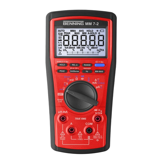
Device description 4.1 Device structure Device description Device structure Figure 6: BENNING MM 7-2 device structure 1 Front panel of the device 2 Rear panel of the device 3 Battery compartment 4 Holder for engaging a safety measuring line 5 Foldable stand 6 Jack for V, Ω, diode, capacitance, temperature 7 COM jack... -
Page 18: Figure 7 Rotary Switch
5 Capacitance measurement or diode 6 Temperature measurement test 7 Current measurement (A / mA) 8 Current measurement (μA) 9 Setting of the rotary switch 10 Voltage measurement (AutoV LoZ) 11 Device switched off (OFF) BENNING MM 7-2 5235 / 05/2022 en... -
Page 19: Figure 8 Digital Display
[} page 21]. Figure 8: Digital display 1 Display of functions 2 Battery status 3 Display range 4 Display of units 5 Bargraph indication 6 Polarity 5235 / 05/2022 en BENNING MM 7-2... -
Page 20: Functions
Capacitance Capacitance → diode measureme Temperatur °C → °F measureme A / mA A / mA‑DC → A / mA‑AC → A / mA‑AC+DC → 4‑20 mA (%) μA μA‑DC → μA‑AC → μA‑AC+DC Table 4: Selecting a function BENNING MM 7-2 5235 / 05/2022 en... -
Page 21: Min Max" Key
(MIN), average (AVG) and currently measured value (MAX AVG MIN). The minimum signal duration is 300 ms (V‑DC / A‑DC) or 460 ms (V‑AC / A‑AC), respectively. If the “MIN MAX” function is enabled, the automatic switch-off (APO, Auto-Power-Off) is disabled. 5235 / 05/2022 en BENNING MM 7-2... -
Page 22: Hz" Key
The device confirms each detection of a new maximum or minimum value with a brief acoustic signal. Press the “PEAK” key to toggle between the display of the maximum value (MAX) and the minimum value (MIN). BENNING MM 7-2 5235 / 05/2022 en... -
Page 23: Hold" Key
Press the “REL Δ” key to enable or disable the “Relative value” function. With the function being enabled, the “Δ” symbol is shown on the digital display. 5235 / 05/2022 en BENNING MM 7-2... -
Page 24: Range" Key
“InEr” (‘Input error’) will be shown on the digital display to protect the device. A non-functioning visual and acoustic jack control indicates a defective fuse. BENNING MM 7-2 5235 / 05/2022 en... -
Page 25: Further Setting Options
(switch position “OFF”). – Press and hold the “PEAK” key and simultaneously set any switch position from the “OFF” position of the rotary switch of the device until “F” is shown on the digital display. 5235 / 05/2022 en BENNING MM 7-2... -
Page 26: Measuring Ranges
Peak values including DC bias voltage <1 000 mV peak Measuring accuracy plus 1 % at >5 ... 7 kHz, 1 000 V measuring range: Not specified • Input resistance: 10 MΩ II, 75 pF (140 pF in the 600 mV range) • Display value with short-circuited safety measuring lines: <50 digits BENNING MM 7-2 5235 / 05/2022 en... -
Page 27: Table 8 Ac Voltage Ranges (Hfr V-Ac)
• Minimum sensitivity: >1 V‑AC (50 / 60 Hz), >1.0 V‑DC, <-1.0 V‑DC) • Input resistance: Initially 2.1 kΩ II, 140 pF, rapidly increasing for display values >50 V. Typical input resistances depending on the display values: 12 kΩ at 100 V, 90 kΩ at 300 V, 300 kΩ at 600 V, 670 kΩ at 1 000 V 5235 / 05/2022 en BENNING MM 7-2... -
Page 28: Current Ranges
• 10 … 20 A: The maximum measuring time is 30 seconds (pause >15 minutes). 4 - 20 mA DC current loop (%) Measuring range Resolution Measuring accuracy 0 % (4 mA) … 100 % (20 mA) 0.01 % ±25 digits Table 13: 4 - 20 mA DC current loop (%) BENNING MM 7-2 5235 / 05/2022 en... -
Page 29: Resistance Ranges
Table 16: Diode test • Open-circuit voltage: <3.1 V‑DC; testing current: approx. 0.35 mA • Forward voltage <0.85 V: Brief acoustic signal of the buzzer; forward voltage <0.1 V: Long acoustic signal of the buzzer • Optical indication: Display illumination 5235 / 05/2022 en BENNING MM 7-2... -
Page 30: Capacitance Ranges
• Measuring accuracy: ±(0.05 % + 5 digits) 5 V logic-level frequency ranges Measuring range Resolution Measuring accuracy 5 Hz … 1 MHz Max. 0.001 Hz ±(0.002 % + 4 digits) Table 19: 5 V logic-level frequency ranges (Hz) • Min. sensitivity: >3.0 V (square) peak • Pulse width: >0.5 μs BENNING MM 7-2 5235 / 05/2022 en... -
Page 31: Temperature Ranges
• Measuring accuracy: ±1.5 °C (±1.8 °F) The measuring accuracy applies to stable ambient temperatures lower than ±1° C. After a change of the ambient temperature of ±2 °C, the measuring accuracy specifications will apply after 2 hours. 5235 / 05/2022 en BENNING MM 7-2... -
Page 32: Operation
• Use the device only in electric circuits up to overvoltage category CAT III with a conductor for a maximum of 1 000 V or up to overvoltage category CAT IV with a conductor for a maximum of 600 V to earth. BENNING MM 7-2 5235 / 05/2022 en... -
Page 33: Connecting The Safety Measuring Lines
Please observe the information for visual and acoustic jack control [} page 24]. 3. Measurements or tests with test probes in electric circuits of overvoltage category CAT III or CAT IV: Attach the protective caps to the contact tips of the safety measuring lines. 5235 / 05/2022 en BENNING MM 7-2... -
Page 34: Voltage, Frequency Or Duty Cycle Measurement
2.1 kΩ in order to suppress unwanted inductive and capacitive voltages (reactive voltages). 4. Bring the safety measuring lines into contact with the measuring points and read the measured value on the digital display. BENNING MM 7-2 5235 / 05/2022 en... -
Page 35: Current Or Frequency Measurement
“Hz” key. 4. Bring the safety measuring lines into contact with the measuring points and read the measured value on the digital display. 5235 / 05/2022 en BENNING MM 7-2... -
Page 36: Resistance Measurement Or Continuity Testing
– Resistance measurement: Read the measured value. – Continuity test: When the buzzer sounds (acoustic signal) and the digital display lights, the line resistance between the COM jack and the jack for continuity testing falls below the value of 100 to 420 Ω. BENNING MM 7-2 5235 / 05/2022 en... -
Page 37: Capacitance Measurement Or Diode Testing
“000”: indicates a short circuit inside the diode. “OL”: indicates an interruption inside the diode. – Diode applied in reverse direction: “OL” is displayed. In case of defective diodes, “000” or other values will be displayed. 5235 / 05/2022 en BENNING MM 7-2... -
Page 38: Temperature Measurement
– Positive pole into the jack for temperature measurement 4. Position the contact point (end of the wire temperature sensor) at the measuring point. 5. Wait until the measured value on the digital display has stabilised and read it. BENNING MM 7-2 5235 / 05/2022 en... -
Page 39: Voltage Indicator
Requirements • Please observe the requirements for measuring [} page 32]. • Make sure that no voltage is applied to the jacks of the device. Remove any connected safety measuring lines. Figure 14: Non-contact phase testing 5235 / 05/2022 en BENNING MM 7-2... - Page 40 Practical tip Interruptions (cable breaks) in exposed cables – e. g. in cable reels, chains of light, etc. – can be traced from the feeding point (phase) to the point of interruption. Functional range: ≥230 V BENNING MM 7-2 5235 / 05/2022 en...
-
Page 41: External Conductor Or Phase Testing
4. Bring the safety measuring line into contact with the measuring point (system part). If the device detects the phase of an earthed AC voltage, the symbol “EF‑H” or “EF‑L” will disappear. A bargraph indication and an acoustic signal indicate the strength of the electric field. 5235 / 05/2022 en BENNING MM 7-2... -
Page 42: Maintenance
Procedure 1. Remove the device from the measuring point. 2. Disconnect the safety measuring lines from the device. 3. Set the rotary switch of the device to switch position “OFF”. BENNING MM 7-2 5235 / 05/2022 en... -
Page 43: Cleaning The Device
3. In case of electrolyte contamination or white deposits in the area of the battery or the battery compartment, clean the batteries and these areas by means of a clean and dry cloth. Replace the batteries [} page 44], if necessary. 5235 / 05/2022 en BENNING MM 7-2... -
Page 44: Replacing The Batteries
6. Place the battery compartment back into the device and tighten the two screws. Calibrating the device Benning guarantees compliance with this technical and accuracy specifications stated in this operating manual for the first 12 months after the delivery date. To maintain accuracy of the measuring results, make sure that the device is recalibrated in annual intervals by the BENNING Service [} page 9] . -
Page 45: Replacing The Fuses
8. Carefully reassemble the bottom of the housing and the front part. For this, make sure that the rotary switch is in the “OFF” position. 9. Tighten the six screws of the housing. 10. Place the battery compartment back into the device and tighten the two screws. 5235 / 05/2022 en BENNING MM 7-2... -
Page 46: Technical Data
To be used inside buildings in dry environments Storage (remove the batteries from the device) Ambient temperature -20 … 60 °C (do not permanently expose the device to sunlight) Max. relative air humidity 80 % RH Table 23: Technical data BENNING MM 7-2 5235 / 05/2022 en... -
Page 47: Disposal And Environmental Protection
Disposal and environmental protection 6.6 Replacing the fuses Disposal and environmental protection At the end of product life, dispose of the unserviceable device and the batteries via appropriate collecting facilities provided in your community. 5235 / 05/2022 en BENNING MM 7-2... -
Page 48: Index
23 Selecting 20 Voltage indicator 22 Further information 7 Basic knowledge 7 Fuse Battery Replacing 45 Replacing 44 BENNING MM 7-2 7 History 8 Holder of rights 2 Calibrating 44 Capacitance measurement 37 Capacitance ranges 30 Cleaning 43 Intended use 12... - Page 49 Service & Support Technical support 9 Standards applied 10 Symbols Device 11 Operating manual 11 Target group 7 Technical data 46 Technical support 9 Temperature measurement 38 Temperature unit 25 Temperature ranges 31 5235 / 05/2022 en BENNING MM 7-2...
- Page 50 BENNING Elektrotechnik und Elektronik GmbH & Co. KG Münsterstraße 135 - 137 D - 46397 Bocholt Phone: +49 2871 93-0 Fax: +49 2871 93-429 Internet: www.benning.de E-Mail: duspol@benning.de BENNING MM 7-2 5235 / 05/2022 en...