Table of Contents
Advertisement
Quick Links
Advertisement
Table of Contents

Related Manuals for HELIX HLT3000 3D


Summary of Contents for HELIX HLT3000 3D
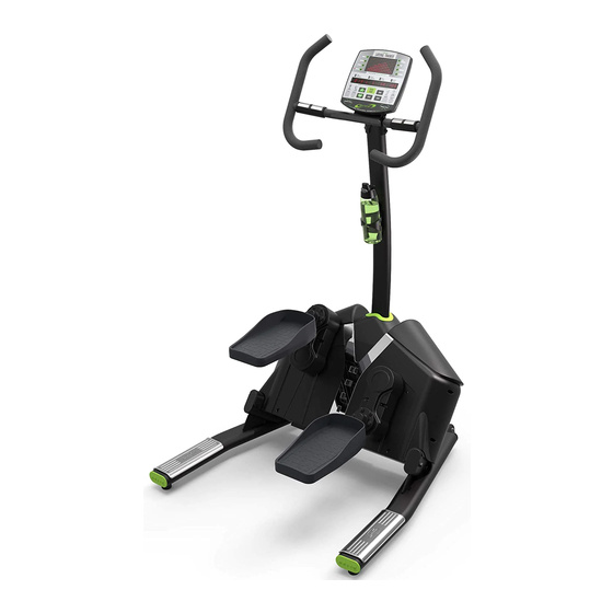
- Page 1 Aerobic Lateral Trainer...
-
Page 2: Safety Precautions
11. This machine is only intended and only warranted to be used within indoor enclosed spaces and is not warranted for use anywhere that could be viewed as not “indoor space.” IMPORTANT: THE MAXIMUM RECOMMENDED WEIGHT CAPACITY FOR YOUR Helix is 300lbs/ 136kg per user. -
Page 3: Table Of Contents
TABLE OF CONTENTS 1 SAFETY PRECAUTIONS 2 TABLE OF CONTENTS 3 PARTS IDENTIFICATION Hardware Bags Exploded View Diagram Parts Checklist 4 ASSEMBLY 7-13 Stabilizer Installation Upright Installation Dome Cover Installation Water Bottle Holder Installation Handlebar Installation Console Installation 11-12 5 UNPACKING 6 CONSOLE OPERATION 14-21 Console Basics 14-14 Program Operation 16-18 Key Functions Engineering Mode 20-21 7 PRODUCT MAINTENANCE 22-23... -
Page 4: Parts Identification
Bags of hardware are marked with the step number in which they are used. It is recommended that these parts not be removed from the individual bags until each step of the process to avoid mixing up or confusing parts. If you find that you are missing parts or the bag for a step is missing, please contact Helix or your dealer to receive those items. You can refer to the parts by the “step number” for ease of description. PAGE 4... -
Page 5: Exploded View Diagram
PARTS IDENTIFICATION EXPLODED VIEW DIAGRAM Item# Part Description Main Frame Rubber Gasket for Upright Electronic Console Display Center Upright Post Left and Right Handlebars Console Mounting Plate Water Bottle Holder Bolts Console Mounting Bolts Center Upright Mounting Bolts Handlebar Bolts Water Bottle Holder Console Mounting Plate Bolts Dome Shaped Cover... -
Page 6: Parts Checklist
LEVELER IMPORTANT: Read all instructions carefully. Assemble the Helix in accordance with the steps in the manual. All tools required for assembly are included with your Helix. Lay out all parts on the floor. Make sure that you have all the parts listed below before beginning assembly. In case of a discrepancy, please contact our Customer Service Department at the email address or customer service number listed on the back page of this Owner’s Manual. -
Page 7: Assembly
After securing the upright, at the base of the upright connect the wiring harness coming from the upright to the wiring harness coming from the main body of the Helix Figure #2. After these are connected, tuck the wire and connection into the upright and be sure the wire is clear of the large... -
Page 8: Dome Cover Installation
ASSEMBLY DOME COVER INSTALLATION Step 3: Align the front of the dome cover as shown and slide down the upright post. Figure #3 Slide the cover down to the bottom of the center upright tube and fit the tabs into the holes in the lower plastic housing to fit snugly in place as shown Figure #4 Step 4: Slide the rubber gasket down the center upright tube and push into place as shown. Figure #5 and Figure #6 PAGE 8... -
Page 9: Water Bottle Holder Installation
ASSEMBLY WATER BOTTLE HOLDER INSTALLATION Step 5: Secure the water bottle holder onto the upright as shown. First, locate the bolt holes in the upright, as shown in Figure #7. Insert one bolt into the hole in the lower part of the bottle holder. Thread it into place in the lower hole in the upright as shown in Figure #8. -
Page 10: Handlebar Installation
ASSEMBLY HANDLEBAR INSTALLATION Wire Tie Wire Tie Step 6: Untie the wire tie in the upright and do not remove. Attach the end of the wire tie coming out of the hole for the handlebar to the pulse grip wire coming out of the handlebar bracket as show in Figure #11. -
Page 11: Console Installation
ASSEMBLY CONSOLE INSTALLATION Step 8: To install the console bracket, feed the three sets of wires through the hole in the bracket, as shown in Figure #14 and Figure #15. Then thread the four bolts to secure the console bracket onto the upright, as shown in Figure #16 and Figure #17. - Page 12 ASSEMBLY Step 9: Three wires come out of the upright, and three wires come out of the console. Match the connectors and connect these wires as shown in Figure #20. The small wires are not slide- specific; it doesn’t matter if you connect them to the right or left handlebar wires. Just match the connectors and connect the wires.
-
Page 13: Unpacking
Step 11: Tilt the machine back and remove two bolts holding the Helix to the wooden base. Then place machine back level. Next remove the zip ties holding the rear of the Helix to the wooden base. Figure #18 INSTALL LEVELER FEET... -
Page 14: Console Operation
Figure 1 Figure 2 Start-up Mode: Exercise on the Helix. The console will beep and light up. The console will appear as shown above in Figure 1 and Figure 2. Stand-by Mode: When the Helix is not in use for three minutes, it will automatically enter sleep mode. - Page 15 CONSOLE OPERATION The profile of workout programs appears on the dot matrix screen (see right). The vertical height of columns represents resistance level. Horizontal movement, from left to right, represents the passage of time. The blinking LED indicates the current, active, part of the workout.
-
Page 16: Program Operation
CONSOLE OPERATION PROGRAM OPERATION Exercise on the product. Then select a workout program. The active program’s LED will light. Press the ENTER key to confirm your choice. The message “SET WEIGHT 150LB” will appear. Press UP/DOWN keys to select your weight. Then press the ENTER key to confirm your choice. The message “SET TIME 000” will appear. Press UP/DOWN keys to select your preferred workout time. Then press the ENTER key to confirm your choice. The message “SET LEVEL 1” will appear. - Page 17 CONSOLE OPERATION Workout Profiles: MANUAL PROGRAM RANDOM PROGRAM INTERVAL PROGRAM H.R.C PROGRAM HELIX INTERVALS HIIT MOUNTAIN PROGRAM OLYMPIAN PROGRAM Heart Rate Control Workout: When the heart rate control workout is selected, the console will prompt you for more information. The message to set user weight will appear. Set user weight as explained above.
- Page 18 CONSOLE OPERATION Cool Down: When a workout program ends, the console enters COOL DOWN mode. The message “COOL DOWN” will appear. This message appears for five seconds. During the COOL DOWN period, press the UP/DOWN keys to adjust the resistance level, if desired. The duration of the COOL DOWN period depends on the duration of the workout. Alternatively, you can activate the COOL down mode at any time during a workout by pressing the CLEAR key.
-
Page 19: Key Functions
CONSOLE OPERATION KEY FUNCTIONS ENTER key - To confirm entries and proceed to next entry. QUICKSTART key - Once the computer powers on, this button will pre-set the workout to start at Level 1 Manual mode and 20 minute period. SCAN key - The workout feedback screen has two rows. The top row shows TIME, LEVEL, RPM, WATTS. -
Page 20: Engineering Mode
“QUICK START” and “CLEAR” keys for three seconds. 2. The software version will appear, for example, “HELIX VER-13.” Press the “ENTER” key to view other settings. 3. “FINISH 20151223” (with different numbers at the end) will appear. Press the “ENTER”... - Page 21 CONSOLE OPERATION 6. “ENGLISH” or “METRIC” will appear. If you do not want to change the unit of measure, press the “ENTER” key to view other settings. If you do want to change the unit of measure, press the “UP” or “DOWN” key until your preference appears. Then press the “ENTER”...
- Page 22 PRODUCT MAINTENANCE MAINTENANCE TIPS Helix products require very little maintenance, but attention to the following points can ensure that your Helix lateral trainer looks good and performs well for years to come. Keep Product Level: During installation, place your Helix on a flat, level surface. Adjust the rubber leveler feet downward to ensure that the product is stable and does not rock or sway. Secure the leveler feet in position by screwing the nut upward, against the product frame.
-
Page 23: Product Maintenance
Adjust the Polar strap to maintain consistent contact with the skin. The heart rate value on this product is meant for comparison; it is not to be used for medical purposes. When a heart rate signal is detected, an LED will flash. If “P” appears in the pulse field, the signal is not clear. Maintain contact on the heart rate grips or adjust the position of your Polar heart rate strap. If you have questions about the maintenance of this product, please contact your product dealer or the Helix service department. Thank you. PAGE 23... - Page 24 If you cannot reach the dealer, please feel free to contact Helixco at 888-Helixco or by email to service@helixco.com Distributed by Helix Company, a division of M&S Distribution, Inc., 572 Freeport Street, Unit A, Boston, MA, 02122. MODEL No. HLT3000-3D Patented: US Patent No.