Advertisement
Advertisement
Table of Contents

Related Manuals for HELIX HLT3500


Summary of Contents for HELIX HLT3500
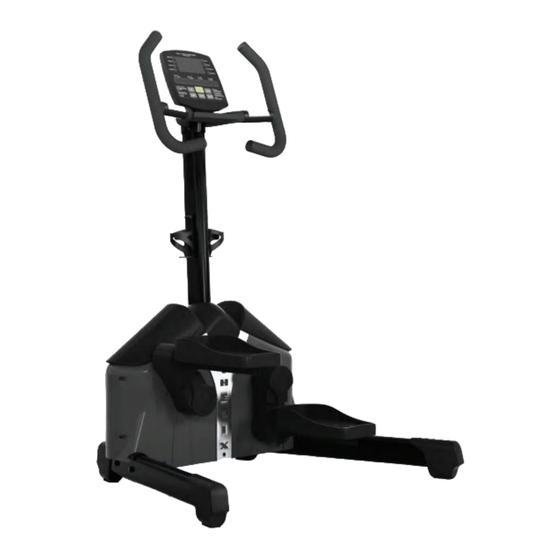
- Page 1 Aerobic Lateral Trainer...
- Page 3 IMPORTANT!!! THE MAXIMUM RECOMMENDED WEIGHT CAPACITY FOR YOUR Helix is 159Kg (350 lbs.) per user. WARNING: Before commencing with any exercise program, please consult your family physician. If at any time during exercise you feel faint, dizzy or experience pain, stop and consult your family physician.
-
Page 4: Pre-Assembly Check List
2/ BEFORE YOU BEGIN IMPORTANT: Read all instructions carefully. Assemble the Helix in accordance with the steps in the manual. Lay out all parts on the floor prior to assembly to make sure you have all the parts listed below. In case of discrepancy, please contact Customer Service at 888-435-4926 or service@helixco.com PRE-ASSEMBLY CHECK LIST Item #... - Page 5 It is recommended that these parts not be removed from the individual bags until each step of the process to avoid mixing up or confusing parts. If you find that you are missing parts or the bag for a step is missing, please contact Helix or your dealer to receive those items. You can refer to the parts by the “step number” for ease of description. STEP 3...
- Page 6 2/ CHANGING DISPLAY STANDARDS: ENGLISH/METRIC Instructions to change display standards To change the computer on the Helix HLT3500 from either Metric to Standard (English) or Standard (English) to Metric, please follow the instructions below carefully. Please note the computer must be completely off when starting this procedure.
- Page 7 Step 1: Put the product on the floor and remove the top box cover to reveal the Helix as show above. Where the box corners are printed “OPEN”, cut or tear the box and separate these corners. Lay the sides flat to the floor Remove all parts from the box leaving just the main body of the machine on the bottom of the box. remove all parts from their plastic bags and organize on the floor beside the Helix.
- Page 8 3/ ASSEMBLY Step 3: Step 4: Step 3: Insert the Stabilizer Leg assembly bolts into the legs and secure as shown. Tighten these bolts firmly. Step 4: Align the bolt holes on the pedal frame with the bolts on the yoke of the Crank arm. These two parts should fit together to allow the Pedal Frame and yoke to become even and flush with each other.
- Page 9 ASSEMBLY OF THE TRANSPORT PLATE Step 5: Find a box or step to place one stabilizer leg of the Helix onto in order to raise one side off the ground. Install the transport plate with the 4 bolts as shown.
- Page 10 3/ ASSEMBLY Hole to feed hand pulse wire one on each Main computer wire side of upright Step 6: Install the Handlebars one side at a time. First insert the wire coming out from the handlebar into the upright and feed wires through the opening in the top of the upright post.
- Page 11 3/ ASSEMBLY ASSEMBLY OF THE CENTER UPRIGHT TUBE Step 7: Place the upright post onto the main frame and install four (4) Tapered Allen head bolts to tightly secure. After securing these bolts, connect the wire from the frame to the wire from the upright tube. Slide the Dome Cover down the post.
- Page 12 3/ ASSEMBLY Feed 3 wires carefully through this hole Step 8: Install the Computer mounting plate by first pulling three sets of wires (Two (2) from the handle bars and one from the upright) through the hole in the center of the plate. Then making sure the wires are not pinched in between the plate and the bracket, align the four holes in the plate with the four bolt holes (Two (2) on each handlebar bracket) on the handle bar brackets and insert four phillips head bolts and hand tighten only.
- Page 13 3/ ASSEMBLY Slide onto bracket Beware not to pinch computer wires Step 9: Install Computer: Connect the three wires coming out of the computer mounting plate with the three wires coming out of the back of the computer. Simply snap the connectors together.
-
Page 14: Step 12: Installing Batteries
3/ ASSEMBLY Step 11: Install Bottle Cages: Take one bottle cage and find two (2) bottle cage bolts. Align the bottle cage holes with the screw holes on either side of the upright. Install and tighten two bottle cage bolts. Do not over tighten. Repeat the process for the second water bottle. Step 12: Installing Batteries: Remove the cover to the battery compartment by pressing in the tab by the arrow shown above. - Page 15 The display will scroll from Figure-1, to Figure-2 above) Stand-by Mode: When the Helix is not in use for three (3) minutes, it will automatically enter into the Sleep. There will be no computer display in that mode.
-
Page 16: Dot Matrix Display
These program keys can be used to directly choose a program. Alternatively, the user can scroll the programs with the up or down key. When the Helix computer first starts, this scrolling message will read across the Data Display Screen. “CHOOSE PROGRAM OR QUICK START” Pressing the QUICK START key in the center of the console, will begin the workout immediately with a default time of 20 minutes and Level 1 of Manual mode. - Page 17 5/ COMPUTER OPERATING INSTRUCTIONS Quick Start: Program Selection: When the computer first starts, the user can choose one of eight program buttons on either side of the large dot matrix display; Manual, Random, Interval, Heart Rate Control, Valley, Rolling, Mountain or Olympian. Choose the program by pushing the button beside the program name or by scrolling through the choices with the up or down key.
- Page 18 5/ COMPUTER OPERATING INSTRUCTIONS Heart Rate Control Program If the user chooses the Heart Rate Control program, the user will again be asked to enter their weight as above. The user will then be asked to set the desired heart rate. The message will read “SET HRC 80”. Using the up and down keys, set the desired heart rate.
-
Page 19: Summary Mode
5/ COMPUTER OPERATING INSTRUCTIONS Cool Down: At any time during the workout, press the CLEAR key to proceed directly into the Cool Down mode. Also, at the end of the workout time, the computer will automatically proceed into the Cool Down Mode. The message will display “COOL DOWN”, and will display for 5 seconds. -
Page 20: Heart Rate Display
5/ COMPUTER OPERATING INSTRUCTIONS Heart Rate Display Heart rate will be display by either holding both hands on the hand grip sensors or by wearing a Polar compatible Heart rate chest strap (not included). When holding the hand grip sensors or when wearing the chest strap, the dot will flash in the PULSE field. If “P” is showing in the Pulse field, please either adjust your grip or adjust the Polar Chest strap to improve the connection. -
Page 21: Program Keys
5/ COMPUTER OPERATING INSTRUCTIONS DOWN Key – Used to select workout Program, adjust Weight, adjust Time, adjust Heart Rate Control value and to adjust resistance level during setup. Using this key, the resistance level can be changed during a workout. PROGRAM KEYS There are eight (8) program keys on the left and right side of the Large Dot Matrix display. - Page 24 Distributed under license from Kriptonite Corp by Helixco, a division of M & S Distribution, Inc, 136 Arlington Street, Boston, Ma 02116. This product is patented in the US and other International Patents and patents pending. US Patent Number 7,108,638 Helix® is a registered trademark of M & S Distribution, Inc. All rights reserved.