HELIX H1000 Assembly Manual
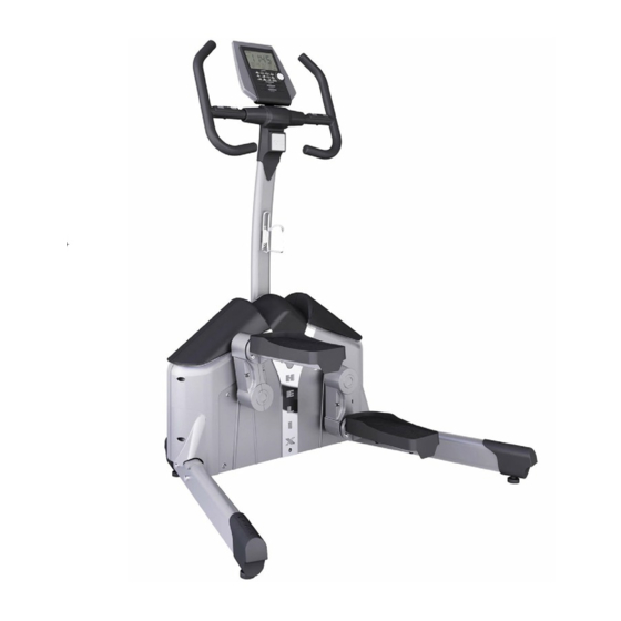
Aerobic lateral trainer
Hide thumbs
Also See for H1000:
- Assembly manual (10 pages) ,
- Instruction manual (5 pages) ,
- Instruction manual (5 pages)

Related Manuals for HELIX H1000


Summary of Contents for HELIX H1000
- Page 1 Aerobic Lateral Trainer Please read carefuly before using.
- Page 3 10. This machine is intended for household use only. It is not designed for commercial use. IMPORTANT!!! THE MAXIMUM RECOMMENDED WEIGHT CAPACITY FOR YOUR Helix is 130Kg (286 lbs.) per user.
- Page 5 If you find that you are missing parts or the bag for a step is missing, please contact Helix or your dealer to receive those items. You can refer to the parts by the “step number” for ease of description.
- Page 6 - 6 -...
- Page 7 IMPORTANT: Read all instructions carefully. Assemble the Helix in accordance with the steps in the manual. All tools required for assembly are included with your Helix. Lay out all parts on the floor. Make sure that you have all the parts listed below before beginning assembly. In case of a discrepancy, please contact our Customer Service Department at the email address or customer service number listed on the back page of this Owner’s Manual.
- Page 8 STEP 1: Put the product on the floor and remove the top box cover to reveal the Helix as show above. Where the box corners are printed “OPEN”, cut or tear the box and separate these corners. Lay the sides flat to the floor.
- Page 9 3/ ASSEMBLY - PEDALS STEP 4: Using the 6 Hex head bolts and washers from STEP 4 Plastic Parts Bag, install one bolt and one washer in the top bolt of the plate as shown in Figure #5. On the Pedal assembly make note of the slot in the Slot round disk as shown in Figure #6.
- Page 10 Upright Tube. on the front of the Center Upright sides and lifting off of the Helix. (See Tube. (See Figure #2) Figure #1) above. The back can be determined by the...
- Page 11 3/ ASSEMBLY - CABLES - COVER AND HANDLE BARS STEP 8: At the bottom of the upright there are two cables that connect to each other with the black connectors at the end. The black connectors only connect in one direction. Gently try to connect the male and female connectors and if not easy to connect, flip over one connector and try again.
- Page 12 3/ ASSEMBLY - COVER AND HANDLE BARS STEP 12: There should now be 3 wires. two coming from the handle bars and one that you held from the upright when installing the handle bars. Hold all three wires together as shown in Figure #1 above. Take Top Cover (part #9) and position with the notch in the rear to allow wires to come out.
- Page 13 3/ ASSEMBLY - COVER AND HANDLE BARS WATER BOTTLE HOLDER INSTALLATION STEP 13: Find the two bolt holes with bolts pre-installed in the Center Upright Post and remove those bolts (Figure #1) Once bolts holes are empty (Figure #2) hold the water bottle holder up to the post as shown and install a bolt in the lower hole in the water bottle holder bracket (Figure #3) and through to the lower bolt hole on the upright.
- Page 14 4/ GETTING STARTED - COMPUTER STEP 1: INITIAL SET-UP When the power supply is plugged into a wall outlet for the first time, the computer console will power up with a brief test mode. Following the test mode, the console will wait for input to set the date and time. Figure 1 Figure 2 Setting the clock: Using the round dial on the console, the year, month and day will be entered.
- Page 15 4/ GETTING STARTED - COMPUTER CONSOLE FUNCTIONS: TIME: Counting up - No preset target. The timer will count up from 00:00 to maximum 99:59. Counting down - The timer will count down from the users preset time. SPEED: Displays the current training speed. RPM: Displays the current training cadence.
- Page 16 4/ GETTING STARTED - COMPUTER SETTING THE TIME, DISTANCE, CALORIES, AND PULSE IN EACH PROGRAM. For each Workout Program, after the selection of the workout program, the computer will prompt the user to select the TIME, DISTANCE, CALORIES or PULSE goal for the workout. (Heart Rate Program HRC will not allow PULSE entry ).
- Page 17 5/ COMPUTER BUTTON FUNCTIONS Figure 8 Figure 9 Figure 10 Figure 11 Figure 12 Training in PROGRAM mode : When PROGRAM (PROG) mode is selected, rotating the dial clockwise or counterclockwise selects one of 12 programs. P01, through to P12. At each selection with a moment, the image in the bottom left screen will change from the P01 to the program profile for a brief view of that program.
- Page 18 5/ COMPUTER BUTTON FUNCTIONS Training in USER PROGRAM: User Program allows for a custom profile to be selected. Each segment of the workout is adjusted by rotating the dial to increase or decrease the level for that segment. After selecting USER by pressing the dial to confirm, the first column (segment) of the profile will begin to flash.
- Page 19 - 19 -...
- Page 20 For customer service, we first recommend you contact the dealer where you purchased the Helix. They will be able to resolve any issues the fastest. If you cannot reach the dealer, please feel free to contact Helixco at 888-Helixco or by email to customer@helixco.com Distributed under license from Kriptonite Corp by Helixco, a division of M &...