Siemens LDS 6 Operating Instructions Manual
In situ laser gas analyzers
Hide thumbs
Also See for LDS 6:
- Operating instructions manual (102 pages) ,
- Compact operating instructions (70 pages) ,
- Product information (30 pages)
Table of Contents
Advertisement
Quick Links
Continuous Gas Analysis
In Situ Laser Gas Analyzers
LDS 6
Operating Instructions
7MB6121-.....-....
01/2022
A5E00295894-10
General information
Technical information
Installation guidelines
Operation
Alarms
Maintenance and service
Technical specifications
Dimensional drawings
ESD guidelines
List of abbreviations
1
2
3
4
5
6
7
8
A
B
Advertisement
Table of Contents

Related Manuals for Siemens LDS 6


Summary of Contents for Siemens LDS 6
- Page 1 General information Technical information Installation guidelines Continuous Gas Analysis Operation In Situ Laser Gas Analyzers LDS 6 Alarms Maintenance and service Operating Instructions Technical specifications Dimensional drawings ESD guidelines List of abbreviations 7MB6121-..-..01/2022 A5E00295894-10...
- Page 2 Note the following: WARNING Siemens products may only be used for the applications described in the catalog and in the relevant technical documentation. If products and components from other manufacturers are used, these must be recommended or approved by Siemens. Proper transport, storage, installation, assembly, commissioning, operation and maintenance are required to ensure that the products operate safely and without any problems.
-
Page 3: Table Of Contents
3.3.1 Power supply connections....................26 3.3.2 Hybrid cable connection..................... 28 3.3.3 Signal cable connection ..................... 29 3.3.4 Pin assignment of LDS 6..................... 31 Three channel system ......................32 3.4.1 External power supply......................32 3.4.2 External power supply......................33 3.4.3 Three channel hybrid cable connection ................34 Flange installation requirements .................. - Page 4 Reconfiguration of the path length ..................67 Technical specifications ........................69 Central unit ........................69 Dimensional drawings ......................... 73 ESD guidelines ............................. 77 ESD guidelines ........................77 List of abbreviations ..........................79 List of Abbreviations ......................79 Index ..............................83 LDS 6 Operating Instructions, 01/2022, A5E00295894-10...
-
Page 5: General Information
Siemens’ products and solutions undergo continuous development to make them more secure. Siemens strongly recommends that product updates are applied as soon as they are available and that the latest product versions are used. Use of product versions that are no longer supported, and failure to apply the latest updates may increase customer’s exposure to cyber... -
Page 6: Purpose Of This Documentation
Siemens’ products and solutions undergo continuous development to make them more secure. Siemens strongly recommends that product updates are applied as soon as they are available and that the latest product versions are used. Use of product versions that are no longer supported, and failure to apply the latest updates may increase customer’s exposure to cyber... -
Page 7: Special Information And Warnings
All obligations on the part of Siemens AG are contained in the respective sales contract, which also contains the complete and solely applicable liability provisions. The provisions defined in the sales contract for the responsibility for defects are neither extended nor limited by the remarks in this document. -
Page 8: Standards And Regulations
시기 바라며 가정 외의 지역에서 사용하는 것을 목적으로 합니다. Class A device This device is classified as having electromagnetic resistance suitable for industrial use (Class A) and may be used universally, apart from in domestic use. LDS 6 Operating Instructions, 01/2022, A5E00295894-10... -
Page 9: Technical Information
General description Overview LDS 6 is a diode laser gas analyzer with a measuring principle based on the specific light absorption of different gas components. LDS 6 is suitable for fast and non-contact measurement of gas concentrations or temperatures in process or flue gases. One or two signals from up to three measuring points are processed simultaneously by one central analyzer unit. - Page 10 • Exceeding of a lower or upper alarm level for the measured variable • Transmitted amount of light exceeding an upper or lower limit Application The LDS 6 laser gas analyzer is suitable for a wide range of applications. The most common of them are: • Process optimization •...
-
Page 11: Design
Design The gas analyzer LDS 6 consists of a central unit and up to three in-situ optics housings. The connection between the central unit and the optics housings is established by a so-called hybrid cable, which contains optical fibers and copper wires. An additional cable connects the transmitter and receiver parts of the cross-duct optics housings. - Page 12 • Large LCD field for simultaneous display of measurement result and device status • Contrast of the LCD field is adjustable via the menu • LED background illumination of the display with energy-saving function • Easy-to-clean membrane touch pad with softkeys LDS 6 Operating Instructions, 01/2022, A5E00295894-10...
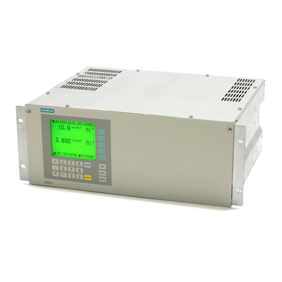
- Page 13 • Menu-driven operation for parameterization and diagnostics • Operation support in plain text Figure 2-3 LDS 6 central unit, membrane keyboard and graphic display Inputs and outputs • One to three measurement channels with hybrid connections for the optics housings at the measuring points •...
- Page 14 LDSComm (LDS Communication Client) to be installed on the remote computer. All aspects of LDS 6 can be controlled in this way. For the operation of the LDS 6 using LDSComm software refer to the LDSComm Manual (A5E02183317).
- Page 15 (https:// support.industry.siemens.com/cs/ae/en/ps/17702/man) Operating Instructions for use of the device in hazardous areas for LDS 6. Parts in contact with the process gases The optics housings normally do not come into contact with the process gas, since purging with a gaseous media is applied at the process side. Stainless steel purging gas tubes in front of the optics housing windows immerse slightly into the process gas and thus limit the purging volume.
-
Page 16: Operating Principle
• Sheath material: oil-resistant polyurethane Operating principle LDS 6 is a gas analyzer employing single-line molecular absorption spectroscopy. A diode laser emits a beam of near-infrared light, which passes through the process gas and is detected by a receiver unit. The wavelength of the laser diode output is tuned to a gas-specific absorption line. - Page 17 Technical information 2.3 Operating principle since the quasi-monochromatic laser light is absorbed very selectively by only one specific molecular line in the scanned spectral range. Figure 2-6 Basic design of the LDS 6 LDS 6 Operating Instructions, 01/2022, A5E00295894-10...
-
Page 18: Configuration Examples
Figure 2-7 Typical transmitted light setup of LDS 6, in-situ A feature of the standard applications defined in the ordering data of the LDS 6 is that the typical process conditions are well-known and documented, and that the guaranteed measuring properties can be proven by reference installations. -
Page 19: Measurement Principle
Measurement principle Mode of operation The operation of LDS 6 is based on the fact that light propagating through a gas mixture will be absorbed according to Beer-Lambert's law at certain narrow wavelength bands. This is where the gases possess molecular transitions forming narrow absorption lines. - Page 20 In this case, the ratio of the absorbance of two characteristic lines of the same molecule measured at the same time in the same volume gives the actual temperature in the process gas. Typical measurable gases for LDS 6 are: • Oxygen (O ) for low and high pressure •...
- Page 21 Pressure The gas pressure can affect the line shape of the molecular absorption line. LDS 6 uses a special algorithm to adapt the line shape. Additionally, an external pressure signal can be fed to the instrument to provide complete compensation for the pressure influence including the density effect.
- Page 22 Optical path length The absorption values analyzed by the LDS 6 are typically small. As a result of Beer-Lambert’s law, the absorption of laser light depends on the optical path length within the gas. Therefore, the precision in determining the effective optical path length in the process might limit the overall precision of the measurement.
-
Page 23: Installation Guidelines
Electrical Safety DANGER Certain parts inside the gas analyzer LDS 6 carry dangerous voltages. The housing must be closed and grounded before switching on the analyzer. Death, personal injury and/or damage to persons and/or property may result if this is not observed. - Page 24 (e. g. binoculars). LDS 6 is compliant to laser class 1 according to EN 60825-1:2014 but also according to EN 60825-1:2007. Therefore laser class 1 can be used for health and safety evaluation according to Directive 2006/25/EC.
-
Page 25: General Installation Information
General installation information Mounting Conditions The central unit LDS 6 should be placed on a location which is dust-free and as free as possible from vibrations. Also ensure that the unit is not exposed to direct solar radiation. If these conditions can’t be fulfilled the LDS 6 must be installed in a cabinet with controlled environment. -
Page 26: Electrical Connections
There are three kinds of cables used for the LDS 6 depending on the application: • Hybrid cables for all types of systems except oxygen. These are installed between the LDS 6 and the transmitter optics housing. - Page 27 • A circuit-breaker shall be part of the installation. It must be provided in the immediate vicinity of the analyzer (see rating plate for loading capacity). It must also be labeled to correlate with the instrument. LDS 6 Operating Instructions, 01/2022, A5E00295894-10...
-
Page 28: Hybrid Cable Connection
For hybrid cables longer than 500 meters, an additional external power supply must be used. Figure 3-1 LDS 6 cable connections (here only channel 3 is connected) WARNING Removing the protective tube Keep the fiber end protected, by the protective tube, until it is time for connection. -
Page 29: Signal Cable Connection
3.3 Electrical connections 4. Sensor electronics voltage supply connection. 24 V/60 mA. 5. Signal output connections. 6. Network connection. Ethernet 10Base-T (RJ-45). See also Pin assignment of LDS 6 (Page 31) Signal cable connection (Page 29) 3.3.3 Signal cable connection CAUTION Signal voltages The signal voltages must be electrically isolated extra-low voltages (SELV). - Page 30 • In the case of analyzers with two or three channels, the analyzer sections are connected in parallel and the signal cables of each channel are independent. Only the power plug is common to all channels. LDS 6 Operating Instructions, 01/2022, A5E00295894-10...
-
Page 31: Pin Assignment Of Lds 6
Installation guidelines 3.3 Electrical connections 3.3.4 Pin assignment of LDS 6 The signal connection is carried out by using two DSUB connectors for each channel – one 15 pins and one 25 pins. Connector SUB-D 15F Analog outputs: Component 2... -
Page 32: Three Channel System
ATEX use whereas it is for ATEX. + – + – + – Figure 3-5 Connection of electrical cables for a 3 channel unit with cables longer than 500 m LDS 6 Operating Instructions, 01/2022, A5E00295894-10... -
Page 33: External Power Supply
3.4.2 External power supply The three channel version of LDS 6 uses an external power supply for the optics housings. The setup at the optics housing site is the same as for one and two channel systems. Also the ATEX version of the three channel LDS 6 is using an external power supply leaving the optics housings unaffected when a third channel is added. -
Page 34: Three Channel Hybrid Cable Connection
The flanges should be welded to the wall of the furnace or funnel as shown in the figure below. The flange must protrude at least 100 mm (4") from the wall and 0-30 mm (0-1.2") into the furnace/funnel. LDS 6 Operating Instructions, 01/2022, A5E00295894-10... -
Page 35: Installation Of Flanges
3.6 Installation of flanges Figure 3-8 LDS 6, Optics Housing CD 6 mounted on a process flange There are applications where furnace walls move due to variations in temperature. If the furnace walls move the optics housings will be miss-aligned and the measurement interrupted. To... - Page 36 If long purging tubes will be used, a greater effort should be made to align the flanges perfectly. Depending on the diameter and length of the stubs the possibility to align the optics housings is more restricted when long purging tubes are used. LDS 6 Operating Instructions, 01/2022, A5E00295894-10...
-
Page 37: Operation
LDS 6 is established, the system is ready to be used. The functions in the LDS 6 are controlled through a keypad on the front of the panel. A 5" LCD screen is used to present the measurement values as well as the instrument’s interface - the MMI. - Page 38 • The CLEAR key can be used to delete an input. The cursor then returns to the first position of the input field. Graphic Styling Elements Switching function (ON status). Switching function (OFF status, also status display in the status line). Entry into a subsequent menu. Triggering of a function. LDS 6 Operating Instructions, 01/2022, A5E00295894-10...
-
Page 39: Input Sequence Of Data
Service mode: signals are activated according to functions 71 and 77. Input sequence of data The figure "Input sequence interacting with LDS 6" below shows the input sequence of LDS 6. The circled numbers marking certain steps in the input sequence can also be found in the text following the figure. - Page 40 (exception: submenu "Analyzer status" which requires no password and is thus freely accessible). Analyzer status No code Calibration Access level 3 Measuring ranges Access level 1 Parameters Access level 1 Configuration Access level 2 LDS 6 Operating Instructions, 01/2022, A5E00295894-10...
- Page 41 For a channel with two components on a three-channel instrument you must first press the soft key next to the desired channel and thereafter (in the next window) press the soft key next to the desired component. LDS 6 Operating Instructions, 01/2022, A5E00295894-10...
-
Page 42: Analyzer Functions
Main menu item (section) Function Function designation number 5.2.1 Analyzer Configuration Analyzer Status Diagnostics Values Logbook Display Measuring Ranges 5.2.2 Zero Calibration Calibration (code 3) Span Calibration 5.2.3 Define Ranges Measuring Range (code 1) LDS 6 Operating Instructions, 01/2022, A5E00295894-10... -
Page 43: Analyzer Status
Ethernet On/Off 1* Analyzer-specific functions. 2* Channel-specific functions. 3* Component-specific functions. Some of the existing functions in other Siemens analyzers are not present in LDS 6, thus some function numbers may be missing in the preceding table. 4.3.2 Analyzer status Table 4-2 This display appears when pressing the first soft key ("Analyzer Status"), following the selection of... - Page 44 • OS Version: Version number of the Windows CE operative system running in the analyzer. • CE Software: Version number of the LDS 6-specific software. • CE Driver Software: Version number of the driver software. • Analyzer uC Drv.Software: Version number of the software running on the main micro controller.
-
Page 45: Calibration
Alarms (Page 59) 4.3.3 Calibration The LDS 6 is calibrated when delivered and does not normally require on site recalibration. Please consult Siemens support if recalibration is needed. NOTICE Never use functions 20 and 21 without having contacted Siemens service staff first. -
Page 46: Measuring Ranges
You can use this function to define a measuring range by assigning a start-of-scale value to the bottom value (4 mA) and a full-scale to the top value (20 mA) of the analog output. 41 Define Ranges Ch1 NH Start Value End Value 0.000 100.0 mg/Nm LDS 6 Operating Instructions, 01/2022, A5E00295894-10... -
Page 47: Parameters
53. The alarm is also signalled by a relay if this has been set up by function 71. The Relative 84.93 % triggering of a transmission alarm is registered in the logbook Set Nominal Value (function 3). Transm. Alarm On/Off LDS 6 Operating Instructions, 01/2022, A5E00295894-10... - Page 48 Basic Setting In addition you can carry out an LCD test by pressing the fourth soft key ("Test"). Various test patterns are then shown in succession. The test can be stopped by pressing ESC. Test LDS 6 Operating Instructions, 01/2022, A5E00295894-10...
-
Page 49: Configuration
Following selection of the configuration functions in the main menu by pressing the fifth soft key ("...Continue"), you can branch to the further configuration functions. Configuration Ch1 NH 70 Analog Output 71 Relay Outputs 72 Binary Inputs 73 Communication ...Continue LDS 6 Operating Instructions, 01/2022, A5E00295894-10... - Page 50 - if applicable (see also function 51). Stored Value (STO) Relay may be de-energized simultaneously with fault, transmission alarm or function control depending on the configuration of function Not Used Relay is not used. LDS 6 Operating Instructions, 01/2022, A5E00295894-10...
- Page 51 Binary input should be de-energized upon maintenance request signal Purging from purging equipment. External Maintenance Request Binary input should be de-energized upon fault maintenance request General from unspecified equipment. Not Used Binary input is not used. LDS 6 Operating Instructions, 01/2022, A5E00295894-10...
- Page 52 You can use this function to erase the working area data and the user data on the EE‐ 75 Erase Section Ch1 NH PROM. The factory data can never be erased. Erase Work Section Erase User Section LDS 6 Operating Instructions, 01/2022, A5E00295894-10...
- Page 53 Use soft key 1 to switch between the different modes. When an alarm occurs and the analog output is set to the latest measured value or 3/1 mA, the display of the concentration value in the measuring screen will be suppressed. LDS 6 Operating Instructions, 01/2022, A5E00295894-10...
- Page 54 Digits other than 0 and 1 are not accepted by the input field. After leaving function 80, the relays reassume their former status, prior to selection of the relay and binary test. The column "Binary" shows the current status of the binary inputs in this display. LDS 6 Operating Instructions, 01/2022, A5E00295894-10...
- Page 55 • Correction for temperature using a manual temperature value; • Correction for temperature using the internally calculated process temperature. Measuring Range: This is only possible if the LDS 6 is set up to measure the temperature of the [0.00 ]- 400.0 °C measuring point.
- Page 56 You can use this function to set the length of the measuring path for the specific channel. Please refer to the optics housing manual for more information on measuring the path length. 85 Path Length Ch1 NH [1.000] m LDS 6 Operating Instructions, 01/2022, A5E00295894-10...
- Page 57 LDS 6 and applications where water vapor is set manually. If this function is available in the current LDS 6, it can be activated in the adjacent display, otherwise it is not possible to access function 87.
-
Page 58: Watch Dog
Maintenance request alarm (Page 60) Watch dog In the unlikely event that the software in LDS 6 should crash it will reboot with the help of a watch dog. The instrument will be down for approximately 3 minutes if this should happen and then measure normally again. -
Page 59: Alarms
Alarms Alarm response LDS 6 is able to recognize and alarm for irregularities in its functions. There are five types of alarms that can be triggered depending on the nature of the error: • Maintenance request alarm • Faults alarm •... -
Page 60: Maintenance Request Alarm
External maintenance re‐ Maintenance request from outside. Check external equipment. quest Set clock LDS 6 has been switched off. Set date and time. Ambient Analyzer Ambient temperature or pressure is beyond limits Make sure that the ambient tem‐ specified in technical data. -
Page 61: Faults Alarm
Electronics failure in internal communication. Contact service. Data Flow Analyzer Electronics failure in internal communication. Contact service. Configuration Fault Chan‐ Configuration parameters failure. Contact service. Configuration Fault Ana‐ Configuration parameters failure. Contact service. lyzer LDS 6 Operating Instructions, 01/2022, A5E00295894-10... -
Page 62: Transmission Alarm
Possible Causes • Start-up procedure is active. • Analyzer is de-coded. • Analyzer is communicating with external service software. • Analyzer is shutting down. • Analyzer is saving data to EEProm or Flash memory. LDS 6 Operating Instructions, 01/2022, A5E00295894-10... -
Page 63: Maintenance And Service
Maintenance and service General about service and maintenance During normal use, the central unit LDS 6 requires no service. The optics housing with its optical surfaces will need regular maintenance. Depending on application and purging method, the interval of maintenance may vary from 1 to 12 months. -
Page 64: Ordering Of Spare Parts
5. Select a spare part and add it to your watch list. The watch list opens. 6. Click "Add to cart of Industry Mall". The Siemens Industry Mall opens and you can order your spare part. LDS 6 Operating Instructions, 01/2022, A5E00295894-10... -
Page 65: Calibration Verification
6.5 Reconfiguration of temperature compensation Calibration verification A calibration check of LDS 6 analyzer can be done using a reference cell arrangement (optional) containing a mixture of the measurement gas and nitrogen. The unit should be used in conjunction with the 2 meter hybrid cable that is delivered with each calibration verification kit. -
Page 66: Reconfiguration Of Pressure Compensation
4. Press MEAS to return to measurement screen. Press MEAS again to loose privileges. 5. The procedure has to be repeated for other channels. It is not necessary to repeat it for more than one component per channel since it is a channel specific function. LDS 6 Operating Instructions, 01/2022, A5E00295894-10... -
Page 67: Reconfiguration Of The Path Length
3. Press MEAS to return to measurement screen. Press MEAS again to loose privileges. 4. The procedure has to be repeated for other channels. It is not necessary to repeat the procedure for more than one component per channel since this function is a channel- specific function. LDS 6 Operating Instructions, 01/2022, A5E00295894-10... - Page 68 Maintenance and service 6.7 Reconfiguration of the path length LDS 6 Operating Instructions, 01/2022, A5E00295894-10...
-
Page 69: Technical Specifications
0 ... 3 vol. % / 0 ... 7.5 vol. % The maximum applicable measuring ranges can be found in the table of standard combinations. These can only be applied if the individual process conditions allow. We recommend to contact Siemens Technical Support for checking the applicability. LDS 6... - Page 70 +24 V DC, 50 VA is included in the scope of delivery Power consumption 50 W According to EN 61326 and standard classification of NAMUR NE21 Electric safety According to EN 61010-1, overvoltage classification II Fuse specifications 100 ... 240 V: T2.5L250V LDS 6 Operating Instructions, 01/2022, A5E00295894-10...
- Page 71 Purity better than 99.7 %. For oxygen measurements, an oxygen content <0.01 % is recommended in the purging gas (optical path length ≥1 m (3 ft), min. 5 % oxygen in the process gas) LDS 6 Operating Instructions, 01/2022, A5E00295894-10...
- Page 72 Technical specifications 7.1 Central unit Purging with instrument air, nitrogen Maximum flow 500 l/min Dew point Dew point below ambient temperature, condensation on the optics must be avoided LDS 6 Operating Instructions, 01/2022, A5E00295894-10...
-
Page 73: Dimensional Drawings
Dimensional drawings Central unit The central unit will fit in a standard 19" rack. The dimensions are shown below. Figure 8-1 Dimensional drawings of the central unit – LDS 6 (all values are in millimeters) LDS 6 Operating Instructions, 01/2022, A5E00295894-10... - Page 74 Dimensional drawings Connections Figure 8-2 LDS 6, three-channel 19" central unit, optical and electrical connections LDS 6 Operating Instructions, 01/2022, A5E00295894-10...
- Page 75 Relay 4 The relay is de-energized in the shown contact position Relay 3 Relay 2 Relay 1 Contact loading max. 24 V/1 A, AC/DC Figure 8-3 Pin assignment of the LDS 6 central unit LDS 6 Operating Instructions, 01/2022, A5E00295894-10...
- Page 76 Dimensional drawings LDS 6 Operating Instructions, 01/2022, A5E00295894-10...
-
Page 77: Esd Guidelines
Anyone who is not connected to the electrical potential of their surroundings can be electrostatically charged. The figure below shows the maximum electrostatic voltage which may build up on a person coming into contact with the materials indicated. These values correspond to IEC 801-2 specifications. LDS 6 Operating Instructions, 01/2022, A5E00295894-10... - Page 78 In this way, the discharged energy can not affect the sensitive devices. Discharge your body before you start taking any measurements on a module. Do so by touching grounded metallic parts. Always use grounded measuring instruments. LDS 6 Operating Instructions, 01/2022, A5E00295894-10...
-
Page 79: List Of Abbreviations
European Union Explosive atmosphere FPGA Field-programmable Gate Array Water Hydrogen chloride Hydrogen fluoride Hectopascal Height unit for computer housings, 1 HU ≙ 1¾" ≙ 44.45 mm Kelvin Kilohertz kΩ Kiloohms Kilopascal Local Area Network LDS 6 Operating Instructions, 01/2022, A5E00295894-10... - Page 80 Standards working committee for measuring and control technology in the chemical industry Ammonia (dry) Standard cubic meter Oxygen Process Automation Personal Computer Printed Circuit Board Process Device Manager Picofarad (10 Farad) Programmable Logic Controller LDS 6 Operating Instructions, 01/2022, A5E00295894-10...
- Page 81 Sub-Miniature A, a coaxial connector type Short Wave Fibre (for oxygen analyzers) TCP/IP Transmission Control Protocol/Internet Protocol; a reference model for communication on the Internet Microcontroller Volts Vol % Volume percent Δ Difference (delta) Ω Ohms LDS 6 Operating Instructions, 01/2022, A5E00295894-10...
- Page 82 List of abbreviations B.1 List of Abbreviations LDS 6 Operating Instructions, 01/2022, A5E00295894-10...
-
Page 83: Index
Design, 14 Laser diode spectrometer Functional principle, 16 Logbook, 45, 59 Dimensional drawings, 73 Display and control panel Design, 12 Main entry, 28 Functions, 37 Maintenance, 63 Measurement Influencing variables, 21 Measuring ranges, 46 LDS 6 Operating Instructions, 01/2022, A5E00295894-10... - Page 84 Index Operation Analyzer functions, 37 Functional principle, 19 Overview, 9 Parameters, 47 Safety Information Electrical safety, 23 Heat Safety, 25 Laser Safety, 24 Pressure Safety, 25 Service, 63 Technical specifications, 69 LDS 6 Operating Instructions, 01/2022, A5E00295894-10...