Endress+Hauser Gammapilot FMG50 Technical Information
Compact transmitter for non-contact measurement through vessel walls
Hide thumbs
Also See for Gammapilot FMG50:
- Operating instructions manual (108 pages) ,
- Brief operating instructions (28 pages) ,
- Operating instructions manual (20 pages)
Table of Contents
Advertisement
Quick Links
TI01462F/00/EN/02.20
71472785
2020-03-30
Products
Technical Information
Gammapilot FMG50
Radiometric measurement
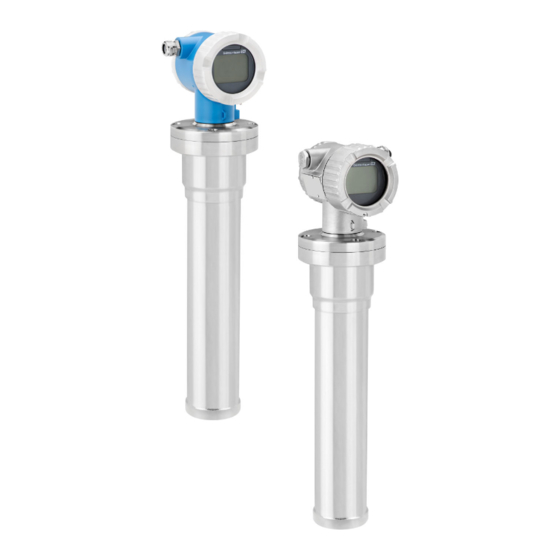
Compact transmitter for non-contact measurement
through vessel walls
Application
• Level, interface, density, concentration and point level measurement
• Measurement in liquids, solids, suspensions or sludges
• Use under extreme process conditions
• All kinds of process vessels
Advantages
• Compact transmitter with loop-powered two-wire technology
• Multifunctional compact transmitter for all measuring tasks: level, interface,
density, concentration and point level
• SIL2 approval according to IEC 61508 and SIL 3 for all measurement tasks with
homogeneous or diverse redundancy
• Heartbeat Technology to verify the correct functioning of the measuring device
within specifications without interrupting the process
• Optimum adjustment to the respective applications and measuring ranges via a
variety of detector materials
• Bluetooth® wireless technology for easy commissioning, operation and
maintenance via the free iOS / Android SmartBlue app
• Use of Gamma Modulator FHG65 for the reliable suppression of interference
radiation irrespective of the isotope
Solutions
Services
Advertisement
Table of Contents

Related Manuals for Endress+Hauser Gammapilot FMG50


Summary of Contents for Endress+Hauser Gammapilot FMG50
- Page 1 Products Solutions Services TI01462F/00/EN/02.20 71472785 2020-03-30 Technical Information Gammapilot FMG50 Radiometric measurement Compact transmitter for non-contact measurement through vessel walls Application • Level, interface, density, concentration and point level measurement • Measurement in liquids, solids, suspensions or sludges • Use under extreme process conditions •...
-
Page 2: Table Of Contents
Gammapilot FMG50 Table of contents About this document ......Installation conditions for point level detection ..27 Installation conditions for density measurement . - Page 3 Gammapilot FMG50 Clamping device for density measurement FHG51 ..45 Process indicator RIA15 ......46 Supplementary documentation for Gammapilot FMG50 .
-
Page 4: About This Document
Android, Google Play and the Google Play logo are trademarks of Google Inc. Bluetooth® The Bluetooth® word mark and logos are registered trademarks owned by the Bluetooth SIG, Inc. and any use of such marks by Endress+Hauser is under license. Other trademarks and trade names are those of their respective owners. Endress+Hauser... -
Page 5: Function And System Design
Gammapilot FMG50 Function and system design Application and advantages Application • Level, interface, density, concentration and point level measurement • Measurement in liquids, solids, suspensions or sludges • Use in extreme process conditions: high pressure, high temperature, corrosion, abrasion, viscosity, toxicity •... -
Page 6: Measuring Principle
In this case, the level of the medium in the vessel is at the set limit. The Gammapilot FMG50 indicates the uncovered state (no medium in the radiation path) with 0% and the covered state (radiation path filled with medium) with 100%. - Page 7 The density unit can be selected from a menu. The density signal of the Gammapilot FMG50 can be combined with the signal of a volume flowmeter, e.g. Promag 55S, and the mass flow can be calculated from these two signals.
-
Page 8: Measuring System
Bulk solids applications on conveyor belts and conveyor screws. The source container is positioned above the conveyor belt and the Gammapilot FMG50 below the conveyor belt. The radiation is attenuated by the medium on the conveyor belt. The intensity of the radiation received is proportional to the density of the medium. -
Page 9: Signal Analysis
The Gammapilot FMG50 is available with NaI (Tl) crystals or with PVT scintillators of different lengths, ensuring that it can be optimally adapted to each individual application. - Page 10 The measured values of up to four samples of known density can be stored in the Gammapilot FMG50 and used for the calibration of density measurements. The Gammapilot FMG50 calculates the absorption coefficient µ and the linearization curve automatically from these values. It then uses these parameters to calculate the density from the pulse rate.
- Page 11 Concentration Concentration measurement with radiating media The Gammapilot FMG50 calculates the concentration of the medium from the intensity of the radiation that is emitted by the medium itself. A source container and radiation source are not needed for the measurement...
- Page 12 Measured value Measurement of mass flow (liquids) The density signal determined by the Gammapilot FMG50 is transmitted to the Promag 55S. The Promag 55S measures the volume flow; the Promag can determine a mass flow in connection with the calculated density value.
-
Page 13: System Integration
Excess radiation: In the event of excess radiation, the Gammapilot FMG50 automatically switches off the evaluation of the radiation. The device checks the radiation regularly. As soon as the Gammapilot FMG50 establishes that the radiation has normalized or no more radiation is detected, it resumes normal operation. -
Page 14: Input
A0039186 Input Measured variable The Gammapilot FMG50 measures the pulse rate (number of pulses per second). This rate is proportional to the intensity of radiation at the detector. The Gammapilot M calculates the measured value from this rate: • Point level (0% = "radiation path free"; 100% = "radiation path covered") •... -
Page 15: Measuring Range
In the case of level measurement, the measuring range typically depends on the height of the vessel. To cover the entire measuring range, a scintillator is used that is longer than the measuring range. Several Gammapilot FMG50 units can be used for measuring ranges >3 m (9.84 ft). A0037672 Gammapilot FMG50 Max. - Page 16 Gammapilot FMG50 A0036646 Gammapilot FMG50 Density measurement In the case of density measurement, the density measuring range is defined by the minimum and maximum density of the measured medium. A0036645 Gammapilot FMG50 Interface measurement In the case of interface measurement, the measuring range is determined by the possible position of an interface.
-
Page 17: Output
Gammapilot FMG50 Output Output signal 4 to 20 mA with HART protocol The current output offers a choice of three different operating modes: • 4.0 to 20.5 mA • NAMUR NE043: 3.8 to 20.5 mA • US mode: 3.9 to 20.8 mA... -
Page 18: Terminal Assignment
Gammapilot FMG50 A0028908 3 Block diagram of HART connection Device with HART communication HART resistor Power supply The HART communication resistor of 250 Ω in the signal line is always necessary in the case of a low-impedance power supply. -
Page 19: Potential Equalization
Gammapilot FMG50 • NPT1/2 thread, IP66/68 NEMA Type 4X/6P • M12 plug, IP66/68 NEMA Type 4X/6P • HAN7D plug, 90 deg. IP65 NEMA Type 4x Connecting cables should be routed away from the housing from below to prevent moisture from penetrating the connection compartment. Otherwise, a drip loop should be provided or a weather protection cover should be used. - Page 20 Gammapilot FMG50 Connection of devices with Harting plug Han7D – + – Han7D – A0019990 Electrical connection for devices with Harting plug Han7D View of the plug-in connection on the device Material: CuZn, contacts for plug-in jack and connector are gold-plated...
-
Page 21: Fmg50 With Ria15
Alternatively available as an accessory, for details see Technical Information TI01043K and Operating Instructions BA01170K CAUTION ‣ Pay attention to the Safety Instructions (XAs) when using the Gammapilot FMG50 with the remote indicator RIA15 in hazardous environments: • XA01028R • XA01464K •... - Page 22 Gammapilot FMG50 Connection of the HART device and RIA15 with backlighting A0019568 6 Block diagram of HART device with RIA15 process indicator with light Device with HART communication Power supply HART resistor FMG50, RIA15 with installed HART communication resistor module The HART communication module for installation in the RIA15 can be ordered together with the device.
-
Page 23: Wiring
Wiring examples for point The output signal is linear between free and covered adjustment (e.g. 4 to 20 mA) and can be evaluated in the control system. If a relay output is needed, the following Endress+Hauser process level detection transmitters can be used: •... -
Page 24: Post-Connection Check
ATEX II (1) G [Ex ia] IIC, ATEX II (1) D [Ex ia] IIIC for RMA42 XA00095R SIL applications for Gammapilot in connection with RMA42 The Gammapilot FMG50 meets the requirements of SIL2/3 as per IEC 61508, see: FY01007F The RMA42 meets SIL2 as per IEC 61508:2010 (Edition 2.0), see the Functional Safety Manual:... -
Page 25: Performance Characteristics/Stability
Gammapilot FMG50 WARNING ‣ Only operate the device with the covers closed Performance characteristics/stability Dead time, time constant, Presentation of the dead time, time constant and settling time as per DIN EN 61298-2 settling time 100 % 63 % A0042012... -
Page 26: Measured Value Resolution
Gammapilot FMG50 Measured value resolution 1 µA Influence of ambient NaI (Tl) crystal • Temperature range: –40 to +50 °C (–40 to +122 °F) temperature Influence of ambient temperature: +- 0.1% • Temperature range: –40 to +80 °C (–40 to +176 °F) Ambient temperature effect: –0.1 to +0.7 %... -
Page 27: Installation Conditions
Gammapilot FMG50. Observe the measuring range marks of the device. • The source container and the Gammapilot FMG50 should be mounted as close to the vessel as possible. Any access to the beam must be blocked to ensure that it is not possible to reach into this area. -
Page 28: Installation Conditions For Density Measurement
Measuring system arrangement The arrangement of the source container and the Gammapilot FMG50 depends on the pipe diameter (or the radiated length) and the density measuring range. These two parameters determine the measuring effect (relative change in the pulse rate). The longer the radiated length, the greater the measuring effect. -
Page 29: Installation Conditions For Interface Measurement
When a radiation source is used in an immersion tube, the radiation can be aligned with the measuring range of the Gammapilot FMG50 using a collimator on the immersion tube. -
Page 30: Installation Conditions For Density Profile Measurement (Dps)
Measuring system arrangement The arrangement of the source container and the Gammapilot FMG50 depends on the pipe diameter (or the radiated length) and the density measuring range. These two parameters determine the measuring effect (relative change in the pulse rate). The longer the radiated length, the greater the measuring effect. -
Page 31: Installation Conditions For Concentration Measurement With Radiating Media
Measurement of mass flow (liquids) flow measurement The density signal determined by the Gammapilot FMG50 is transmitted to the Promag 55S. The Promag 55S measures the volume flow; the Promag can determine a mass flow in connection with the calculated density value. -
Page 32: Environment
Bulk solids applications on conveyor belts and conveyor screws. The source container is positioned above the conveyor belt and the Gammapilot FMG50 below the conveyor belt. The radiation is attenuated by the medium on the conveyor belt. The intensity of the radiation received is proportional to the density of the medium. -
Page 33: Shock Resistance
Gammapilot FMG50 Shock resistance IEC 60068-2-27; test Ea; 30 g, 18 ms, 3 shocks/direction/axis Electromagnetic Electromagnetic compatibility in accordance with all of the relevant requirements outlined in the EN 61326 series and NAMUR Recommendation EMC (NE 21). For details, please refer to the... -
Page 34: Materials
The weight data refer to the stainless steel housing versions. The aluminum housing versions are 2.5 kg (5.51 lb) lighter. The additional weight for small parts is: 1 kg (2.20 lb) Materials Two different housing versions are available for the Gammapilot FMG50. Endress+Hauser... -
Page 35: Measuring Range Marks
FieldCare and DeviceCare are Endress+Hauser asset management tools based on FDT technology. With FieldCare, you can configure all Endress+Hauser devices as well as devices from other manufacturers that support the FDT standard. Hardware and software requirements can be found on the Internet at: www.de.endress.com ->... - Page 36 A0038834 11 DeviceCare/FieldCare via service interface (CDI) Computer with DeviceCare/FieldCare operating tool Commubox FXA291 Service interface (CDI) of the measuring device (= Endress+Hauser Common Data Interface) Via Bluetooth® wireless technology (optional) A0038833 12 Operation via SmartBlue (app) Transmitter power supply unit...
-
Page 37: Local Operation
15 Block diagram FMG50, with RIA15 process indicator Gammapilot FMG50 Power supply HART resistor The Gammapilot FMG50 can be configured for the basic setup using the RIA15 indicator For details refer to TI01043K BA01170K Certificates and approvals The availability of approvals and certificates can be called up daily via the Product Configurator. -
Page 38: Functional Safety
-> Select product -> Configure CE mark The measuring system meets the legal requirements of the EU Directives. Endress+Hauser confirms that the device has been successfully tested by applying the CE mark. Approval for EAC is pending Overfill prevention... -
Page 39: Application Packages
Gammapilot FMG50 Application packages Detailed description SD02414F SIL wizard Availability Available for the following versions of feature 590 "Additional approval": LA: SIL Function • Wizard for the proof test which must be performed at regular intervals in the following applications: SIL (IEC61508/IEC61511) •... -
Page 40: Heartbeat Verification
Gammapilot FMG50 Heartbeat Verification Availability Available for the following versions of feature 540 "Application package": EH: Heartbeat Verification + Monitoring Device functionality checked on demand • Verification of the correct functioning of the measuring device within specifications. • The verification result provides information about the condition of the device: Passed or Failed. -
Page 41: Heartbeat Monitoring
Gammapilot FMG50 Heartbeat Monitoring Availability Available for the following versions of feature 540 "Application package": EH: Heartbeat Verification + Monitoring Function In addition to the verification parameters, the corresponding parameter values are also logged. Advantages • Supports the scheduling of maintenance work, and thereby helps ensure plant availability. -
Page 42: Mounting Device (For Level And Point Level Measurement)
Gammapilot FMG50 Mounting device (for level Mounting the retaining bracket and point level Reference dimension A is used to define the mounting location of the retaining bracket depending measurement) on the measuring range. A0040283 16 A defines the distance between the device flange and the start of the measuring range. Distance A depends on the material of the scintillator (PVT or Nal). - Page 43 Gammapilot FMG50 Dimensions of mounting clamps 6 Nm A0042084 18 Dimensions of mounting clamp Distance A • For electronics pipe: 210 mm (8.27 in) • For detector pipe: 198 mm (7.8 in) CAUTION Max. torque for the screws of the retainers: ‣...
- Page 44 Gammapilot FMG50 Dimensions of retaining bracket 88 (3.46) 30 (1.18) 175 (6.89) 135 (5.31) 153 (6.02) A0040030 21 Retaining bracket Endress+Hauser...
- Page 45 The retainers provided can be used for FMG50 (see Figure C). ‣ To prevent damage to the detector pipe of the Gammapilot FMG50, the maximum torque that can be applied to tighten the retainer screws is 6 Nm (4.42 lbf ft).
- Page 46 For an overview of the scope of the associated Technical Documentation, refer to the following: • W@M Device Viewer (www.endress.com/deviceviewer): Enter the serial number from nameplate • Endress+Hauser Operations App: Enter the serial number from the nameplate or scan the 2D matrix code (QR code) on the nameplate Fields of activity...
- Page 47 Gammapilot FMG50 Description of Device GP01141F Functions Functional safety Functional Safety Manual for Gammapilot FMG50 FY01007F Clamping device for density SD02533F measurement SD02534F Supplementary documentation for radiation source, source containers and modulator Radiation source FSG60, • Technical Information for radiation source FSG60/FSG61 FSG61 •...
- Page 48 *71472785* 71472785 www.addresses.endress.com...