Table of Contents
Advertisement
Available languages
Available languages
Quick Links
IB517061ML
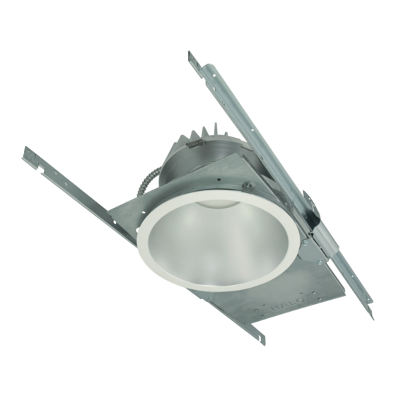
Installation Instructions – HC8R/HC812R Recessed LED
Retrofit
Instructions d'installation – HC8R/HC812R DEL Retrofit
encastré
Instrucciones de instalación – de las luminarias LED
adaptadoras, empotradas y de uso HC8R/HC812R
Risk of Fire, Electrical Shock, Cuts or other Casualty Hazards- Installation and maintenance of this
product must be performed by a qualified electrician. This product must be installed in accordance
with the applicable installation code by a person familiar with the construction and operation of
the product and hazards involved.
Risk of Fire and Electric Shock- Make certain power is OFF before starting installation or
attempting any maintenance. Disconnect power at fuse or circuit breaker.
Risk of Fire- Minimum 90°C supply conductors.
Risk of Burn- Disconnect power and allow fixture to cool before handling or servicing.
Risk of Personal Injury- Due to sharp edges, handle with care.
Failure to comply with these instructions may result in death, serious bodily injury and property
damage.
DISCLAIMER OF LIABILITY: Cooper Lighting Solutions assumes no liability for damages or losses of any kind
that may arise from the improper, careless, or negligent installation, handling or use of this product.
IMPORTANT: Read carefully before installing fixture. Retain for future reference.
NOTICE: Fixture may become damaged and/or unstable if not installed properly.
Note: Specifications and dimensions subject to change without notice.
Note: This fixture should be supported by main runners or other structure that is capable of supporting fixture
weight of 40 Ibs.
ATTENTION Receiving Department: Note actual fixture description of any shortage or noticeable damage on
delivery receipt. File claim for common carrier (LTL) directly with carrier. Claims for concealed damage must be
filed within 15 days of delivery. All damaged material, complete with original packing must be retained.
HALO Commercial
WARNING
Brand Logo
reversed out of
black
INS #
INS #
Advertisement
Table of Contents

Related Manuals for Cooper HALO HC8R


Summary of Contents for Cooper HALO HC8R
- Page 1 Failure to comply with these instructions may result in death, serious bodily injury and property damage. DISCLAIMER OF LIABILITY: Cooper Lighting Solutions assumes no liability for damages or losses of any kind that may arise from the improper, careless, or negligent installation, handling or use of this product.
- Page 2 (see Wiring Diagrams). 10. Replace ballast/junction box cover to completely close junction box. COOPER LIGHTING SOLUTIONS IB517061ML Installation instructions...
- Page 3 Feed supply wires from retrofit driver assembly through Figure 15. Figure 16. knock-out that was removed in junction box and insert snap-in connector into junction box (Figure 18). Figure 17. Figure 18. COOPER LIGHTING SOLUTIONS IB517061ML Installation instructions...
- Page 4 Adapter Band Ring (if present) rest flush on ceiling. Figure 27. Figure 28. Retrofit Ring Assembly may need to be rotated to avoid interference (Figure 30). Figure 29. Figure 30. COOPER LIGHTING SOLUTIONS IB517061ML Installation instructions...
- Page 5 90° angle with the fixed base of the safety bracket (Figure 34). Side Clips Safety Brackets Figure 36. Figure 33. COOPER LIGHTING SOLUTIONS IB517061ML Installation instructions...
-
Page 6: Electrical Connection
Connect supply lead wires to junction box lead wires (line, neutral and ground) in the fixture using the provided connectors. (Figure 43). Be careful not to leave any bare conductors outside of the connectors. Figure 39. COOPER LIGHTING SOLUTIONS IB517061ML Installation instructions... -
Page 7: Driver Replacement
A purchaser’s receipt or other proof of date of original purchase acceptable to Cooper The driver should be replaced by a qualified electrician. -
Page 8: Installation
La désobéissance aux instructions suivantes représente un risque de blessures graves ou mortelles et de dommages matériels. EXONÉRATION DE RESPONSABILITÉ : Cooper Lighting Solutions n’assume aucune responsabilité pour les dommages ou pertes de toute nature pouvant découler d’une installation inappropriée, imprudente ou négligente et d’une mauvaise manipulation ou utilisation de ce produit. - Page 9 Éloignez le circuit de sortie de l’ouverture du plafond ou du boîtier en le laissant tourné vers le haut (Figure 11). Laissez pendre les conduits flexibles du circuit de sortie par l’ouverture du plafond ou du boîtier. Figure 11. Figure 12. COOPER LIGHTING SOLUTIONS IB517061ML Instructions d’installation...
- Page 10 (Figure 20). Retirez une entrée défonçable d'un diamètre de 7/8 po (conduit d'une taille de 1/2 po) dans la boîte de jonction, Figure 22. Figure 21. si possible sur le dessus de cette dernière. COOPER LIGHTING SOLUTIONS IB517061ML Instructions d’installation...
- Page 11 Pour éviter un déplacement dans l’ouverture du boîtier/ plafond, utilisez un tournevis à tête plate pour dégager les 4 languettes de centrage sur l’assemblage d’anneaux Retrofit (Figure 32.). Figure 32. Figure 23. Figure 24. COOPER LIGHTING SOLUTIONS IB517061ML Instructions d’installation...
- Page 12 Figure 36. Hauteur minimale de 5-1/2 po requise pour l’installation Assurez-vous que le câblage, le conduit et le boîtier de douille soient si possible déplacés vers le côté. Fixations de sécurité Figure 37. Figure 33. COOPER LIGHTING SOLUTIONS IB517061ML Instructions d’installation...
-
Page 13: Raccordement Électrique
à l’installation ou à l’entretien de ce luminaire. Le pilote doit être remplacé par un électricien qualifié. ● Le pilote peut être remplacé à partir du dessus ou du ● dessous du plafond. COOPER LIGHTING SOLUTIONS IB517061ML Instructions d’installation... - Page 14 Cooper Lighting Solutions garantit à ses clients, pendant une période Rattachez le nouvel assemblage du pilote et du de cinq ans à compter de la date d’achat, que ses produits Cooper couvercle de la boîte de jonction. Lighting Solutions sont exempts de tout défaut de matériaux et de fabrication.
-
Page 15: Instalación
El incumplimiento de estas instrucciones puede ocasionar la muerte, lesiones corporales graves y daños a la propiedad. RENUNCIA DE RESPONSABILIDAD: Cooper Lighting Solutions no asume ninguna responsabilidad por daños o pérdidas de ningún tipo que puedan surgir por la instalación, manipulación o uso inadecuado, descuidado o negligente de este producto. - Page 16 Coloque la unidad del controlador adaptador a través de la abertura del techo/alojamiento (Figura 10). Coloque la unidad del controlador adaptador lejos de la abertura del techo/alojamiento y ponga el controlador Figura 11. Figura 12. hacia arriba (Figura 11). COOPER LIGHTING SOLUTIONS IB517061ML Instrucciones de instalación...
- Page 17 Para los alojamientos de luminarias incandescentes: Extraiga el reflector/la moldura y la lámpara existentes (Figura 19). Ajuste el soporte del portacasquillo en su posición máxima. Figura 22. Figura 21. COOPER LIGHTING SOLUTIONS IB517061ML Instrucciones de instalación...
- Page 18 2” (50,80 mm). Para los grosores de techo o Figura 31. alojamiento de entre 0,5” (12,70 mm) y 1” (25,40 mm), los muelles de montaje deben moverse a la posición inferior (Figura 31). COOPER LIGHTING SOLUTIONS IB517061ML Instrucciones de instalación...
- Page 19 Ganchos techo (Figura 41). laterales 10. Vuelva a conectar la alimentación después de finalizar la instalación. Figura 36. Figura 32. Soportes de seguridad Figura 37. Figura 33. COOPER LIGHTING SOLUTIONS IB517061ML Instrucciones de instalación...
-
Page 20: Conexión Eléctrica
Frote con una solución de detergente suave en un trapo suave y limpio para quitar las huellas digitales y l as manchas. Enjuague con agua limpia y seque con un trapo suave, limpio, seco y sin pelusas. Figura 43. COOPER LIGHTING SOLUTIONS IB517061ML Instrucciones de instalación... - Page 21 (Figura 40). Cooper Lighting Solutions estarán exentos por defectos en materiales y mano de obra. La obligación de Cooper Lighting Solutions bajo esta Extraiga el controlador y la unidad de la cubierta de la garantía queda expresamente limitada a la provisión de los productos caja de derivación.
- Page 22 • Cet appareil est conforme à la norme ISED ICES Canada ICES-005 (B) / NMB-005 (B). Cooper Lighting Solutions 1121 Highway 74 South Peachtree City, GA 30269 P: 770-486-4800 Cooper Lighting Solutions is a www.cooperlighting.com registered trademark. All trademarks are property Canada Sales of their respective owners.