Table of Contents
Advertisement
Quick Links
Identification - Instructions
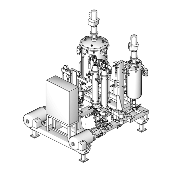
Aerobotix RC50
For dispensing controlled ratio shots of resin and isocyanate in Class 1, Division 1,
Group D atmospheres.
SN8023
3000 psi (21 MPa, 206 bar) Maximum Fluid Working Pressure
80 psi (550 kPa, 5.5 bar) Maximum Air Inlet Pressure
Important Safety Instructions
Read all warnings and instructions in this manual
and all supplied manuals. Save these instruc-
tions. See Related Manuals on page 3.
Main Control Panel, Module Applicator Group, and
Tempered Water Units Not Shown
313813A
ti14337a
Advertisement
Table of Contents
Troubleshooting

Related Manuals for Graco Aerobotix RC50


Summary of Contents for Graco Aerobotix RC50
- Page 1 Identification - Instructions Aerobotix RC50 313813A For dispensing controlled ratio shots of resin and isocyanate in Class 1, Division 1, Group D atmospheres. SN8023 3000 psi (21 MPa, 206 bar) Maximum Fluid Working Pressure 80 psi (550 kPa, 5.5 bar) Maximum Air Inlet Pressure...
-
Page 2: Table Of Contents
Settings ........45 Graco Manuals ......3 Temperature Control . -
Page 3: Related Manuals
Related Manuals Related Manuals Graco Manuals These manuals can be found at www.graco.com. Sub-Component Manuals Relates Manual No. to Part Description U80756 Assembly Drawings Manual 309475 234269 High Pressure Fluid Regulators Instructions and Parts 309524 245864 High Pressure Fluid Heater VISCON HP... -
Page 4: Warnings
Warnings Warnings For complete warnings, see supplied manuals. See Related Manuals on page 3. The following warnings are for the setup, use, grounding, maintenance, and repair of this equipment. The exclama- tion point symbol alerts you to a general warning and the hazard symbol refers to procedure-specific risk. Refer back to these warnings. - Page 5 Warnings WARNING INTRINSIC SAFETY Intrinsically safe equipment that is installed improperly or connected to non-intrinsically safe equipment will create a hazardous condition and can cause fire, explosion, or electric shock. Follow local regula- tions and the following safety requirements. • Be sure your installation complies with national, state, and local codes for the installation of electrical apparatus in a Class I, Division 1, Group D Hazardous Location, including all of the local safety fire codes, NFPA 33, NEC 500 and 516, and OSHA 1910.107.
- Page 6 Warnings WARNING EQUIPMENT MISUSE HAZARD Misuse can cause death or serious injury. • Do not operate the unit when fatigued or under the influence of drugs or alcohol. • Do not exceed the maximum working pressure or temperature rating of the lowest rated system component.
-
Page 7: Isocyanate Hazard
Isocyanate Hazard Isocyanate Hazard • Keep the ISO lube pump reservoir (if installed) filled with Graco Throat Seal Liquid (TSL), Part 206995. The lubricant creates a barrier between the ISO and the atmosphere. • Use moisture-proof hoses specifically designed for Spraying materials containing isocyanates creates ISO, such as those supplied with your system. -
Page 8: Component Identification
Component Identification Component Identification NOTE: See print U50166 for Module Applicator Group identification. See Assembly Drawings manual U80756 for further Graco-component identification. See non-Graco component manuals for further non-Graco component identification. POLY Side ti14337a ISO Side Key: AA Heat Exchangers... - Page 9 Component Identification ISO Side ti14338a POLY Side Key: AJ Poly Tank Agitator AK Poly Tank AL Iso Tank AM Iso Filter AN Iso Heater AP Iso Tank Agitator . 2: RC50 Base - Rear View 313813A...
- Page 10 Component Identification DF 1 Replacement Danger and Warning labels, tags and cards are available at no cost. Approved for Class 1, Division 1, Group D atmospheres. UL508A approved. Key: DA Intrinsically Safe Barrier DE Main Disconnect Switch DB Main Power On Light DF Warning Labels DC Control Power On Button DG Main Control Panel...
-
Page 11: Installation
Installation Installation Main Control Panel: Install in the non-hazardous area. RC50 Base: Install according to requirements for Intrin- sically Safe Installation (F . 4). General Info Remote Tempered Water Units: Install in the non-haz- Be sure all accessories are adequately sized and pres- ardous area. - Page 12 Installation NON-HAZARDOUS HAZARDOUS (CLASSIFIED) LOCATION LOCATION ONLY CLASS I, DIV I, GROUP D POLY Tempered Agitator Agitator Heater Water Unit POLY Tempered Water Unit Robot Control Cabinet POLY Metering Metering Heater Pump Pump Main Control Panel Machine Safety Frame Barrier Panel All conduits must be rigid metal conduit Intrinsically...
-
Page 13: Electrical Requirements
Installation Electrical Requirements All electrical wiring must be completed by a qualified electrician and comply with all local codes and regu- lations. Enclose all cables routed in high traffic areas in con- duit to prevent damage from materials, solvent, and traffic. -
Page 14: Grounding
Ground the system as described here and in the individ- ual component manuals. A ground wire and clamp, part number 223547, is available from Graco. Main Control Panel Connect a ground wire to a true earth ground. Machine Junction Box Connect a ground wire to a true earth ground. - Page 15 Installation NON-HAZARDOUS LOCATION ONLY HAZARDOUS (CLASSIFIED) LOCATION CLASS I, DIV I, GROUP D Main Control Panel RC50 Base Tempered Water Unit Poly Tempered Water Unit Module Applicator Group NOTE: Assemblies (not all items shown) not shown to scale ti14339a NOTE: See U80638 control schematic. .
-
Page 16: Startup
Startup Startup 5. Turn on the control power by hitting the green push-button on the main panel. The button will be lit when control power is on. See F . 3 on page 10 for more information. Before turning on the pump motors, make sure See startup instructions and related warnings in sup- there is sufficient chemical in both day tanks and plied manuals. -
Page 17: Operation
Operation Operation Human Machine Interface (HMI) Screens When main power is turned on, the HMI will automatically turn on. Main Menu Screen Screen is only accessible when logged in as one of the “Maintenance” usernames. If not logged in this button will not be accessible. Shown on all screens. - Page 18 Scaling screen. To gain access to the Scaling screen, the user must log in as a “Maintenance” user (Password 10). The “Factory” user name is reserved for Graco factory personnel to set initial parameters on the machine. Setting the System Clock To adjust the system clock, first turn on main power and then control power.
- Page 19 Operation Status Screen In the figure below, only the Iso side has been labeled. The items on the Poly side are the same as those on the Iso side. Status is indicated by a red background and the word “OFF” or a green background and the word “ON” The path the fluid follows is indicated by these lines.
- Page 20 Operation Manual, Automatic Modes With control power on, either of these modes can be selected. When a certain mode is selected, the related button will turn green. System Status Indicators The status of all system conditions is shown. This includes various temperatures and pressures through- out the system.
- Page 21 Operation Manual Control Screen Only active when service mode has been selected. Key: DA Visual Indicators: PLC Inputs DB Visual Indicators: PLC Outputs DC Temperature/Flow Information DD Visual Indicator of Active Gun DE Service Mode Control Service Mode Automatic Mode Status Service mode allows the operator to open the gun for The Automatic Mode Status section is a visual status service under no load.
- Page 22 Operation Machine Control Screen Key: DA Low Level Bypass On/Off Control DE Night Mode On/Off DB Gun Enable DF Flow Information DD Iso/Poly Agitator Motor Start/Stop Motors Start and Stop Buttons These buttons control whether a specific motor is run- ning and the current status of each motor will be dis- played below each set of buttons.
- Page 23 Operation Tank Control Screen . 10 Key: EA Auto-Fill On/Off EG Fill Delay EF Fail to Fill Alarm Delay Iso, Poly Temperature Control The Temperature Control Screen is accessible by press- ing the Temperature Control button. See Temperature Control Screen on page 24. 313813A...
- Page 24 Operation Temperature Control Screen Press the Temp Gain Setup button to change the temperature gains. . 11 Key: FA Ideal Temperature Setpoint FD Actual Temperatures FB High Temperature Alarm Setpoint FE Temperature Log Access FC Low Temperature Alarm Setpoint FF Temperature Gain Access Heat Exchange and Supply Heater Temperature Control These buttons are used to turn temperature control on...
- Page 25 Operation Pour Time Editor Screen . 12 Key: FA Preset Pour Timers, seconds duration FD Previous Group FB Press Interface Automatic Mode Pour Time FE Next Group FC First Group FF Last Group The Pour Time Editor screen allows entry of a pour time preset for each of the 99 available channels.
- Page 26 Operation Setup Screen . 13 Key: GA Pressure Build Time GD Cleanout Delay setting GB Night Mode On/Off Time GE Cleanout Extend Time setting GC Iso, Poly Specify Gravity GF Pressure Hold Time See Settings section on page 45 for more information. Night Mode On/Off Time See Night Mode Operation on page 43 for more infor- mation.
- Page 27 Operation Flow Control Screen This screen is accessible from the Flow Control screen but only if logged in as one of the “Mainte- nance” usernames. . 14 Key: HA Manual Flow Control HL Automatic Mode Ratio Setpoint (Iso divided by Poly) HB Automatic Flow Control HM Automatic Mode Total Flow Setpoint (grams per second) HD Flow Ratio Warning/Shutdown Tolerance (percent)
- Page 28 Operation Manual Flow Control Enables use of the Manual Mode Motor Percent Set- points. When in Manual mode, motor speed remains constant. Automatic Flow Control Enables use of the Automatic Mode Setpoints and machine will continually adjust motor speeds to meet setpoints.
- Page 29 Operation Scaling Screen This screen is only accessible when logged in as one of the “Maintenance” usernames. . 15: This screen is for qualified technicians only and is password protected. Key: JA Current K Factor Value JG Flowrate Filter On/Off JB Test Shot Actual Weight (grams) JH Last Shot Data JC Iso Calibration Shot start button...
- Page 30 Operation Temperature Log Screen This screen is accessible from the Scaling screen. . 16: This screen is for qualified technicians only and is password protected. Key: KA Up Scale KE Home KB Down Scale KF End KC Pen KG Pause KD Move Left KH Move Right 313813A...
- Page 31 Operation Alarm History and Alarm Status Screens See Troubleshooting section on page 57 for Alarm screens details. 313813A...
-
Page 32: Tanks
Operation Tanks ti14338a1 . 17 Key: MA Tank MG Water Separator MB Pressure Relief and Manual Vent Valve MH Tank Fluid Level Sight Gauge MC Pressure Gauge and Regulator MJ Tank Outlet Ball Valve MD Level Sensor MK Day Tank Incoming Air Valve ME Metering Pump Inlet Filter ML Tank Drain Ball Valve MF Tank Outlet to Pump Ball Valve... - Page 33 Operation Metering Pump Inlet Filter NOTICE Relieving tank pressure may introduce moist air into NOTICE the system causing crystallization and damage to the The metering pump inlet filter prevents particulate mat- machine. ter from damaging the precision metering pumps. The filter element is a basket type and should it become The pumps must never be run dry.
-
Page 34: Pumpline
Operation Pumpline ti14338a1 . 18 Key: NA Pump Turn-Dial NE Pressure Switches NB Metering Pump NF Relief Valve NC Metering Pump Air Purge Valve NG Pressure Transducer ND Metering Pump Motor NH Inlet Pressure Gauge Both pumps are protected on the inlet side by a basket filter and a low-pressure switch. -
Page 35: Temperature Control
Operation Temperature Control ti14337a1 . 19 PA Heater PD Supplied Water Outlet PB Heat Exchanger PE Thermocouple PC Supplied Water Inlet Heat Exchanger Heater The heat exchanger (PB) cools the chemical in the The heater (PA) heats the material to the desired tem- pump inlet line prior to reaching the pump. -
Page 36: Other Components
Operation Other Components ti14338a1 . 20 Key: QA Chemical Line Pressure Gauge QC Air Manifold QB Flow Meter Circulation Valve A pneumatically operated Circulation Valve (remotely mounted) allows low pressure operation at startup and between shots. It transfers flow from the outlet of the flow meter, through the dispense guns so that flow bypasses the back-pressure regulator. -
Page 37: Variable Frequency Drive
Operation Variable Frequency Drive The variable frequency drive enables control of the metering pump motor rpm as well as advanced flow control from the HMI. See Adjusting Metering Pump Motor RPM on page 48 and Calibrating Machine-Calculated Mass Flow on page 50 for more information on Variable Frequency Drive operation. -
Page 38: Setup
Prior to installing the machine, check for any damage that may have occurred during transit. If any damage is found, notify Graco immediately. The machine is to be installed on a flat surface in an area that permits easy access to all areas of the machine for maintenance and operation. -
Page 39: Dispense Gun Hoses
Setup Dispense Gun Hoses ti14338a1 . 21: Dispense Gun Hose Setup Key: SA Poly Return to Tank SC Iso Pressure SB Poly Pressure SD Iso Return to Tank 313813A... -
Page 40: Optional Robot Interface
Setup Optional Robot Interface The following information is the typical sequence of operation for a Robot Dispense Command. 1. The Robot System is placed in the proper state for automatic cycle. 2. The RC System is placed in the proper state for automatic cycle (remote mode). -
Page 41: New Machine Maintenance
New Machine Maintenance New Machine Maintenance Metering Pump Inlet Filter During the first week of operating a new machine, the fil- ter should be inspected every other day. If the element is dirty, clean it with solvent or replace it with a new one as required. -
Page 42: Pouring Operation
Pouring Operation Pouring Operation Low and High Pressure Beginning the Pour Circulation After both streams reach the required pour pressure and the preset pressure build time elapses, the MixHead is When the metering pump motors are first turned on, the commanded to open and the pour occurs. -
Page 43: Night Mode Operation
Night Mode Operation Night Mode Operation The following requirements must be met to start night NOTICE mode. Night mode enables machine operation when person- nel are not present. If the machine encounters a prob- • Main and Control power on lem during Night mode, such as a hose rupture or •... -
Page 44: Shutdown
Shutdown Shutdown Overnight/Weekend 10. Turn on main power and control power. 11. Run the system in manual mode for 45 minutes. If using Night Mode to circulate chemicals and maintain See Manual, Automatic Modes on page 20. chemical temperature, see the Night Mode Operation section on page 43. -
Page 45: Settings
Settings Settings Temperature Switch Pressures MAG drive .........170° F (76.7°C) Chemical Absolute High Temperature . - Page 46 Settings High Temperature Setpoint If the temperatures are not controlled to your desire with the gains set to the default settings of “100”, you may be The high temperature setpoint is the temperature at able to adjust the gains to make the machine work better which the high temperature alarm will be triggered to for your application.
-
Page 47: Pouring Settings
Settings To check initial heating time, once the chemicals have High Pressure Hold Time cooled to ambient temperature turn on the pumps and High Pressure Hold Time is set using the Setup screen, heaters. If it takes too long to heat up, either raise the see F . -
Page 48: Mixhead Settings
Settings Flow-Rate Display Filter When the preceding requirements are met: See F . 15 on page 29 for more information. 1. Select manual mode and high pressure override to put the machine into high-pressure circulation. MixHead Settings The pressure for the two chemical lines should be within 200 psi to avoid chemical crossover at the MixHead On/Off MixHead. -
Page 49: Flow Measurement Controls
Settings 3. Allow the day tank charge pressure to bleed to 5 psi 6. If necessary, balance the chemical line pressures by (0.034 MPa, 0.34 bar). slowly adjusting each orifice on the MixHead with a hex key until the pressure remains constant for at 4. - Page 50 Settings 1. Turn on the MixHead, Hydraulic Motor, and Metering Calibrating Machine-Calculated Mass Flow Pump motors. 2. Turn the metering pump dial all the way counter- clockwise to read zero on the dial. Avoid breathing of vapors and contact with Isocya- 3.
- Page 51 Settings Parts/Tools Required 12. Measure the weight of the clean, dry, and empty cal- ibration bucket in grams. Record this measurement • 5 Gallon Bucket to catch spilled material or tare the scale. • 5 Gallon Bucket to weigh dispensed material 13.
- Page 52 Settings Change Chemical Sides 21. Turn off all motors. 22. Turn the main panel power handle to the off position and lockout. 23. Relieve air pressure, hydraulic fluid pressure, and chemical line pressure. See Pressure Relief Pro- cedure on page 53. 24.
-
Page 53: Pressure Relief Procedure
Pressure Relief Procedure Pressure Relief Procedure Chemical Line Pressure Relief 1. Turn off and lockout main power. When the metering pump motors are turned off, all Before performing system maintenance, system pres- chemical line pressure is relieved except for the sure must be relieved. -
Page 54: Maintenance
Maintenance Maintenance Schedule Check/Replace Metering Pump Inlet Filter Procedure Frequency Purge Air from Metering Pump Daily before use Drain the Water Separator Daily Check Metering Pump Inlet Filter Weekly Check Tightness of all Clamps Monthly Always relieve day tank pressure and close the tank and Fittings bleed valve to prevent fluid flow to the metering pump inlet filter. -
Page 55: Check Tightness Of All Clamps And Fittings
Maintenance 7. Ensure that the element is properly seated in the Replace the PLC battery bowl and replace the cap. 8. Hand tighten the clamp. 9. Open the tank ball valve and check for leaks. This procedure requires entering the main panel 10. -
Page 56: Empty The Day Tank
Maintenance Empty the Day Tank See the day tank capacity in the table at the begin- ning of the Settings section on page 45. To avoid a potential mess, always prepare to collect up to the full capacity. 1. Turn the main power handle to the off position and lockout. -
Page 57: Troubleshooting
Troubleshooting Troubleshooting See the table at the beginning of the Settings section on page 45 for temperature and pressure alarm settings. NOTE: See non-Graco manuals for non-Graco compo- nent troubleshooting. Alarm Status Screen . 22 Key: RA Alarm Silence RC Reset Alarm Data... -
Page 58: Alarm History Screen
Troubleshooting Alarm History Screen Sort button. Push to sort by name or time of alarm. . 23 This screen stores all alarms that have been triggered. See the table at the beginning of the Settings section on page 45 for pressure and temperature switch settings. 313813A... -
Page 59: Alarms List
Troubleshooting Alarms List Iso, Poly Metering Pump Inlet Low-Pressure Alarm • This alarm is generated any time the inlet pressure at the metering pump drops below the setting of the Pouring Alarms inlet low-pressure switch. This alarm stops the If a pouring alarm has been triggered, and the cause is affected metering pump motor. - Page 60 Troubleshooting Temperature Alarms Poly/Iso Heater High Temperature • This alarm is triggered when the temperature reaches the heater high temperature switch setting. In this event, the heater will need to cool to the heater switch “on-temperature” setting. Iso/Poly Low/High Temperature •...
-
Page 61: Troubleshooting Chart
Troubleshooting Troubleshooting Chart Automatic Action Fault taken by Machine Solution Iso, Poly Heater High Temp • Alarm banner Check high temperature set point • Yellow alarm light ON Check Power cube • Fault horn ON Allow heater to cool, reset limit switch ONE •... -
Page 62: Recommended Spare Parts
Recommended Spare Parts Recommended Spare Parts Qty on Rec. Qty One Part Description Machine Time Buy Tanks 6311-22 1/4" FPT Bleed Valve 6311-379 Air Pressure Regulator 1/4" FPT 94/0762/99 Air pressure Safety relief valve OP155-11 Check valve 6311-203 ADJ Relief Valve 1/4" FPT 6314-3 Gauge, 1/4 Bottom MT, 2.5"... - Page 63 Recommended Spare Parts Qty on Rec. Qty One Part Description Machine Time Buy RC Heaters (Part List for two Heater Assembly) 6690-7-136 Thermocouple Type -E 15300-30-1 Thermocouple Tube Ferrule 15300-30-2 Thermocouple Tube Nut 15300-30-3 Thermocouple Tube Body fitting 102124 Thermometer, Dial 223126 Sensor, Thermal Limit RC-50 Flow Meters (.1 to 7 gpm)
- Page 64 Recommended Spare Parts Qty on Rec. Qty One Part Description Machine Time Buy RC Electrical Console (continued) U70380 Module, Output, Analog, Current 6690-34-5 Relay, 16 Point Relay Output 6690-34-60 Module, Input, 32 PT 6690-34-59 Rack, PLC, 13 Slot, SLC 500 6690-34-220 Counter, HS 5-756-500NT8...
-
Page 65: Technical Data
Technical Data Technical Data Maximum Fluid Working Pressure ....3000 psi (20.6 MPa, 206 bar) Maximum Air Working Pressure ....100 psi (0.68, 6.8 bar) Maximum Fluid Temperature . -
Page 66: Graco Ohio Standard Warranty
With the exception of any special, extended, or limited warranty published by Graco, Graco will, for a period of twelve months from the date of sale, repair or replace any part of the equipment determined by Graco to be defective.