Table of Contents
Advertisement
Quick Links
TM
Table of Contents
Section Code
Section
1
1
1
1
1
1
1
1
1
1
Console Service Mode
1
1
Mechanical Procedures
2
3
Part Replacement
4
5
Brake Assembly
6
7
8
Data Cable in the Mast
9
Drive Belt and Flywheel Assembly
10
Drive Pulley (Crank Assembly)
11
Heart Rate Cable in the Mast
12
Pedals
13
Power Inlet
14
RPM Sensor (Speed Sensor)
15
Seat Rail Assembly
16
Servo Motor
17
18
Transport Wheels
Nautilus, Inc., www.NautilusInc.com, 5415 Centerpoint Parkway, Groveport, OH 43125 U.S.A. - Customer Service: North America (800) 605-3369, csnls@nautilus.com | outside U.S. www.nautilusinternational.com |
Printed in China | © 2022 Nautilus, Inc. | Schwinn and the Schwinn logo are trademarks owned or licensed by Nautilus, Inc., registered or otherwise protected by common law in the United States and other nations. |
ORIGINAL DOCUMENT - ENGLISH VERSION ONLY
8027965.020122.A
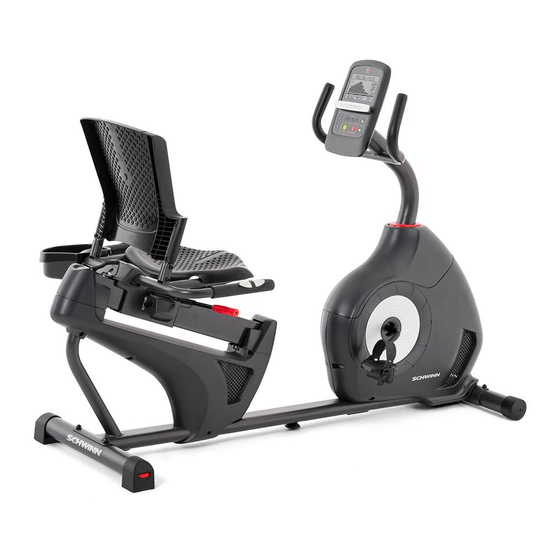
Schwinn
230 / 510R (Model Year 2020)
™
Recumbent Bike Service Manual
Page Number
10
11
12
18
24
30
36
38
41
45
53
60
64
67
73
78
83
89
94
1
2
3
3
4
5
6
6
7
8
9
Service Manual
8027921.020122.A
Advertisement
Table of Contents

Related Manuals for Schwinn 130/510U


Summary of Contents for Schwinn 130/510U
-
Page 1: Table Of Contents
Nautilus, Inc., www.NautilusInc.com, 5415 Centerpoint Parkway, Groveport, OH 43125 U.S.A. - Customer Service: North America (800) 605-3369, csnls@nautilus.com | outside U.S. www.nautilusinternational.com | Printed in China | © 2022 Nautilus, Inc. | Schwinn and the Schwinn logo are trademarks owned or licensed by Nautilus, Inc., registered or otherwise protected by common law in the United States and other nations. | ORIGINAL DOCUMENT - ENGLISH VERSION ONLY 8027965.020122.A... -
Page 2: Important Safety Instructions
Nautilus, Inc., www.NautilusInc.com, 5415 Centerpoint Parkway, Groveport, OH 43125 U.S.A. - Customer Service: North America (800) 605-3369, csnls@nautilus.com | outside U.S. www.nautilusinternational.com | Printed in China | © 2022 Nautilus, Inc. | Schwinn, Schwinn Toolbox and the Schwinn logo are trademarks owned or licensed by Nautilus, Inc., registered or otherwise protected by common law in the United States and other na- tions. -
Page 3: Safety Warning Labels And Serial Number
Safety Warning Labels and Serial Numbers WARNING! WARNING! • Injury or death is possible if • Keep hands • caution is not used while using and feet away. this machine. • • Keep children and pets away. • Read and follow all warnings on this machine. -
Page 4: Specifications
Specifications Maximum User Weight: 136 kg ( 300 lb ) Total Surface Area (footprint) of equipment: 11,423.8 cm 111.8 cm Machine Weight: 37 kg ( 81.57 lb ) (44 in) Power Requirements (AC Adapter): Input Voltage: 100 - 240V AC, 50/60Hz, 0.4A Output Voltage: 9VDC, 1.5A 162.5 cm... -
Page 5: Maintenance
Maintenance Read all maintenance instructions fully before you start any repair work. In some conditions, an assistant is necessary to do the necessary tasks. Equipment must be regularly examined for damage and repairs. The owner is responsible to make sure that regular maintenance is done. -
Page 6: Moving The Bike
Moving the Bike The machine may be moved by one or more persons depending on their physical abilities and capacities. Make sure that you and others are all physically fit and able to move the machine safely. Remove the power cord. Use the Transport Handle to carefully lift the machine onto the transport rollers. -
Page 7: Connectivity
Updates to Your Machine using the “Schwinn Toolbox™” App This fitness machine is equipped with Bluetooth connectivity and can be wirelessly updated with the “Schwinn Toolbox™” ® App. Once the App is installed on your device, the App will inform you of when there is an update to your machine. -
Page 8: Troubleshooting
Troubleshooting Condition/Problem Things to Check Solution No display/partial display/ Check electrical (wall) Make sure unit is plugged into a functioning wall outlet. unit will not turn on outlet Check connection at front Connection should be secure and undamaged. Replace of unit adapter or connection at unit if either are damaged. - Page 9 Condition/Problem Things to Check Solution Resistance does not Check data cable integrity All wires in cable should be intact. If any are visibly crimped or change (machine turns on cut, replace cable. and operates) Check data cable Be sure cable is connected securely and oriented properly. connections/orientation Reseat all connections.
-
Page 10: Maintenance Parts Exploded View
Maintenance Parts Exploded View Console Transport Wheel Console Cable, Lower Seat Back Stabilizer, Front Shroud, Right Seat Cover Heart Rate Cable, Lower Pedal, Right Water Bottle Holder Drive Pulley Power Connector Handlebar, Side Speed Sensor Magnet Shroud, Upper Seat Bottom Speed Sensor Shroud Cap Seat Adjustment Handle... -
Page 11: Replacement Procedure Skill Level
REPLACEMENT PROCEDURE SKILL LEVEL Level I : Low - very little mechanical knowledge or exposure. Level II : Intermediate - some experience with mechanical procedures Level III : Advanced - knowledgeable about mechanical procedures Disconnect all power to the machine before you service it. When disposing of old parts, obey the applicable local and provincial requirements. -
Page 12: Adjust The Belt Tension
ORIGINAL in China | © 2022 Nautilus, Inc. | Schwinn and the Schwinn logo are trademarks owned or licensed by Nautilus, Inc., registered or otherwise protected by common law in the United States and other nations. | DOCUMENT - ENGLISH VERSION ONLY Important Safety Instructions - Before servicing or using this equipment, obey the following warnings: This icon means a potentially hazardous situation which, if not avoided, could result in death or serious injury. - Page 13 Disconnect all power to the machine before you service it. Note: Your machine may not match the image. For reference only. 1. Loosen and remove the Pedals. Note: The Left Pedal is reverse-threaded. Orientation is based from a seated position on the bike. The Left Pedal has an “L”, the Right Pedal an “R”.
- Page 14 3. Flex the edges of the Upper Shroud to disengage the inside tabs from the Main Assembly, and slide it up the Console Mast. 4. Using a 6mm hex wrench, remove the indicated hardware from the Console Mast. Slightly pull the Console Mast upward, and disconnect the cables.
- Page 15 7. To test the Drive Belt tension: Figure 1 • Push the Drive Belt downward at the midpoint (M) between the pulleys and measure the distance. The Drive Belt should have only 0.25” (0.64cm) of give. See Figure 1. • Hold the edges of the Drive Belt at the midpoint (M) and twist it (see Figure 2).
- Page 16 8. Insert 2.5” x 10” cardboard between the Brake Magnet (C) and the Flywheel (B), and tape the cardboard to the Brake Magnet. Note: Be sure the cardboard covers all of the Brake Magnet. 9. To loosen the Flywheel hardware (D), use a 15mm open end wrench to hold the nut on one side steady and loosen the nut on the opposite side with a 15mm socket and wrench.
- Page 17 13. Installation is the reverse procedure. Put the Left Shroud in position first to align the screws for the Right Shroud. Install the top screws first. Note: Self-tapping screws attach the Shrouds to the Frame. NOTICE: Be sure not to pinch or cut any cables. Be sure the tabs in the Top Shroud snap into the Main Assembly. 14.
-
Page 18: Set The Brake Tension (Calibration)
ORIGINAL in China | © 2022 Nautilus, Inc. | Schwinn and the Schwinn logo are trademarks owned or licensed by Nautilus, Inc., registered or otherwise protected by common law in the United States and other nations. | DOCUMENT - ENGLISH VERSION ONLY Important Safety Instructions - Before servicing or using this equipment, obey the following warnings: This icon means a potentially hazardous situation which, if not avoided, could result in death or serious injury. - Page 19 Note: Your machine may not match the image. For reference only. 1. Loosen and remove the Pedals. Note: The Left Pedal is reverse-threaded. Orientation is based from a seated position on the bike. The Left Pedal has an “L”, the Right Pedal an “R”. 2.
- Page 20 3. Flex the edges of the Upper Shroud to disengage the inside tabs from the Main Assembly, and slide it up the Console Mast. 4. Using a 6mm hex wrench, remove the indicated hardware from the Console Mast. Slightly pull the Console Mast upward, and disconnect the cables.
- Page 21 6. Using a #2 Phillips Screwdriver, remove the 2 screws that secure the Right Main Shroud. Slowly remove the Right Main Shroud. Set the hardware and Shroud safely aside for reassembly. 7. Insert 2.5” x 10” cardboard between the Brake Magnet (C) and the Flywheel (B), and tape the cardboard to the Brake Magnet.
- Page 22 10. To adjust the Brake tension, loosen the 2 hex head bolts (E) and move the Servo Motor assembly (D) until the closest point on the Brake Magnet (C) is within 3.0 mm (1/8”) of the Flywheel (B). Tighten the bolts. Note: If the cardboard is not 3mm (1/8”) thick, you can use the pages of a paperback book to measure the gap.
- Page 23 14. Final Inspection Inspect your machine to ensure that all hardware is tight and components are properly assembled. Do not use until the machine has been fully assembled and inspected for correct performance in accordance with the Owner’s Manual.
- Page 24 ORIGINAL in China | © 2022 Nautilus, Inc. | Schwinn and the Schwinn logo are trademarks owned or licensed by Nautilus, Inc., registered or otherwise protected by common law in the United States and other nations. | DOCUMENT - ENGLISH VERSION ONLY Important Safety Instructions - Before servicing or using this equipment, obey the following warnings: This icon means a potentially hazardous situation which, if not avoided, could result in death or serious injury.
- Page 25 Disconnect all power to the machine before you service it. Note: Your machine may not match the image. For reference only. 1. Loosen and remove the Pedals. Note: The Left Pedal is reverse-threaded. Orientation is based from a seated position on the bike. The Left Pedal has an “L”, the Right Pedal an “R”.
- Page 26 3. Flex the edges of the Upper Shroud to disengage the inside tabs from the Main Assembly, and slide it up the Console Mast. 4. Using a 6mm hex wrench, remove the indicated hardware from the Console Mast. Slightly pull the Console Mast upward, and disconnect the cables.
-
Page 27: Belt Tensioner Assembly (Idler Assembly)
7. Mark the position of the Belt Tensioner (B) on the Main Frame bracket (C) to record the angle of the Tension Spring arm’s position. 8. Slowly turn the Drive Pulley (D) backward and carefully ease the Drive Belt (E) off the Drive Pulley to the outside. Be sure to keep fingers clear of all pinch hazards as you turn the Drive Pulley. - Page 28 14. Test the Drive Belt tension to be sure that it is correct. Figure 1 • Push the Drive Belt downward at the midpoint (M) between the pulleys and measure the distance. The Drive Belt should have only 0.25” (0.64cm) of give. See Figure 1. •...
- Page 29 18. Installation is the reverse procedure. Put the Left Shroud in position first to align the screws for the Right Shroud. Install the top screws first. Note: Self-tapping screws attach the Shrouds to the Frame. NOTICE: Be sure not to pinch or cut any cables. Be sure the tabs in the Top Shroud snap into the Main Assembly. 19.
- Page 30 ORIGINAL in China | © 2022 Nautilus, Inc. | Schwinn and the Schwinn logo are trademarks owned or licensed by Nautilus, Inc., registered or otherwise protected by common law in the United States and other nations. | DOCUMENT - ENGLISH VERSION ONLY Important Safety Instructions - Before servicing or using this equipment, obey the following warnings: This icon means a potentially hazardous situation which, if not avoided, could result in death or serious injury.
- Page 31 Disconnect all power to the machine before you service it. Note: Your machine may not match the image. For reference only. 1. Loosen and remove the Pedals. Note: The Left Pedal is reverse-threaded. Orientation is based from a seated position on the bike. The Left Pedal has an “L”, the Right Pedal an “R”.
- Page 32 3. Flex the edges of the Upper Shroud to disengage the inside tabs from the Main Assembly, and slide it up the Console Mast. 4. Using a 6mm hex wrench, remove the indicated hardware from the Console Mast. Slightly pull the Console Mast upward, and disconnect the cables.
- Page 33 7. Insert 2.5” x 10” cardboard between the Brake Magnet (C) and the Flywheel (B), and tape the cardboard to the Brake Magnet. Note: Be sure the cardboard covers all of the Brake Magnet. 8. Use the pliers to unhook the Tension Spring (F) from the Main Frame. Pull back and release the Magnet Arm (D) enough to disengage it from the Motor Pulley Shaft (E).
- Page 34 9. Loosen and remove the hex head bolt (J), nut (G) and washer (H) that attach the Brake Assembly (C) to the Main Frame bracket (K). NOTICE: Hold the Brake Assembly so that it does not fall. Do not pinch or cut the cables. 10.
- Page 35 16. Installation is the reverse procedure. Put the Left Shroud in position first to align the screws for the Right Shroud. Install the top screws first. Note: Self-tapping screws attach the Shrouds to the Frame. NOTICE: Be sure not to pinch or cut any cables. Be sure the tabs in the Top Shroud snap into the Main Assembly. 17.
- Page 36 ORIGINAL in China | © 2022 Nautilus, Inc. | Schwinn and the Schwinn logo are trademarks owned or licensed by Nautilus, Inc., registered or otherwise protected by common law in the United States and other nations. | DOCUMENT - ENGLISH VERSION ONLY Important Safety Instructions - Before servicing or using this equipment, obey the following warnings: This icon means a potentially hazardous situation which, if not avoided, could result in death or serious injury.
- Page 37 Disconnect all power to the machine before you service it. Note: Your machine may not match the image. For reference only. 1. Remove the four screws that attach the Console to the Mast. Carefully lift the Console off the Mast. 2.
- Page 38 ORIGINAL in China | © 2022 Nautilus, Inc. | Schwinn and the Schwinn logo are trademarks owned or licensed by Nautilus, Inc., registered or otherwise protected by common law in the United States and other nations. | DOCUMENT - ENGLISH VERSION ONLY Important Safety Instructions - Before servicing or using this equipment, obey the following warnings: This icon means a potentially hazardous situation which, if not avoided, could result in death or serious injury.
- Page 39 Disconnect all power to the machine before you service it. Note: Your machine may not match the image. For reference only. 1. Remove the four screws that attach the Console to the Mast. Carefully lift the Console off the Mast. 2.
- Page 40 6. Installation is the reverse procedure. Note: Do not pinch or cut the cables. Align the clips on the cable connectors and make sure the connectors lock. 7. Discard the old parts. 8. Final Inspection Inspect your machine to ensure that all hardware is tight and components are properly assembled.
- Page 41 ORIGINAL in China | © 2022 Nautilus, Inc. | Schwinn and the Schwinn logo are trademarks owned or licensed by Nautilus, Inc., registered or otherwise protected by common law in the United States and other nations. | DOCUMENT - ENGLISH VERSION ONLY Important Safety Instructions - Before servicing or using this equipment, obey the following warnings: This icon means a potentially hazardous situation which, if not avoided, could result in death or serious injury.
- Page 42 Disconnect all power to the machine before you service it. Note: Your machine may not match the image. For reference only. 1. Remove the four screws that attach the Console to the Mast. Carefully lift the Console off the Mast. 2.
-
Page 43: Console
6. Tie a length of string to the end of the old Data Cable at the base of the Console Mast. Hold the other end of the old Data Cable and carefully pull it out of the Console Mast so that the string extends through the length of the Console Mast. - Page 44 11. Connect the cables to the back of the Console, and then attach the Console to the Console Mast using a #2 screwdriver. NOTICE: Do not pinch or cut the cables. Align the clips on the cable connectors and make sure the connectors lock. 12.
- Page 45 ORIGINAL in China | © 2022 Nautilus, Inc. | Schwinn and the Schwinn logo are trademarks owned or licensed by Nautilus, Inc., registered or otherwise protected by common law in the United States and other nations. | DOCUMENT - ENGLISH VERSION ONLY Important Safety Instructions - Before servicing or using this equipment, obey the following warnings: This icon means a potentially hazardous situation which, if not avoided, could result in death or serious injury.
- Page 46 Disconnect all power to the machine before you service it. Note: Your machine may not match the image. For reference only. 1. Loosen and remove the Pedals. Note: The Left Pedal is reverse-threaded. Orientation is based from a seated position on the bike. The Left Pedal has an “L”, the Right Pedal an “R”.
- Page 47 3. Flex the edges of the Upper Shroud to disengage the inside tabs from the Main Assembly, and slide it up the Console Mast. 4. Using a 6mm hex wrench, remove the indicated hardware from the Console Mast. Slightly pull the Console Mast upward, and disconnect the cables.
- Page 48 7. Insert 2.5” x 10” cardboard between the Brake Magnet (C) and the Flywheel (B), and tape the cardboard to the Brake Magnet. Note: Be sure the cardboard covers all of the Brake Magnet. 8. Slowly turn the Drive Pulley (D) backward and carefully ease the Drive Belt (E) off the Drive Pulley to the outside.
- Page 49 10. To remove the hardware from the Flywheel (H), use the 15mm open end wrench to hold the nut (J) on one side steady and remove the nut on the opposite side with the 15mm socket and wrench. Set the hardware safely aside.
- Page 50 18. Test the Drive Belt tension to be sure that it is correct. Figure 1 • Push the Drive Belt downward at the midpoint (M) between the pulleys and measure the distance. The Drive Belt should have only 0.25” (0.64cm) of give. See Figure 1. •...
- Page 51 22. To tighten the Flywheel hardware, use the 15mm open end wrench to hold the nut (J) on one side steady and tighten the nut on the opposite side with the 15mm socket and wrench. Note: Before fully attaching the Shrouds, power up the machine to verify that the Magnet Arm can move freely, and that the Brake Magnet and Flywheel do not touch at the maximum resistance level.
- Page 52 26. Final Inspection Inspect your machine to ensure that all hardware is tight and components are properly assembled. Do not use until the machine has been fully assembled and inspected for correct performance in accordance with the Owner’s Manual.
- Page 53 ORIGINAL in China | © 2022 Nautilus, Inc. | Schwinn and the Schwinn logo are trademarks owned or licensed by Nautilus, Inc., registered or otherwise protected by common law in the United States and other nations. | DOCUMENT - ENGLISH VERSION ONLY Important Safety Instructions - Before servicing or using this equipment, obey the following warnings: This icon means a potentially hazardous situation which, if not avoided, could result in death or serious injury.
- Page 54 Disconnect all power to the machine before you service it. Note: Your machine may not match the image. For reference only. Loosen and remove the Pedals. Note: The Left Pedal is reverse-threaded. Orientation is based from a seated position on the bike.
- Page 55 3. Flex the edges of the Upper Shroud to disengage the inside tabs from the Main Assembly, and slide it up the Console Mast. 6 mm 4. Using a 6mm hex wrench, remove the indicated hardware from the Console Mast. Slightly pull the Console Mast upward, and disconnect the cables.
- Page 56 6. Using a #2 Phillips Screwdriver, remove the 6 screws (indicated) that secure the Left Shroud. Remove the bottom screws fi rst, and then the top screws. Slowly remove the Left Shroud. Set the hardware and Shroud safely aside for reassembly. Note: Find the Power Inlet (A) in the Left Shroud. Disconnect the Power Inlet cable (A1) from the wiring harness (B).
- Page 57 8. Slowly turn the Drive Pulley (A) backward and carefully ease the Drive Belt (B) off the Drive Pulley to the outside. Be sure to keep fingers clear of all pinch hazards as you turn the Drive Pulley. 9. Using needlenose pliers, carefully release the Belt Tensioner Spring (C1) from the hook (D) on the frame.
- Page 58 11. Carefully pull the Pulley Shaft Assembly (H) until it works out of the Frame and releases the Washer (J), Bumper (K), Bearings (L) and Bearing Brackets (M). 12. Installation is the reverse procedure. NOTICE: Do not overtighten the crank hardware as this can damage the bearings.
- Page 59 16. Attach the Pedals. Start the Pedals by hand, and then fully tighten them with the Pedal Wrench. The Pedals must be fully tightened. If the threads strip due to improper installation, then the Pedals can disengage from the bike and/or break while under usage, which can result in serious injury to the user.
- Page 60 ORIGINAL in China | © 2022 Nautilus, Inc. | Schwinn and the Schwinn logo are trademarks owned or licensed by Nautilus, Inc., registered or otherwise protected by common law in the United States and other nations. | DOCUMENT - ENGLISH VERSION ONLY Important Safety Instructions - Before servicing or using this equipment, obey the following warnings: This icon means a potentially hazardous situation which, if not avoided, could result in death or serious injury.
- Page 61 Disconnect all power to the machine before you service it. Note: Your machine may not match the image. For reference only. 1. Remove the four screws that attach the Console to the Mast. Carefully lift the Console off the Mast. 2.
- Page 62 6. Tie a length of string to the end of the old Heart Rate Cable at the base of the Console Mast. Hold the other end of the old Heart Rate Cable and carefully pull it out of the Console Mast so that the string extends through the length of the Console Mast.
- Page 63 11. Connect the cables to the back of the Console and attach the Console to the Console Mast with the screws from Step 2. NOTICE: Do not pinch or cut the cables. Align the clips on the cable connectors and make sure the connectors lock. 12.
- Page 64 ORIGINAL in China | © 2022 Nautilus, Inc. | Schwinn and the Schwinn logo are trademarks owned or licensed by Nautilus, Inc., registered or otherwise protected by common law in the United States and other nations. | DOCUMENT - ENGLISH VERSION ONLY Important Safety Instructions - Before servicing or using this equipment, obey the following warnings: This icon means a potentially hazardous situation which, if not avoided, could result in death or serious injury.
- Page 65 Disconnect all power to the machine before you service it. Note: Your machine may not match the image. For reference only. Loosen and remove the Pedals. Note: The Left Pedal is reverse-threaded. Orientation is based from a seated position on the bike. The Left Pedal has an “L”, the Right Pedal an “R”.
- Page 66 2. Attach the Pedals. Start the Pedals by hand, and then fully tighten them with the Pedal Wrench. The Pedals must be fully tightened. If the threads strip due to improper installation, then the Pedals can disengage from the bike and/or break while under usage, which can result in serious injury to the user.
- Page 67 ORIGINAL in China | © 2022 Nautilus, Inc. | Schwinn and the Schwinn logo are trademarks owned or licensed by Nautilus, Inc., registered or otherwise protected by common law in the United States and other nations. | DOCUMENT - ENGLISH VERSION ONLY Important Safety Instructions - Before servicing or using this equipment, obey the following warnings: This icon means a potentially hazardous situation which, if not avoided, could result in death or serious injury.
- Page 68 Disconnect all power to the machine before you service it. Note: Your machine may not match the image. For reference only. 1. Loosen and remove the Pedals. Note: The Left Pedal is reverse-threaded. Orientation is based from a seated position on the bike. The Left Pedal has an “L”, the Right Pedal an “R”.
- Page 69 3. Flex the edges of the Upper Shroud to disengage the inside tabs from the Main Assembly, and slide it up the Console Mast. 4. Using a 6mm hex wrench, remove the indicated hardware from the Console Mast. Slightly pull the Console Mast upward, and disconnect the cables.
- Page 70 6. Carefully disconnect the Power Inlet Cable (A1) in the Shroud from Upright bike the wiring harness (B) on the motor. Recumbent bike A A1 Connects to B...
- Page 71 7. Loosen and remove the thin Nut from the Power Inlet (C) on the outside of the Shroud. 8. Pull the Power Inlet plug (A) out of the hole toward the inside of the Shroud. Discard the old Power Inlet assembly. 9.
- Page 72 11. Attach the Pedals. Start the Pedals by hand, and then fully tighten them with the Pedal Wrench. The Pedals must be fully tightened. If the threads strip due to improper installation, then the Pedals can disengage from the bike and/or break while under usage, which can result in serious injury to the user.
- Page 73 ORIGINAL in China | © 2022 Nautilus, Inc. | Schwinn and the Schwinn logo are trademarks owned or licensed by Nautilus, Inc., registered or otherwise protected by common law in the United States and other nations. | DOCUMENT - ENGLISH VERSION ONLY Important Safety Instructions - Before servicing or using this equipment, obey the following warnings: This icon means a potentially hazardous situation which, if not avoided, could result in death or serious injury.
- Page 74 Disconnect all power to the machine before you service it. Note: Your machine may not match the image. For reference only. 1. Loosen and remove the Pedals. Note: The Left Pedal is reverse-threaded. Orientation is based from a seated position on the bike. The Left Pedal has an “L”, the Right Pedal an “R”.
- Page 75 3. Flex the edges of the Shroud Cap to disengage the inside tabs from the Main Assembly, and slide it up the Console Mast. 4. Using a 6mm hex wrench, remove the indicated hardware from the Console Mast. Slightly pull the Console Mast upward, and disconnect the cables.
- Page 76 6. Observe the cable routing from the RPM Sensor (C) to the wiring Upright bike harness (B) on your machine. Carefully disconnect the RPM Sensor cable (C1) from the wiring harness. 7. Remove the hardware that attaches the RPM Sensor (C) to the Main Frame.
- Page 77 9. Attach the Pedals. Start the Pedals by hand, and then fully tighten them with the Pedal Wrench. The Pedals must be fully tightened. If the threads strip due to improper installation, then the Pedals can disengage from the bike and/or break while under usage, which can result in serious injury to the user.
- Page 78 ORIGINAL in China | © 2022 Nautilus, Inc. | Schwinn and the Schwinn logo are trademarks owned or licensed by Nautilus, Inc., registered or otherwise protected by common law in the United States and other nations. | DOCUMENT - ENGLISH VERSION ONLY Important Safety Instructions - Before servicing or using this equipment, obey the following warnings: This icon means a potentially hazardous situation which, if not avoided, could result in death or serious injury.
- Page 79 Disconnect all power to the machine before you service it. Note: Your machine may not match the image. For reference only. 1. Remove the Seat Adjustment Handle from the seat slider assembly. Set the Seat Adjustment Handle safely aside for reassembly. 2.
- Page 80 6. Carefully disconnect the Heart Rate Cables. 7. Using a 4mm hex wrench, remove the bolts from the bracket arms at the front of the Seat Frame. Using a 6mm hex wrench, remove the 4 bolts from the back of the Seat Frame. Remove the Seat Frame Assembly. Set the hardware and Seat Frame Assembly safely aside.
- Page 81 10. Using a #2 Phillips screwdriver, remove the screws that secure the Right Rear Shroud. Slowly remove the Right Shroud. Set the hardware and Right Shroud safely aside for reassembly. 11. Using a 6mm hex wrench, loosen and remove the indicated hardware from both sides of the Seat Rail.
- Page 82 13. Installation is the reverse procedure. NOTICE: Be sure not to pinch or cut the cables. Hand tighten all hardware first, then fully tighten it. Put the Left Shroud in position first to align the screws for the Right Shroud. Install the top screws first. Note: Self-tapping screws attach the Shrouds to the Frame. NOTICE: Be sure not to pinch or cut the cables. Be sure the tabs in the Top Shroud snap into the Main Assembly.
- Page 83 ORIGINAL in China | © 2022 Nautilus, Inc. | Schwinn and the Schwinn logo are trademarks owned or licensed by Nautilus, Inc., registered or otherwise protected by common law in the United States and other nations. | DOCUMENT - ENGLISH VERSION ONLY Important Safety Instructions - Before servicing or using this equipment, obey the following warnings: This icon means a potentially hazardous situation which, if not avoided, could result in death or serious injury.
- Page 84 Disconnect all power to the machine before you service it. Note: Your machine may not match the image. For reference only. 1. Loosen and remove the Pedals. Note: The Left Pedal is reverse-threaded. Orientation is based from a seated position on the bike. The Left Pedal has an “L”, the Right Pedal an “R”.
- Page 85 3. Flex the edges of the Upper Shroud to disengage the inside tabs from the Main Assembly, and slide it up the Console Mast. 4. Using a 6mm hex wrench, remove the indicated hardware from the Console Mast. Slightly pull the Console Mast upward, and disconnect the cables.
- Page 86 6. Insert 2.5” x 10” cardboard between the Brake Magnet (C) and the Flywheel (B), and tape the cardboard to the Brake Magnet. Note: Be sure the cardboard covers all of the Brake Magnet. 7. Observe the cable routing to the wiring harness (D) on your machine. Disconnect the Speed Sensor Cable (E) and Power Inlet Cable (F) from the wiring harness.
- Page 87 10. Use the pliers to unhook the Tension Spring (J) from the Main Frame. Pull back and release the Magnet Arm (K) enough to disengage it from the Motor Pulley Shaft (L). 11. Loosen and remove the two hex head bolts (M) from the Servo Motor (N).
- Page 88 18. If correctly calibrated, the Brake Magnet should be within 3.0 mm (1/8”) of the Flywheel. If not, it will need to be adjusted. To adjust the Brake, loosen the 2 hex head bolts (M) and move the Servo Motor as- sembly (N) until the closest point on the Brake Magnet (C) is within 3.0 mm (1/8”) of the Flywheel (B).
- Page 89 ORIGINAL in China | © 2022 Nautilus, Inc. | Schwinn and the Schwinn logo are trademarks owned or licensed by Nautilus, Inc., registered or otherwise protected by common law in the United States and other nations. | DOCUMENT - ENGLISH VERSION ONLY Important Safety Instructions - Before servicing or using this equipment, obey the following warnings: This icon means a potentially hazardous situation which, if not avoided, could result in death or serious injury.
- Page 90 Disconnect all power to the machine before you service it. Note: Your machine may not match the image. For reference only. Loosen and remove the Pedals. Note: The Left Pedal is reverse-threaded. Orientation is based from a seated position on the bike. The Left Pedal has an “L”, the Right Pedal an “R”.
-
Page 91: Console Mast
4. Flex the edges of the Upper Shroud to disengage the inside tabs from the Main Assembly, and slide it up the Console Mast. 5. Using a 6mm hex wrench, remove the indicated hardware from the Console Mast. Slightly pull the Console Mast up- ward, and disconnect the cables. -
Page 92: Shrouds
7. Using a #2 Phillips Screwdriver, remove the 2 screws that secure the Right Main Shroud. Slowly remove the Right Main Shroud. Set the hardware and Shroud safely aside for reassembly. To remove the Rear Shrouds:. 8. Remove the Front and Rear Top Caps: Bend the edges of the Top Caps to disengage the inside tabs from the Main Assembly, and remove. - Page 93 12. Attach the Pedals. Start the Pedals by hand, and then fully tighten them with the Pedal Wrench. The Pedals must be fully tightened. If the threads strip due to improper installation, then the Pedals can disengage from the bike and/or break while under usage, which can result in serious injury to the user.
- Page 94 ORIGINAL in China | © 2022 Nautilus, Inc. | Schwinn and the Schwinn logo are trademarks owned or licensed by Nautilus, Inc., registered or otherwise protected by common law in the United States and other nations. | DOCUMENT - ENGLISH VERSION ONLY Important Safety Instructions - Before servicing or using this equipment, obey the following warnings: This icon means a potentially hazardous situation which, if not avoided, could result in death or serious injury.
- Page 95 Note: Your machine may not match the image. For reference only. 1. Loosen and remove the indicated screw from the old Transport Wheel Assembly, and set it safely aside for reassembly. Remove the old Trans- port Wheel Assembly from the Front Stabilizer, and discard. Screw Transport Wheel Assembly Alignment Tab...