Table of Contents
Advertisement
Quick Links
Advertisement
Table of Contents

Related Manuals for Fujitsu PRIMEHPC FX1000

Summary of Contents for Fujitsu PRIMEHPC FX1000
- Page 1 FUJI T SU Super c o m pute r PRI M EHPC FX7 0 0 Oper a t i ng Manual FUJITSU Supercomputer PRIMEHPC FX700 Operating Manual C120-0089-03EN...
-
Page 2: Preface
Preface Preface This operating manual describes how to install, set up, and operate the FX700 main unit. The operating manual is intended for those responsible for installing the hardware and ensuring the system runs smoothly. The manual contains all the information they need to run their purchased FX700 main units. To understand the various expansion options, you not only need to be familiar with the fields of hardware and data transmission but also require a basic knowledge of the underlying operating system. - Page 3 Preface Revision History Edition Date Changed Location (Change Description Classification)(*1) February 27, 2020 Created March 17, 2020 Preface Added "Safety, Radio, and Harmonics (Europe)" Chapter 2 Added "CE Compliance" to "Regulations" Added "2.5 Environment Information" Chapter 3 Changed wording June 25, 2020 Chapter 1 Updated "1.1 Overview of the FX700 Main...
- Page 4 Be sure to keep this manual in a safe and convenient location for quick reference. Fujitsu makes every effort to prevent injury to users and bystanders as well as property damage. Be sure to use the product in accordance with the instructions in the manual.
- Page 5 Safety Precautions Environmental Substances (North America) Standard Number Energy-Saving Environmental Recycling Substances Regulations on brominated flame retardants (Maine, ✓ Washington, Oregon, and Vermont in the U.S.) Law on emission of perchloric acid compounds to the ✓ environment (California) Proposition 65 (California) ✓...
- Page 6 Safety Precautions Safety, Radio, and Harmonics (Europe) (continued) Certified Standard Number Safety Radio Harmonics Standard EN 61000-3-2 (2014) ✓ EN 61000-3-3 (2013) Environmental Substances and Recycling/Disposal (Europe) Standard Number Energy-Saving Environmental Recycling Substances ErP Directive (2009/125/EC) ✓ ✓ ✓ RoHS II (2011/65/EU) ✓...
- Page 7 Safety Precautions Energy-Saving, Environmental Substances, and Recycling/Disposal (Japan) Standard Number Energy-Saving Environmental Recycling Substances Act on the Rational Use of Energy ✓ Law Concerning the Examination and Regulation of ✓ Manufacture, etc. of Chemical Substances Act on Promotion of Procurement of Eco-Friendly Goods ✓...
- Page 8 Safety Precautions Australia/New Zealand Safety, Radio, and Harmonics (Australia/New Zealand) Certified Standard Number Safety Radio Harmonics Standard IEC 60950-1:2005 (2nd Ed.); Amd1+ Amd2 with AU,NZ ✓ deviation AS/NZS CISPR 32 (2013) ✓ Export Related (Australia/New Zealand) Standard Number IATA Dangerous Goods Regulations 58th Edition (2017) (Regulations on transport of lithium, lithium-ion batteries, and electric double layer capacitors) Foreign Exchange and Foreign Trade Control Law of Japan Export Administration Regulations (EAR)
- Page 9 Fujitsu is not responsible for any radio or television interference caused by unauthorized modification of this equipment or the substitution or attachment of connecting cables and equipment other than those specified by Fujitsu. The user shall be responsible for correcting the interference caused by such unauthorized modification, substitution, or attachment.
- Page 10 This font is used to indicate command output examples ・ M.2 Slot Device Status: PASS in boxes. Italics Indicates the name of a referenced manual. See the FUJITSU Supercomputer PRIMEHPC FX700 BMC User's Guide. " " Indicates the title of a referenced chapter, section, or "Chapter 4 Operation."...
- Page 11 Company names and product names are the trademarks or registered trademarks of their respective owners. Trademark indications (TM, (R)) are omitted for some system and product names in this document. This document shall not be reproduced or copied without the permission of the publisher. All Rights Reserved, Copyright FUJITSU LIMITED 2020 C120-0089-03EN...
-
Page 12: Notes On Product Handling
Ask a certified service engineer or our sales representative to perform the inspection and repair work for this product and the optional products provided by Fujitsu. The work must not be done by the customer under any circumstances. Otherwise, electric shock, injury, or fire may result. -
Page 13: Table Of Contents
Contents Contents Preface ……………………………………………………………………………………… Notes on Product Handling ……………………………………………………………… Chapter 1 Product Description ………………………………………… 1.1 Overview of the FX700 Main Unit ………………………………………………………… 1.1.1 External Views of the FX700 Main Unit …………………………………………………… 1.1.2 Front Configuration of the FX700 Main Unit ……………………………………………… 1.1.3 Rear Configuration of the FX700 Main Unit ……………………………………………… 1.1.4 LANs of the FX700 Main Unit ………………………………………………………………... - Page 14 Contents 3.9 Installing/Removing the Blade …………………………………………………………… 3.9.1 Installing the Blade in the Chassis ………………………………………………………… 3.9.2 Removing the Blade From the Chassis …………………………………………………… 3.10 Installing/Removing the PSU …………………………………………………………… 3.10.1 Installing the PSU in the Chassis ………………………………………………………… 3.10.2 Removing the PSU From the Chassis …………………………………………………… 3.11 Installing/Removing the Dummy Blade ………………………………………………… 3.11.1 Installing the Dummy Blade in the Chassis ………………………………………………...
- Page 15 Contents 5.4 Other Problems …………………………………………………………………………… 5.4.1 Both the BMC Management LAN Port and BMC Service LAN Port are Disabled …… 5.4.2 Node Console Hangs ……………………………………………………………………… 5.4.3 Precaution on Using Commands ………………………………………………………… 5.4.4 Precaution on Removing a PSU …………………………………………………………… 5.4.5 Precaution on Using the Web GUI ………………………………………………………… Chapter 6 Technical Specifications ……………………………………...
- Page 16 Contents Figure Table Contents Figure Contents Figure 1.1 Main Unit, Front …………………………………………………………………… Figure 1.2 Main Unit, Rear …………………………………………………………………… Figure 1.3 Main Unit, Top ……………………………………………………………………… Figure 1.4 Main Unit, Right Side ……………………………………………………………… Figure 1.5 Front Configuration of the FX700 Main Unit (With Bezel) ……………………… Figure 1.6 Front Configuration of the FX700 Main Unit (Without Bezel) …………………...
- Page 17 Contents Figure 3.16 Installing the Chassis …………………………………………………………… Figure 3.17 Chassis Fixing Positions ………………………………………………………… Figure 3.18 Installing the Back Plates ……………………………………………………… Figure 3.19 Installing the Blade ……………………………………………………………… Figure 3.20 Removing the Blade ……………………………………………………………… Figure 3.21 Installing the PSU ………………………………………………………………… Figure 3.22 Removing the PSU ……………………………………………………………… Figure 3.23 Installing the Dummy Blade ……………………………………………………...
- Page 18 Contents Table Contents Table 2.1 Product Details ……………………………………………………………………… Table 2.2 Environment Information …………………………………………………………… Table 2.3 Critical Raw Material Content ……………………………………………………… Table 3.1 Installation Specifications ………………………………………………………… Table 3.2 Permissible Levels of Corrosive Gases ………………………………………… Table 3.3 Distribution Panel Breaker Characteristics ……………………………………… Table 3.4 Mounting Conditions for Third-Party Racks ……………………………………… Table 3.5 Power Cord Specifications …………………………………………………………...
-
Page 19: Chapter 1 Product Description
Each blade has two nodes/two CPUs mounted. The FX700 main unit (2U chassis) accommodates one to four blades. The CPU uses the A64FX processor developed by Fujitsu for HPC. Armv8.2-A SVE is the command set architecture used by this CPU, which has 48 cores and maintains performance at 3.072 TFlops (operating at 2.0 GHz). -
Page 20: External Views Of The Fx700 Main Unit
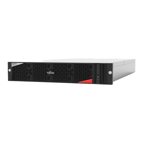
Chapter 1 Product Description 1.1 Overview of the FX700 Main Unit 1.1.1 External Views of the FX700 Main Unit This section shows external views (front, rear, top, right side) of the FX700 main unit. Figure 1.1 Main Unit, Front Figure 1.2 Main Unit, Rear Figure 1.3 Main Unit, Top Figure 1.4 Main Unit, Right Side C120-0089-03EN... -
Page 21: Front Configuration Of The Fx700 Main Unit
Chapter 1 Product Description 1.1 Overview of the FX700 Main Unit 1.1.2 Front Configuration of the FX700 Main Unit This section shows the front of the FX700 main unit. Figure 1.5 Front Configuration of the FX700 Main Unit (With Bezel) Figure 1.6 Front Configuration of the FX700 Main Unit (Without Bezel) Location Component Front panel... -
Page 22: Rear Configuration Of The Fx700 Main Unit
Chapter 1 Product Description 1.1 Overview of the FX700 Main Unit 1.1.3 Rear Configuration of the FX700 Main Unit This section shows the rear of the FX700 main unit. Figure 1.7 Rear Configuration of the FX700 Main Unit Location Component CMU#00 CMU#01 CMU#02 CMU#03 PSU#00 PSU#01... -
Page 23: Lans Of The Fx700 Main Unit
Chapter 1 Product Description 1.1 Overview of the FX700 Main Unit 1.1.4 LANs of the FX700 Main Unit This section shows the locations for the BMC service LAN, BMC management LAN, and node management LAN. Figure 1.8 Rear Locations for the LANs of the FX700 Main Unit Bottom Location Display... -
Page 24: Buttons And Leds On The Fx700 Main Unit
Chapter 1 Product Description 1.2 Buttons and LEDs on the FX700 Main Unit Buttons and LEDs on the FX700 Main Unit The buttons, when operated, power on/off the FX700 main unit. The LEDs indicate various conditions, such as which parts need to be replaced and when they can be replaced. - Page 25 Chapter 1 Product Description 1.2 Buttons and LEDs on the FX700 Main Unit 1.2.1.1 Front Panel Buttons Resetting the BMC during operation may result in abnormal system operation. Figure 1.10 Front Panel Buttons Location Display Button Description Power on/off button Press the button to power on or off the system. - Short press the button to power on all nodes (only if all the nodes in the device are off).
- Page 26 Chapter 1 Product Description 1.2 Buttons and LEDs on the FX700 Main Unit 1.2.1.2 Front Panel LEDs Figure 1.11 Front Panel LEDs Location Display State Description System This device not selected as maintenance identification target LED (front) On, blue This device selected as maintenance target Blinking, blue Maintenance in progress on this device System alarm...
- Page 27 Chapter 1 Product Description 1.2 Buttons and LEDs on the FX700 Main Unit 1.2.1.3 FANU LED Figure 1.12 FANU LED Location State Description FANU alarm LED No failure On, orange This FANU failed C120-0089-03EN...
-
Page 28: Rear Leds On The Fx700 Main Unit
Chapter 1 Product Description 1.2 Buttons and LEDs on the FX700 Main Unit 1.2.2 Rear LEDs on the FX700 Main Unit "Figure 1.13 Locations of the Rear LEDs on the FX700 Main Unit" shows the locations of the rear LEDs on the FX700 main unit. Figure 1.13 Locations of the Rear LEDs on the FX700 Main Unit BMC service LAN System identification LED (rear) - Page 29 Chapter 1 Product Description 1.2 Buttons and LEDs on the FX700 Main Unit 1.2.2.1 Rear LEDs Except LAN LEDs on the Blade Figure 1.15 Rear LEDs Except LAN LEDs on the Blade (1) (2) (3) Location Display State Description Power LED This blade node powered off On, green This blade node powered on Alarm LED...
- Page 30 Chapter 1 Product Description 1.2 Buttons and LEDs on the FX700 Main Unit 1.2.2.2 Rear LAN LEDs on the Blade Figure 1.16 Rear LAN LEDs on the Blade Location State Description LAN speed LED On, orange Indicates data traffic at a transmission speed of 1 Gbit/s. On, green Indicates data traffic at a transmission speed of 100 Mbit/s.
- Page 31 Chapter 1 Product Description 1.2 Buttons and LEDs on the FX700 Main Unit 1.2.2.3 BMCIFU LEDs Figure 1.17 BMCIFU LED (ID) Location Display State Description System This device not selected as maintenance target identification On, blue This device selected as maintenance target LED (rear) Blinking, blue Maintenance in progress on this device C120-0089-03EN...
- Page 32 Chapter 1 Product Description 1.2 Buttons and LEDs on the FX700 Main Unit Figure 1.18 BMCIFU LAN LEDs Location State Description LAN speed LED On, orange Indicates data traffic at a transmission speed of 1 Gbit/s. On, green Indicates data traffic at a transmission speed of 100 Mbit/s. Indicates data traffic at a transmission speed of 10 Mbit/s.
- Page 33 Chapter 1 Product Description 1.2 Buttons and LEDs on the FX700 Main Unit 1.2.2.4 PSU LED Figure 1.19 PSU LED Location State Description Green LED Orange LED PSU status LED No AC output from any PSU connected to device One of following states: - Output stopped due to PSU failure - No AC connection to other PSUs mounted in device, or no AC input to this PSU...
-
Page 34: Chapter 2 Important Information
Chapter 2 Important Information 2.1 Installation Precautions Chapter 2 Important Information This chapter contains important information for using this product correctly and safely. Installation Precautions - Do not install this product in a place where the floor is unstable. Doing so may cause the floor to collapse. -
Page 35: Power, Voltage, And Connection Precautions
Contact your facilities manager or a qualified electrician if you are not sure what type of power is supplied to your building. - Do not use household extension cords with your Fujitsu product. Household extension cords do not have overload protection and are not meant for use with computer systems. Using household extension cords may lead to fire or electric shock. -
Page 36: Environmental Protection
Environmental Protection Environmentally-Friendly Product Design and Development This product has been designed in accordance with the Fujitsu standard for "environmentally friendly product design and development." This means that key factors such as durability, selection and labeling of materials, emissions, packaging, and ease of dismantling and recycling have been taken into account. -
Page 37: Environment Information
Details regarding the return and recycling of devices and consumables within Europe can also be found in the Returning used devices manual. This manual is available at your local Fujitsu branch. Environment Information The following shows the main environment information. - Page 38 Chapter 2 Important Information 2.5 Environment Information Table 2.2 Environment Information PSU Type Multi-Output PSU efficiency at 20% / 50% / 100% of PSU rated output 95.2 / 95.5 / 93.1 power Power factor at 50% of PSU rated output power PSU rated power output (Watts) 1,800 Operating condition class A2 with humidity range from 20% RH to 80% RH...
-
Page 39: Chapter 3 Starting Up
Chapter 3 Starting Up 3.1 Installation Procedure Chapter 3 Starting Up This chapter describes the steps from installation to startup of the FX700 main unit. Installation Procedure This section describes the installation procedure. See and read "Chapter 2 Important Information" thoroughly before performing the work. Decide on the installation site of the FX700 main unit. -
Page 40: Installation Specifications
Chapter 3 Starting Up 3.2 Installation Specifications Installation Specifications The following table shows the installation specifications of the FX700 main unit. Table 3.1 Installation Specifications Item Description External dimensions Width(*1) 482.6 [mm] Depth(*2) Height 86.9 (2U) Weight [kg](*3) 41.8 Air-conditioning Maximum calorific value [kJ/h] 9,803 conditions Exhaust volume [m... - Page 41 Chapter 3 Starting Up 3.2 Installation Specifications Value for an installation with all optional devices mounted. However, it does not include rack mounting rails and cables. (For reference, a rack mounting rail weighs 2.7 kg.) You can calculate the weight according to the device configuration by using the following equation: Weight = 17.7+(4.8 x A)+(1.6 x B)+(1.0 x C)+(0.03 x D) [kg] A = Number of blades mounted (up to 4) B = Number of PSUs mounted (up to 3)
-
Page 42: Installation Environment
Chapter 3 Starting Up 3.3 Installation Environment Installation Environment This section describes the installation environment of the FX700 main unit. 3.3.1 Dust ■ Airborne Particles Ensure that airborne particles in the computer room do not exceed 0.15 mg/m . Most computers are designed to withstand this level of airborne particles. -
Page 43: Seawater (Salt Spray Damage)
Chapter 3 Starting Up 3.4 Distribution Panel Cut-Off Characteristics 3.3.3 Seawater (Salt Spray Damage) Due to the salty air, a large volume of sea salt particles are suspended in the air near coastal areas. If these sea salt particles enter computers, they may cause insulation to fail and parts to corrode or degrade due to moisture and chemical condensation. - Page 44 Chapter 3 Starting Up 3.4 Distribution Panel Cut-Off Characteristics Figure 3.1 Distribution Panel Breaker Characteristics C120-0089-03EN...
-
Page 45: Installation Area And Service Areas
This section describes the installation area and service areas when the FX700 main unit is mounted in a Fujitsu 19-inch rack. The installation area and service areas vary depending on the 19-inch rack used. Figure 3.2 Installation Area and Service Areas... -
Page 46: Rack System Requirements
Basically, this product has been developed for a Fujitsu 19-inch rack. Operation of the FX700 main unit mounted in this rack is guaranteed. To safely use the product mounted in a Fujitsu 19-inch rack, see the related documentation at the following URL: ... - Page 47 Chapter 3 Starting Up 3.6 Rack System Requirements Table 3.4 Mounting Conditions for Third-Party Racks (continued) Check Item Condition Referenced Diagram Check 6 Bracket mounting space There is no interference (by a support upright Figure 3.4 Rack Width for reinforcement or optional mounting) in the shaded area in the diagram.
- Page 48 Chapter 3 Starting Up 3.6 Rack System Requirements Rack Depth Conditions Figure 3.3 Rack Depth Description Front door Front support upright of rack Rear support upright of rack Rear door C120-0089-03EN...
- Page 49 Chapter 3 Starting Up 3.6 Rack System Requirements Rack Width Figure 3.4 Rack Width Description Front door Front support upright of rack Rear support upright of rack Rear door Bracket mounting area Width for mounting brackets Server width Whole server C120-0089-03EN...
- Page 50 Securing work areas for use during maintenance (service areas) Secure service areas for maintenance work by Fujitsu technicians. Determine the service areas by referring to the service areas shown for Fujitsu racks in "3.5 Installation Area and Service Areas"...
-
Page 51: Unpacking The Fx700 Main Unit
The product name and serial number are printed on the nameplate (plate at the top of the FX700 main unit). Figure 3.6 Checking the Product Name and Serial Number Model name (Product name) Serial number Protective film may be affixed to the logos (Fujitsu and FX700). If so, remove all of the film. C120-0089-03EN... -
Page 52: Mounting The Chassis In The Rack
Chapter 3 Starting Up 3.8 Mounting the Chassis in the Rack Mounting the Chassis in the Rack The following is the procedure for mounting the chassis in the rack. 3.8.1 Installing the Rack Rails on the Rack The following is the procedure for installing the rack rails on the rack. Prepare the necessary parts. - Page 53 Figure 3.8 Screw Positions on a Rail When mounting the FX700 main unit in an EIA standard-compliant 19-inch rack not manufactured by Fujitsu, replace the pins on both the left and right rails according to the shape of the rack mounting hole.
- Page 54 Chapter 3 Starting Up 3.8 Mounting the Chassis in the Rack Figure 3.10 After Pin Replacement (Pin Diameter: Φ6.7) Insert the pin at the rear of the right rail into a rack hole. Figure 3.11 Rear of the Rail Pin insertion position Equipment mounting position (2U) View from rear Install the flat plate at the front of the right rail.
- Page 55 Chapter 3 Starting Up 3.8 Mounting the Chassis in the Rack Figure 3.12 Front of the Rail Countersunk head screw x 2 Flat plate x 1 Fix the rear of the right rail in place. When using Φ6.5 pins, fix it in place with countersunk head screws directly without washers, depending on the size of the rack mounting hole.
-
Page 56: Mounting The Chassis In The Rack
Chapter 3 Starting Up 3.8 Mounting the Chassis in the Rack Figure 3.14 Screw Positions on the Rail Repeat steps 3 to 6 to install the left rail too in the same way. Figure 3.15 After the Rails are Installed 3.8.2 Mounting the Chassis in the Rack The following is the procedure for mounting the chassis in the rack. - Page 57 Chapter 3 Starting Up 3.8 Mounting the Chassis in the Rack "3.10.2 Removing the PSU From the Chassis," "3.13.2 Removing the FANU From the Chassis," "3.11.2 Removing the Dummy Blade From the Chassis." - At least two people are required to perform the work of mounting the chassis in the rack. Insert the chassis along the rails into the rack.
-
Page 58: Installing/Removing The Blade
Chapter 3 Starting Up 3.9 Installing/Removing the Blade Install the left and right back plates onto the rack. Figure 3.18 Installing the Back Plates M5 screw x 2 Support bracket After mounting the chassis, install all the units. For details on how to install each unit, see "3.9.1 Installing the Blade in the Chassis,"... -
Page 59: Removing The Blade From The Chassis
Chapter 3 Starting Up 3.9 Installing/Removing the Blade Figure 3.19 Installing the Blade Lock Remarks Push the device until it is locked. Note - At any location where no blade will be mounted, a dummy blade must be installed. For details on how to install a dummy blade, see "3.11.1 Installing the Dummy Blade in the Chassis."... -
Page 60: Installing/Removing The Psu
Chapter 3 Starting Up 3.10 Installing/Removing the PSU Figure 3.20 Removing the Blade 3.10 Installing/Removing the PSU 3.10.1 Installing the PSU in the Chassis The following is the procedure for installing the PSU in the chassis. Install the PSU in the chassis. Figure 3.21 Installing the PSU Lock C120-0089-03EN... -
Page 61: Removing The Psu From The Chassis
Chapter 3 Starting Up 3.11 Installing/Removing the Dummy Blade Remarks - The PSU must be installed with the lock facing right when viewed from the back. - Push the device until it is locked. At any location where no PSU will be mounted, a dummy PSU must be installed. For details on how to install a dummy PSU, see "3.12.1 Installing the Dummy PSU in the Chassis."... -
Page 62: Removing The Dummy Blade From The Chassis
Chapter 3 Starting Up 3.11 Installing/Removing the Dummy Blade Figure 3.23 Installing the Dummy Blade Lock Knob Note - When inserting the dummy blade, be careful not to allow foreign objects, such as cables, to enter the chassis. 3.11.2 Removing the Dummy Blade From the Chassis This section describes how to remove the dummy blade from the chassis. -
Page 63: Installing/Removing The Dummy Psu
Chapter 3 Starting Up 3.12 Installing/Removing the Dummy PSU 3.12 Installing/Removing the Dummy PSU 3.12.1 Installing the Dummy PSU in the Chassis This section describes how to install the dummy PSU in the chassis. While pushing the lock (1), install the dummy PSU in the direction of the arrow (2). Figure 3.25 Installing the Dummy PSU Push in the dummy PSU until it is locked. -
Page 64: Installing/Removing The Fanu
Chapter 3 Starting Up 3.13 Installing/Removing the FANU Figure 3.26 Removing the Dummy PSU 3.13 Installing/Removing the FANU 3.13.1 Installing the FANU in the Chassis The following is the procedure for installing the FANU in the chassis. Install the FANU in the chassis. Figure 3.27 Installing the FANU Lock Front panel... -
Page 65: Removing The Fanu From The Chassis
Chapter 3 Starting Up 3.13 Installing/Removing the FANU - Push the device until it is locked. Repeat step 1 to install a FANU in every other mounting location. Figure 3.28 FANU Installation Completed Install the bezel. Figure 3.29 Installing the Bezel Guide pin Screw Guide pin Screw Insert the left and right guide pins into the chassis, and fix the front panel in place with two... - Page 66 Chapter 3 Starting Up 3.13 Installing/Removing the FANU Figure 3.30 Unlocking the FANU Remarks The following shows the places to hold a FANU when removing it. Figure 3.31 Places to Hold a FANU When Removing It Example Thumb Index Finger Operation with right hand Operation with left hand While pushing the second lock (3), pull out the FANU from the chassis.
-
Page 67: Input Power Connection Specifications
Chapter 3 Starting Up 3.14 Input Power Connection Specifications Figure 3.32 Removing the FANU 3.14 Input Power Connection Specifications This section describes the input power connection specifications of the FX700 main unit. 3.14.1 Input Power Connection Specifications (FX700 Main Unit) The following table shows the input power connection specifications of the FX700 main unit. Table 3.5 Power Cord Specifications Destination Connector... -
Page 68: Connecting Cables
Chapter 3 Starting Up 3.16 Powering On for the First Time 3.15 Connecting Cables This section contains precautions and information on connecting cables. 3.15.1 Precautions on Connecting/Disconnecting Cables - Always read the documentation supplied with the device you want to connect. Never connect or disconnect cables during a thunderstorm. -
Page 69: Ac Power On
FUJITSU Supercomputer PRIMEHPC FX700 BMC User's Guide (C120-0091EN). Logging in to the BMC For details on how to log in to the BMC, see "2.1.1 Login" in the FUJITSU Supercomputer PRIMEHPC FX700 BMC User's Guide (C120-0091EN). Setting the Time To set the BMC time, select [Time Settings] from the [Configuration] menu. -
Page 70: Installing The Os
Checking the Configuration To check the configuration, select [FRU Information] from the [Server Status] menu. For details, see "3.1 Server Status" in the FUJITSU Supercomputer PRIMEHPC FX700 BMC User's Guide (C120-0091EN). Powering Off To power off, control the power from [Power Control] in the [Power Control] menu. For details, see "3.3 Power Control"... - Page 71 Chapter 3 Starting Up 3.17 Installing the OS After creating the installation DVD, install the OS from the network using the PXE server. Install it according to "Installing the OS From the Network." Installing the OS From the Network The following is the procedure for installing the OS from the network. Remarks The MAC address information for each node is required for OS installation.
-
Page 72: Os Driver Installation Procedure
Specify "Power on" in [Power Control] on the [Power Control] screen of the Web GUI. Specify "02h" in [Boot Script Number]. For details, see "3.3 Power Control" in the FUJITSU Supercomputer PRIMEHPC FX700 BMC User's Guide (C120-0091EN). Install the OS. -
Page 73: Installing The Infiniband Driver
3.18 Installing the InfiniBand Driver The InfiniBand driver (Mellanox OFED) and installation procedure can be found online. For the Japanese market https://www.fujitsu.com/jp/products/computing/servers/supercomputer/downloads/ For the global market https://www.fujitsu.com/global/products/computing/servers/supercomputer/documents/ Only the specified driver versions described on the above sites are supported. C120-0089-03EN... -
Page 74: Chapter 4 Operation
"3.2 Installation Specifications." Failure to operate the equipment within the prescribed temperature range may lead to malfunctions or loss of data. Fujitsu is not responsible for any damage or failure caused by use of the equipment outside the temperature range for guaranteed operation. -
Page 75: Removing The Chassis
Chapter 4 Operation 4.2 Removing the Chassis the procedure in "3.3 Power Control" in the FUJITSU Supercomputer PRIMEHPC FX700 BMC User's Guide (C120-0091EN). Removing the Chassis 4.2.1 Removing the Chassis From the Rack The following is the procedure for removing the chassis from the rack. - Page 76 Chapter 4 Operation 4.2 Removing the Chassis Figure 4.2 Removing the Thumb Screws Thumb screws at 2 places Remove the chassis from the rack. Figure 4.3 Removing the Chassis C120-0089-03EN...
-
Page 77: Cleaning The Fx700 Main Unit
Chapter 4 Operation 4.3 Cleaning the FX700 Main Unit Cleaning the FX700 Main Unit - Power off the FX700 main unit. Then, disconnect the power plugs from their properly grounded outlets. - Do not clean the internal components yourself. Instead, ask a service technician. - Do not use cleaning agents that contain abrasive materials or that can cause plastics to corrode. -
Page 78: Chapter 5 Collecting Information When Troubleshooting
- The file No. corresponds to [No.] in [Snapshot Files]. Click the name of the collected file to save it in the folder of your choice. Hardware Trouble If an alarm LED lights up or is blinking, plan maintenance according to the FUJITSU Supercomputer C120-0089-03EN... -
Page 79: Os Driver-Related Problems
When not using operations management software, collect the dump by issuing a OS dump collection instruction from "Power Control" on the BMC Web GUI. For details, see "3.3 Power Control" in the FUJITSU Supercomputer PRIMEHPC FX700 BMC User's Guide (C120-0091EN). -
Page 80: Node Console Hangs
Chapter 5 Collecting Information When Troubleshooting 5.4 Other Problems - While both the BMC management LAN port and BMC service LAN port are disabled, powering on the BMC enables the LAN ports. Set the IP addresses for both the BMC management LAN and BMC service LAN. 5.4.2 Node Console Hangs If the console cannot be end normally, it may hang. -
Page 81: Precaution On Using The Web Gui
Chapter 5 Collecting Information When Troubleshooting 5.4 Other Problems 5.4.5 Precaution on Using the Web GUI Multiple accesses from the same PC are not supported. The following message appears when multiple accesses are attempted. If the message appears, close the session. Figure 5-2 Message From the Webpage C120-0089-03EN... -
Page 82: Chapter 6 Technical Specifications
FX700 Main Unit Specifications Detailed technical specifications are printed on the data sheet of the FX700 main unit. The data sheet is provided online. - For the Japanese market: https://www.fujitsu.com/jp/products/computing/servers/supercomputer/downloads/ - For the global market: https://www.fujitsu.com/global/products/computing/servers/supercomputer/documents/ Table 6.1 FX700 Main Unit Specifications Name A64FX™... -
Page 83: Appendix A Bmc Driver Messages
Collect investigation data according to "5.3.1 Collecting Information for Maintenance Purposes," and then contact Fujitsu Support with the collected data together with the output message. [ERR.] xos BMC 0002 - internal information Invalid parameter. File Name Size:[NAME] Data Size:[DATA] Name:[PTR1] Data:[PTR2] Meaning A specified value is invalid as an emergency dump request parameter. - Page 84 Collect investigation data according to "5.3.1 Collecting Information for Maintenance Purposes," and then contact Fujitsu Support with the collected data together with the output message. [ERR.] xos BMC 0006 - internal information Detected hard error. [CODE] Meaning A hardware error response was received from the BMC.
- Page 85 Collect investigation data according to "5.3.1 Collecting Information for Maintenance Purposes," and then contact Fujitsu Support with the collected data together with the output message. [ERR.] xos BMC 0012 - internal information Unable to allocate device file. Meaning Securing a char-type device failed.
- Page 86 Collect investigation data according to "5.3.1 Collecting Information for Maintenance Purposes," and then contact Fujitsu Support with the collected data together with the output message. [ERR.] xos BMC 0018 - internal information Could not Create procfs entry. Meaning A proc file entry could not be created.
- Page 87 Collect investigation data according to "5.3.1 Collecting Information for Maintenance Purposes," and then contact Fujitsu Support with the collected data together with the output message. [ERR.] xos BMC 0024 - internal information BMC is not ready to accept the command. [CODE] Meaning The BMC is not ready to accept the command.
- Page 88 Meaning The system received a Shutdown notification and is powering off. Action No action is necessary. [INFO] xos BMC 1005 - internal information Copyright(c) 2018 FUJITSU LIMITED All rights reserved. Meaning The message displays the copyright to the BMC driver.
- Page 89 Appendix A BMC Driver Messages [INFO] xos BMC 1008 - internal information Started the Emergency dump. Meaning An emergency dump request has begun. Action No action is necessary. [INFO] xos BMC 1009 - internal information Started loading BMC driver. Meaning The BMC driver is being loaded. Action No action is necessary.
-
Page 90: Appendix B Cpu-Mem-Ras Driver Messages
Collect investigation data according to "5.3.1 Collecting Information for Maintenance Purposes," and then contact Fujitsu Support with the collected data together with the output message. [ERR.] xos RAS 0001 - internal information HOST SOFTWARE ERROR request_irq failed. (ERR1) Meaning Registration of the interrupt handler for HOST SOFTWARE ERROR failed. - Page 91 Collect investigation data according to "5.3.1 Collecting Information for Maintenance Purposes," and then contact Fujitsu Support with the collected data together with the output message. [ERR.] xos RAS 0006 - internal information ioremap failed for GICv3_ITS_CNTL_REG. Meaning Memory mapping to the GICv3 Distributor (ITS) area failed.
- Page 92 Collect investigation data according to "5.3.1 Collecting Information for Maintenance Purposes," and then contact Fujitsu Support with the collected data together with the output message. [ERR.] xos RAS 0012 - internal information Uncorrectable Error RAW L2 detected. Meaning A raw UE detected on the L2 cache was not error-marked.
- Page 93 Action Collect investigation data according to "5.3.1 Collecting Information for Maintenance Purposes," and then contact Fujitsu Support with the collected data together with the output message. [ERR.] xos RAS 0017 - internal information Internal control register detected. esr=DATA1 ERR0STATUS=DATA2 Meaning An undefined error was detected.
- Page 94 Collect investigation data according to "5.3.1 Collecting Information for Maintenance Purposes," and then contact Fujitsu Support with the collected data together with the output message. [ERR.] xos RAS 0022 - internal information FP&SIMD, vector, predicate register error detected. esr=DATA1 ERR0STATUS=DATA2 Meaning A parity error was detected in the FP&SIMD register.
- Page 95 "5.3.1 Collecting Information for Maintenance Purposes," and then contact Fujitsu Support with the collected data together with the output message. [ERR.] xos RAS 0026 - internal information A pending error was not detected even though an interrupt was received. GICD_FJ_GIC_HOST_SOFTWARE_ERROR_PENDING=DATA1 Meaning No pending error was detected even though an interrupt was received.
- Page 96 Collect investigation data according to "5.3.1 Collecting Information for Maintenance Purposes," and then contact Fujitsu Support with the collected data together with the output message. Information Message [INFO] xos RAS 0000 - internal information No need to clear ERR0STATUS register.