
Related Manuals for Moffat Waldorf RN8110GC


Summary of Contents for Moffat Waldorf RN8110GC
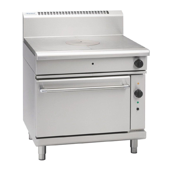
- Page 1 I n s t a l l a t i o n a n d O p e r a t i o n M a n u a l Target Top Convection Oven Range RN8110GC Date Purchased Serial Number Dealer Service Provider For use in GB &...
- Page 2 The reproduction or copying of any part of this manual by any means whatsoever is strictly forbidden unless authorized previously in writing by the manufacturer. In line with policy to continually develop and improve its products, Moffat Ltd. reserves the right to change the specifications and design without prior notice.
-
Page 3: Table Of Contents
Contents Waldorf Gas Target Top Convection Oven Range RN8110GC Gas Target Top Convection Oven Range. Introduction ....................2 Specification ....................3 Model Numbers Covered in this Specification General Gas Supply Requirements Gas Connection Electrical Supply Requirements Dimensions ....................5 Installation ....................6 Installation Requirements Unpacking Location... -
Page 4: Introduction
Introduction We are confident that you will be delighted with your WALDORF Target Top Convection Oven Range and it will become a most valued appliance in your commercial kitchen. To ensure you receive the utmost benefit from your new Waldorf appliance, there are two important things you can do. -
Page 5: Specification
Specifications Model Numbers Covered in this Specification RN8110GC Gas Target Top Convection Oven Range. General A commercial heavy duty, general purpose fully modular, gas fired Target Top Convection Oven Range, having a high output, two stage double-ring iron cast burner offering accurate temperature control and infinitely variable heat with the heat radiating out from the centre of the Target Top. -
Page 6: Electrical Supply Requirements
Specifications Gas Connection Gas supply connection point is located at the rear of the appliance, approximately 130mm from the right hand side, 35mm from the rear and 655mm from the floor and is reached from beneath the appliance. (Refer to the ‘Dimensions’ section). Connection is ¾"... -
Page 7: Dimensions
Dimensions RN8110GC... -
Page 8: Installation
Installation Installation Requirements NOTE: • It is most important that this appliance is installed correctly and that operation is correct before use. Installation shall comply with local gas, electrical and health and safety requirements. • This appliance shall be installed with sufficient ventilation to prevent the occurrence of unacceptable concentrations of health harmful substances in the room, the appliance is installed in. -
Page 9: Clearances
Installation Clearances Combustible Surface Non Combustible Surface Left/Right hand side 50 mm 0 mm Rear 50 mm 0 mm NOTE: Only non-combustible materials can be used in close proximity to this appliance. Assembly NOTE: • All Models are delivered completely assembled. No further assembly is required. Refer to the information below for assembly instructions. -
Page 10: Electrical Connection
Installation Correctly locate the appliance into its final operating position and using a spirit level, adjust the legs so that the appliance is level and at the correct height. Connect the gas supply to the appliance. A suitable joining compound which resists the breakdown action of LPG must be used on every gas line connection, unless compression fittings are used. -
Page 11: Operation
Operation Operation Guide AUTIO N • This appliance is for professional use and is only to be used by qualified people. • Only authorised service persons should be used to carry out installation, servicing or gas conversion operations. • Components having adjustments protected... -
Page 12: Lighting The Pilot Burner (Target Top)
Operation Lighting the Pilot Burner (Target Top) Remove centre casting with the casting removal tool. Depress the control knob and rotate anti-clockwise to the ‘PILOT’ position. With the control knob depressed, manually light the pilot burner located in front of the main burner. Hold in the control knob for approximately 10 to 15 seconds, then release. -
Page 13: Oven - Main Burner / Thermostat
Operation Oven Pilot Ignition This oven is fitted with a pilot as a standard option and flame failure protection, which is incorporated by way of a thermo-electric system for the main burner. Flame failure protection will shut off the gas supply This is an to the burner in the event that the pilot burner goes out, so that un-burnt gas is not expelled. -
Page 14: Oven 'Shut Down
Operation Oven ‘Shut-Down’ To ‘Shut Down’ the oven, turn the oven thermostat to the ‘0’ position, the oven main burners will go out. Turn the gas control valve to the 'OFF' position and this will extinguish the pilot burner. (To relight the pilot burner, refer to ‘Oven Pilot Ignition’... -
Page 15: Cleaning And Maintenance
Cleaning and Maintenance AUTIO N Always turn 'Off' the gas and electrical supply at the mains supply before cleaning. This appliance is not water proof. Do not use water jet spray to clean interior or exterior of this appliance. General Clean the Target Top / Range regularly. - Page 16 Cleaning and Maintenance b. Clean any food residue and spillage from the channels around the centre casting and main plates before use. c. DO NOT use water on the castings while they are still hot as cracking may occur. Should it be necessary to clean the castings, allow the castings to cool and then remove for cleaning.
-
Page 17: Fault Finding
Fault Finding This section provides an easy reference guide to the more common problems that may occur during the operation of your appliance. The fault finding guide in this section is intended to help you correct, or at least accurately diagnose problems with your appliance. Although this section covers the most common problems reported, you may encounter a problem not covered in this section. -
Page 18: Wiring Schematic
Wiring Schematic Wiring Schematic RN8110GC... -
Page 19: Gas Conversion And Specifications
Gas Conversion and Specifications Conversion Procedure AUTIO N Ensure that the Unit is isolated from the gas supply before commencing servicing. NOTE: • These conversions should only be carried out by qualified persons. All connections must be checked for leaks before re-commissioning the appliance. •... - Page 20 Gas Conversion and Specifications Target Top - Pilot Burner Main Burner Pilot Burner To remove the pilot burner, disconnect the gas Injectors supply tube from the base of the pilot burner. Remove the bolt securing the retaining plate holding the pilot burner and thermo couple to the mounting bracket.
- Page 21 Gas Conversion and Specifications Oven Pilot Burner Sole Plate Inspection Covers Main Injector With the gas supply turned off at the main supply, unscrew and remove the 6 screws securing the lower lintel to the front of the oven. Remove the lintel from the oven. Open the oven door and remove the cast sole plate from inside the oven.
- Page 22 Gas Conversion and Specifications Gas Regulator NOTE: The regulator supplied is convertible between Natural Gas and LPG, but it’s outlet pressure is fixed ex-factory and is NOT to be adjusted. NOTE, Pin rotated for Natural Gas NOTE, Pin rotated for LPG Fig 21 Ensure that the gas supply is turned ‘OFF’...
-
Page 23: Gas Specifications
Gas Conversion and Specifications Gas Specifications - Australia / New Zealand Only Nat. Gas LP Gas (Propane) Main Burner Injector (Inner Ring) Ø 1.70 mm Ø 1.10 mm Main Burner Injector (Outer Ring) Ø 2.60 mm Ø 1.55 mm Pilot Burner Injector 0.35 0.25 Target Top... -
Page 24: Replacement Parts List
Replacement Parts List Replacement Parts List IMPORTANT: Only genuine authorized replacement parts should be used for the servicing and repair of this appliance. The instructions supplied with the parts should be followed when replacing components. For further information and servicing instructions, contact your nearest authorized service branch (contact details are as shown on the reverse of the front cover of this manual). - Page 25 Replacement Parts List General 227012 Centre Casting. 227013 Half Plate Casting. 014997 Casting Removal Tool. 227892 Oven Side Rack LH. 227893 Oven Side Rack RH. 023068 Side Rack Screw. 232350 Baffle. 227896 Oven Rack. 228883 Spill Tray 450mm. 227850 Adjustable leg - 150 mm. Regulator 228531 Regulator (Natural Gas / LP Gas [Propane] - convertible) - ¾”...