Table of Contents
Advertisement
Quick Links
I n s t a l l a t i o n a n d O p e r a t i o n M a n u a l
Gas Cooktops
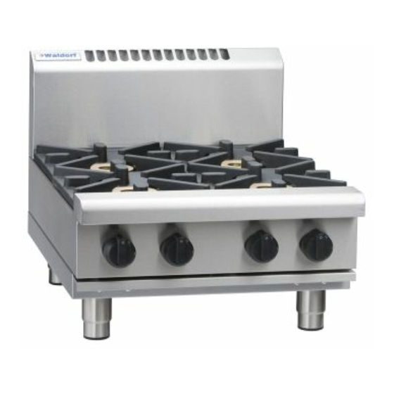
RN8200G
RNL8200G
RN8400G
RNL8400G
RN8600G
RNL8600G
RN8800G
RNL8800G
Date Purchased
Serial Number
Dealer
Service Provider
Series
RNB8200G
RNB8400G
RNB8600G
RNB8800G
RNLB8200G
RNLB8400G
RNLB8600G
RNLB8800G
For use in GB, IE & DK
228605-26
Advertisement
Table of Contents

Related Manuals for Moffat Waldorf RN8200G


Summary of Contents for Moffat Waldorf RN8200G
- Page 1 I n s t a l l a t i o n a n d O p e r a t i o n M a n u a l Gas Cooktops Series RN8200G RNL8200G RNB8200G RNLB8200G RN8400G RNL8400G RNB8400G RNLB8400G RN8600G RNL8600G...
- Page 2 The reproduction or copying of any part of this manual by any means whatsoever is strictly forbidden unless authorized previously in writing by the manufacturer. In line with policy to continually develop and improve its products, Moffat Ltd. reserves the right to change the specifications and design without prior notice.
-
Page 3: Table Of Contents
Contents Waldorf Gas Cooktops RN(L)(B)8200G Gas Cooktop 300mm wide. RN(L)(B)8400G Gas Cooktop 600mm wide. RN(L)(B)8600G Gas Cooktop 900mm wide. RN(L)(B)8800G Gas Cooktop 1200mm wide. Introduction ....................2 Specification ....................3 Model Numbers Covered in this Specification General Gas Supply Requirements Gas Connection Dimensions .................... -
Page 4: Introduction
Introduction We are confident that you will be delighted with your WALDORF GAS COOKTOP, and it will become a most valued appliance in your commercial kitchen. To ensure you receive the utmost benefit from your new Waldorf Gas Cooktops, there are two important things you can do. -
Page 5: Specification
Specifications Model Numbers Covered in this Specification RN[1]8200G-[2]-[3] 2 Open Burners. RN[1]8203G -[3] 300mm Griddle. RN[1]8400G-[2]-[3] 4 Open Burners. RN[1]8403G-[2]-[3] 2 Open Burners + 300mm Griddle. RN[1]8406G -[3] 600mm Griddle. RN[1]8600G-[2]-[3] 6 Open Burners. RN[1]8603G-[2]-[3] 4 Open Burners + 300mm Griddle. RN[1]8606G-[2]-[3] 2 Open Burners + 600mm Griddle. -
Page 6: Gas Supply Requirements
Specifications Gas Supply Requirements - Australia Natural Gas LP Gas (Propane) Input Rate (N.H.G.C.) 28 MJ/hr 28 MJ/hr - each Open Burner - each 300mm Griddle Section 21 MJ/hr 21 MJ/hr 1.13 - 3.40 kPa 2.75 - 4.50 kPa Supply Pressure Burner Operating Pressure (*) 0.95 kPa 2.6 kPa... -
Page 7: Gas Connection
Specifications - All Other Markets Natural Gas Town Gas (**) Input Rate (N.H.G.C.) - each Open Burner 28 MJ/hr 28 MJ/hr - each 300mm Griddle Section 21 MJ/hr 21 MJ/hr Supply Pressure 1.13 - 3.40 kPa 0.75 - 1.50 kPa Burner Operating Pressure (*) 0.95 kPa 0.63 kPa... -
Page 8: Dimensions
Dimensions Bench Models RN(L)8200G-B = Rating Plate Location for this option. RN(L)8400G-B RN(L)8600G-B RN(L)8800G-B Refer to Page 9 for Cooktop options... - Page 9 Dimensions Cabinet Base Models RN8200G Models - not available in Cabinet Base option. = Rating Plate Location for RN(L)8400G-CB this option. RN(L)8600G-CB RN(L)8800G-CB Refer to Page 9 for Cooktop options...
- Page 10 Dimensions Leg Stand Models RN8200G Models - not available in Leg Stand Base option. = Rating Plate Location for RN(L)8400G-LS this option. RN(L)8600G-LS RN(L)8800G-LS Refer to Page 9 for Cooktop options...
- Page 11 Dimensions Refrigerated Base Models RN8200G and RN8400G Models - not available in Refrigerated Base option. = Rating Plate Location for this option. RN(L)8600G-RB RN(L)8800G-RB Refer to Page 9 for Cooktop options...
- Page 12 Dimensions Cooktop Options RN(L)8800G RN(L)8600G RN(L)8400G RN(L)8200G RN(L)8803G RN(L)8203G RN(L)8603G RN(L)8403G RN(L)8806G RN(L)8606G RN(L)8406G RN(L)8809G RN(L)8609G NOTE: RN8200G models are only available in Bench Model (-B) option. RN8400G models are available in Bench Model (-B), Cabinet Base (-CB), or Leg Stand (-LS) model options.
-
Page 13: Installation
Installation Installation Requirements NOTE: It is most important that this Cooktop is installed correctly and that operation is correct before use. Installation shall comply with local gas, health and safety requirements. This appliance shall be installed with sufficient ventilation to prevent the occurrence of unacceptable concentrations of health harmful substances in the room, the appliance is installed in. -
Page 14: Clearances
Installation Clearances NOTE: Only non-combustible materials can be used in close proximity to this appliance. Combustible Surface Non Combustible Surface Left / Right Hand Side 250mm (*) Rear; - 50mm Standard Models 100mm Low Back Models Side clearances can be 50mm when adjacent surface is at least 100mm below cooking surface. Assembly NOTE: ... - Page 15 Installation Rear Adjustable Feet, fitting:- Secure rear of base tray to rear cooktop legs by screwing the two adjustable feet supplied, into base of rear cooktop legs. Secure each adjustable foot, hand tight. Cooktop Rear Rollers, fitting:- Fit rear leg securing bolts up through Leg Mount centre of rear leg housings to secure Points...
-
Page 16: Fitting Adjustable Feet / Rear Rollers To Cabinet And Refrigeration Bases
Installation Fitting Adjustable Feet / Rear Rollers to Cabinet and Refrigeration Bases. Rear Adjustable Feet, fitting:- Raise appliance from floor by approximately 75 mm using suitable lifting equipment (i.e. Cabinet / Palletiser / Forklift) to allow rear rollers to be Refrigeration removed. -
Page 17: Gas Connection
Installation Gas Connection NOTE: ALL GAS FITTING MUST ONLY BE CARRIED OUT BY A QUALIFIED PERSON. Waldorf Cooktops do not require electrical connection, as they function totally on the gas supply. It is essential that gas supply is correct for Cooktop being installed and that adequate supply pressure and volume are available. -
Page 18: Commissioning
Installation Commissioning Before leaving the new installation; a. Check the following functions in accordance with operating instructions specified in ‘Operation’ section of this manual. Lighting the Griddle. Light the Open Burners. (F - Flame Failure Option). Light the Open Burners. (PF - Pilot and Flame Failure Option). ... -
Page 19: Operation
Operation Operation Guide Caution This appliance is for professional use and is only to be used by qualified persons. Only authorised service persons are to carry out installation, servicing or gas conversion operations. Components having adjustments protected (e.g. -
Page 20: Open Burners ('F' - Flame Failure Option)
Operation Open Burners ('F' - Flame Failure Option) Lighting the Open Burners Flame Failure Protection is incorporated for each burner by way of a thermo-electric system which will shut off gas supply to that burner in the event that burner goes out, so that un-burnt gas is not expelled. -
Page 21: Griddle
Operation Griddle Lighting the Griddle a. Depress gas control knob and rotate anti-clockwise to ‘PILOT’ position. b. Hold gas control knob depressed, press piezo ignition button to ignite pilot burner. Repeat Items 1 to 2 until pilot is lit. c. Release gas control knob approximately 10-20 seconds after lighting pilot. d. -
Page 22: Cleaning And Maintenance
Cleaning and Maintenance Before Commencing Cleaning Caution Always turn off the gas / electrical supply before cleaning the appliance. This appliance is not water proof. Do not use water jet spray to clean interior or exterior of this appliance. NOTE: ... -
Page 23: Open Burner Cleaning
Cleaning and Maintenance Open Burner Cleaning Griddle Plate Cleaning 1. Remove pot stands, burner caps, burner bowls It is recommended that a flat blade scraper is used to clean the griddle surface, these are not supplied and pot stand supports from top of cooktop. Wash with hot soapy water, using a soft with griddle but may be purchased separately. -
Page 24: Fault Finding
Fault Finding This section provides an easy reference guide to the more common problems that may occur during operation of your equipment. The fault finding guide in this section is intended to help you correct, or at least accurately diagnose problems with your equipment. Although this section covers the most common problems reported, you may encounter a problem not covered in this section. -
Page 25: Gas Conversion And Specifications
Gas Conversion and Specifications Conversion Procedure Caution Ensure that the Appliance is isolated from the gas supply before commencing servicing. NOTE: These conversions should only be carried out by qualified persons. All connections must be checked for leaks before re-commissioning the appliance. ... - Page 26 Gas Conversion and Specifications Griddle Piezo Igniter Pilot Supply Tube Carry out the following:- Remove griddle plate section and heat shield. Remove main burner. Disconnect piezo igniter from mounting Pilot Burner bracket. (For access purposes). Disconnect pilot supply tube from pilot burner to access pilot injector.
- Page 27 Gas Conversion and Specifications Gas Regulator NOTE, Pin rotated - NAT Gas / LPG / Butane Only. for Natural Gas NOTE: The gas regulator supplied is convertible between Natural Gas and LP Gas, but it’s outlet NOTE, Pin rotated for LPG pressure is fixed ex-factory and is NOT to be adjusted.
-
Page 28: Gas Specifications
Gas Conversion and Specifications Gas Specifications - Australia Natural. Gas LP Gas (Propane) Main Burner Ø 2.45mm Ø 1.50mm Open Burner Pilot Burner ('PF' Models Only) 0.30 0.20 Main Burner Ø 2.10mm Ø 1.30mm Pilot Burner 0.35 0.23 Griddle Burner Aeration Setting Fully open Fully open Supply Pressure... - Page 29 Gas Conversion and Specifications - All Other Markets Natural Gas Town Gas (**) Main Burner Ø 2.45mm Ø 4.50mm Open Burner Pilot Burner ('PF' Models only) 0.30 0.60 Main Burner Ø 2.10mm Ø 3.40mm Griddle Pilot Burner 0.35 0.60 Burner Aeration Setting Fully open Fully open Supply Pressure...
-
Page 30: Replacement Parts
Replacement Parts List Replacement Parts List IMPORTANT: Only genuine authorized replacement parts should be used for servicing and repair of this appliance. Instructions supplied with parts should be followed when replacing components. further information servicing instructions, contact your nearest authorized service branch (contact details are as shown on reverse of front cover of this manual). - Page 31 Replacement Parts List General 227015 Pot Stand. 228881 Spill Tray 300mm (RN8200G Series). 228882 Spill Tray 600mm (RN8400G / RN8800G Series). 228883 Spill Tray 450mm (RN8600G Series). 227855 Adjustable Leg (84mm - Bench Models). 227850 Adjustable Leg (Flush Stud) (150mm - CB / RB Models). 227851 Adjustable Leg Extd.