Table of Contents
Advertisement
Advertisement
Chapters
Table of Contents

Related Manuals for Moffat Turbofan E32


Summary of Contents for Moffat Turbofan E32
- Page 1 E32 CONVECTION OVEN SERVICE MANUAL Revision 2/F3509...
-
Page 2: Table Of Contents
CONTENTS This manual is designed to take a more in depth look at the E32 convection oven for the purpose of making the unit more understandable to service people. There are settings explained in this manual that should never require to be adjusted, but for completeness and those special cases where these settings are required to change, this manual gives a full explanation as to how, and what effects will result. -
Page 3: Specifications
1. SPECIFICATIONS MODEL: E32 (28.0) (31.5) (1.95) (2.95) FRONT SIDE PLAN LEGEND - Electrical connection entry point - Water entry - 3/4” BSP hose connection Dimensions shown in millimetres. Dimensions in inches shown in brackets. Revision 2/F3509... - Page 4 LOCATION To ensure correct ventilation for the motor and controls the following minimum installation clearances are to be adhered to: Rear 40mm / 1.5“ Left-hand side 40mm / 1.5” Right-hand side 40mm / 1.5” OVEN INTERNAL DIMENSIONS Width 468 mm / 18.5” Height 533 mm / 21”...
-
Page 5: Installation
2. INSTALLATION WARNING: THIS APPLIANCE MUST BE GROUNDED. WARNING: ALL INSTALLATION AND SERVICE REPAIR WORK MUST BE CARRIED OUT BY QUALIFIED PERSONS ONLY. It is most important that the oven is installed BEFORE USE correctly and that the operation is correct be- Operate the oven for about 1 hour at 200°C fore use. - Page 6 Ensure that they are tight. Figure 2.3 DOUBLE STACKING UNITS When it is desired to mount an E32 Turbofan oven on an E87 prover, a double stacking kit must be used. Available from your dealer or Turbofan distributor. (see Spare Parts).
- Page 7 RATING PLATE LOCATION flush with the sides of the oven base. Be The rating plate for the E32 convection oven sure to have the large flange of the shroud is located at the bottom right corner of the RH back at the rear of the oven.
-
Page 8: Operation
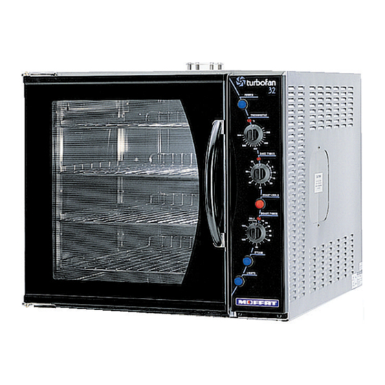
3. OPERATION NOTE: A full user’s operation manual is supplied with the product and can be used for further referencing of installation, operation and service. 3.1 DESCRIPTION OF CONTROLS 1. POWER Depress to switch power on or off (switch illuminates when power is on). 2. -
Page 9: Explanation Of Control System
With the power switch Off all functions of the oven are The E32 Turbofan convection oven has 6.5 inoperable. kW of electric heating elements, comprising of a 3 kW inner coil, and a 3.5 kW outer coil,... - Page 10 position one is used to supply power to its timing motor and the other is used to switch power directly to the main oven thermostat. During the 3 hour timer run-down period the oven temperature will be controlled by the main oven thermostat to the set temperature and operate as previously described.
-
Page 11: Maintenance
4. MAINTENANCE WARNING: ALL INSTALLATION AND SERVICE REPAIR WORK MUST BE CARRIED OUT BY QUALIFIED PERSONS ONLY. 4.1 CLEANING washed in the sink, but take care not to cut or damage them. To replace, ensure that the lip is facing the oven opening. Fit the WARNING: ALWAYS TURN THE top and bottom seals first, then the side POWER SUPPLY OFF BEFORE... -
Page 12: Routine Procedures
4.2 ROUTINE PROCEDURES PROCEDURE INTERVAL DOOR SEALS Check for deterioration. 12 months DOOR PIVOT BUSHES Check for wear. 12 months DOOR CATCH Ensure that catch is adjusted such that the door closes 12 months properly. ELEMENT Check that element resistance is correct to it’s rating 12 months (refer 6.3.15). -
Page 13: Trouble Shooting Guide
5. TROUBLE SHOOTING WARNING: ALL INSTALLATION AND SERVICE REPAIR WORK MUST BE CARRIED OUT BY QUALIFIED PERSONS ONLY. FAULT POSSIBLE CAUSE REMEDY THE OVEN DOES NOT The mains isolating switch on Turn on. OPERATE / START the wall, circuit breaker or fuses are “off”... - Page 14 FAULT POSSIBLE CAUSE REMEDY CONTINUOUS WATER OUT With oven on only—Electrical Correct electrical fault. OF OVEN WATER NOZZLE fault. (Refer fault diagnosis 6.1.6) With oven on or off—Fault with Service or replace as required. water valve. (Refer service section 6.3.12, (Refer fault diagnosis 6.1.5) 6.3.13) 60 MINUTE TIMER WILL NOT...
- Page 15 FAULT POSSIBLE CAUSE REMEDY ELEMENT NOT WORKING Element faulty (blown). Replace. (Refer fault diagnosis 6.1.9) (Refer service section 6.3.15) NO THERMOSTAT HEATING Indicator faulty. Replace. INDICATOR (Refer fault diagnosis 6.1.12) (Refer service section 6.3.3) ROAST TIMER (180 MINUTE) Roast ’n’ Hold switch not de- Depress switch.
-
Page 16: Service Procedures
6. SERVICE PROCEDURES WARNING: ENSURE POWER SUPPLY IS SWITCHED OFF BEFORE SERVICING. WARNING: ALL INSTALLATION AND SERVICE REPAIR WORK MUST BE CARRIED OUT BY QUALIFIED PERSONS ONLY. SECTION PAGE NO. FAULT DIAGNOSIS ......................20 6.1.1 Oven Does Not Operate / Start ................20 6.1.2 Fan Does Not Operate .................. - Page 17 6.3.20 Door Seals ......................30 6.3.21 Door Pivot Bushes ....................30 6.3.22 Stainless Steel Door—Outer Glass ..............31 6.3.23 Stainless Steel Door—Inner Glass ..............31 ADJUSTMENT / CALIBRATION ..................32 6.4.1 Thermostat Calibration ..................32 6.4.2 Door Microswitch Adjustment ................33 6.4.3 Door Catch Adjustment ..................
-
Page 18: Fault Diagnosis
Replace if faulty. 6.1 FAULT DIAGNOSIS If there is no voltage, open oven door and manually depress door microswitch actuator 6.1.1 OVEN DOES NOT OPERATE / START at bottom right of oven. If this activates the lights, then the microswitch actuator arm Incorrect electrical supply behind the control panel requires adjustment. -
Page 19: Continuous Water Out Of Oven Water Nozzle
Correct coil resistance: 3650 ohms 6.1.8 60 MINUTE TIMER NO TIME UP INDICATOR NOTE: If open circuit / high resistance, then the coil is faulty—replace. Indicator faulty If coil resistance is correct, rewire and listen for an audible solenoid click when the steam With the timer in the zero position, check for switch is depressed. -
Page 20: No Temperature Control (Temperature Overrun)
tactor coil is on. Correct operation will make heating indicator should be off. If not then the an audible noise when closing contacts and thermostat is faulty—replace. on the front face of the contactor the contact mechanism will visibly pull in. If not, contactor 6.1.11 SLOW RECOVERY is faulty—replace. -
Page 21: No Hold Indicator
If terminal 4 voltage is correct, check relay at the base of the control housing behind control panel is latched ON. If relay is ON then check wiring. If relay is not latched ON when ‘Roast ‘n Hold’ switch illuminated then check the voltage across terminals 7 and 8 of relay coil (fig 6.1.3). -
Page 22: Access
6.2 ACCESS 6.2.1 CONTROL PANEL 1) Undo the two screws on top of control panel. Six Screws Two Screws Figure 6.2.3 6.2.4 CONTROL PANEL—REAR Figure 6.2.1 2) Panel is now free to hinge at bottom. When closing the panel ensure wires and Power Switch capillary tube are clear of metal or other Heating Indicator... -
Page 23: Replacement
6.3 REPLACEMENT Neon Wires 6.3.1 LIGHT BULB / GLASS 1) Unscrew lamp cover(s). Lamp Covers Figure 6.3.3 2) From back push neon through front of panel rotating clockwise. 3) Push new neon in from front of panel, and reconnect wires. Figure 6.3.1 6.3.4 POWER / ROAST / LIGHTS / STEAM SWITCHES... -
Page 24: Hold Relay
3) Withdraw and remove two screws holding 3) Transfer wires to new timer. buzzer to bracket. 4) Withdraw old timer and insert new timer, securing with screws. 5) Replace knob. 6.3.8 ROAST TIMER Screws 1) Remove roast timer knob by pulling it firmly away from control panel. -
Page 25: Hold Thermostat
Two Screws Two Screws Figure 6.3.11 Figure 6.3.14 5) Withdraw old thermostat phial through 2) Transfer wires to new thermostat. side of oven. Note position in phial 3) Open oven door, remove racks and fan bracket. baffle rack. Loosen thermostat phial 6) Remove fibreglass sleeving from old bracket thermostat... -
Page 26: Water Solenoid
2) Unclip contactor from bracket. 6.3.13 WATER SOLENOID CLEANING 1) Disconnect water supply from the water solenoid. 2) Remove the sieve from the valve assem- bly by pulling firmly away from the assem- Clip bly with a pair of pliers. Figure 6.3.17 Sieve 3) Clip new contactor onto bracket. -
Page 27: Fan
2) Replace and re-assemble in reverse order. 6.3.17 MOTOR 1) Remove fan (refer 6.2.16) and then Element remove the wires that go to the motor. Wires 2) Undo the three screws holding the motor in place (from the outside) and remove Figure 6.3.21 motor. -
Page 28: Inner Glass
2) To replace, ensure the silicone rubber Screws seal has not been displaced. Clean the glass and refit it. Place the window spacer in position and crimp the retaining lugs over to hold the glass in place. Refit outer glass as above. 6.3.20 DOOR SEALS 1) Open oven door. - Page 29 3) Door bushes can now be removed and 6.3.23 STAINLESS STEEL DOOR replaced. - INNER GLASS 1) Remove the outer glass (refer 6.3.22). 2) Uncrimp the retaining angles and remove inner glass. Door Pivot Bush Figure 6.3.31 4) Reinstall door by reversing steps one to two of section 6.3.18.
-
Page 30: Adjustment / Calibration
Thermostat 6.4 ADJUSTMENT / CALIBRATION 6.4.1 THERMOSTAT CALIBRATION IMPORTANT: OVEN T E M P E R A T U R E N E E D S INCREASED, ENSURE THAT THERMOSTAT IS IN THE ‘OFF’ POSITION BEFORE CARRYING OUT ADJUSTMENT. Figure 6.4.3 IF OVEN TEMPERATURE NEEDS TO BE 5) Carefully remove two screws holding fan DECREASED, ENSURE THERMOSTAT IS... - Page 31 6.4.2 DOOR MICROSWITCH ADJUSTMENT 1) Open oven door. 2) Open control panel (refer 6.2.1). 3) With fingers, bend actuator arm of microswitch so that switch operates when door is in closed position. Three screws Figure 6.4.8 2) Adjust hinge position to align door latch with catch plate on side of door.
-
Page 32: Electrical Schematics
7. ELECTRICAL CIRCUIT SCHEMATIC Revision 2/F3509 -34-... -
Page 33: Electrical Wiring Diagrams
8. ELECTRICAL WIRING DIAGRAM Revision 2/F3509 -35-... -
Page 34: Spare Parts
9. SPARE PARTS PART NO DESCRIPTION CONTROLS 021473 Switch - Power 011987 Thermostat 020823 Knob - Thermostat / Bake Timer 020849 Neon Indicator 011760 Bake Timer 011794 Buzzer 021476 Switch - ‘Roast n Hold’ 011419 ‘Roast n Hold’ Timer 021472 ‘Roast n Hold’... -
Page 35: Accessories / Options
10. ACCESSORIES OVEN RACKS (PART NO 15168) DOUBLE STACKING (PART 021543) 100 MM (FOUR INCH) FOOT OPTION (PART NO 13048) 25 MM (ONE INCH) FOOT OPTION (PART NO 13908) STAINLESS STEEL DOOR OPTION A25 STAINLESS STEEL STAND COOKIE KIT—SIX TRAY OPTION (PART NOS 17156 &... -
Page 36: Parts Diagram
11. PARTS DIAGRAMS 11.1 MAIN ASSEMBLY Revision 2/F3509 -38-... - Page 37 Part No. Description 016241 VENT HOOD PLATE 016245 HOOD SPACER 021448 WRAPPER 017872 INSPECTION PANEL 021549 TOP INSULATION PANEL 014954 VENT TUBE 090424 FIBREGLASS - 38mm 013986 REAR VERTICAL 013978 LH INSULATION PLATE 004727 OVEN - ENAMELLED 013951 HINGE PLATE BOTTOM 013987 INSULATOR OVEN 013941...
- Page 38 002340 DOOR INNER GLASS 090200 SILICONE EXTRUSION - 1.74M (NOT ILLUSTRATED) 004451 GLASS CLAMP ANGLE PAINTED 021443 DOOR OUTER GLASS 090225 SILICONE EXTRUSION - 1.2M (NOT ILLUSTRATED) 013908 FOOT ASSEMBLY 3/8" 013048 LEG - 4" HI-TEMP PLASTIC (NOT ILLUSTRATED) 013966 BASE PANEL 015591 JUNCTION BOX...
-
Page 39: Control Panel Assembly
11.2 CONTROL PANEL ASSEMBLY Part No. Description 004723 CONTROL PANEL BAKBAR - ENAM °C 004804 CONTROL PANEL BLUE SEAL - ENAM °C 004730 CONTROL PANEL MOFFAT - ENAM °F 011987 THERMOSTAT 50 - 320°C (120-600°F) 011794 BUZZER 018224 HOLD STAT KNOB 021537... -
Page 40: Service Contacts
Fax (416) 760 0394 Stn “D” Free Call 1 888 537 7273 Toronto, ONT M6P 3J5 NEW ZEALAND CHRISTCHURCH 16 Osborne St Free Call 0800 Moffat PO Box 10-001 (0800 663 328) Christchurch Spare Parts Tel (03) 389 1007 Fax (03) 389 1276... - Page 41 UNITED KINGDOM Units 6-7 Mount St Tel 0121-327 5575 Business Park Fax 0121-327 9711 Birmingham B7 5QU England UNITED STATES OF AMERICA 1-35 Business Center Tel 1-800-551 8795 Building 1 Fax 210-590 9479 12000 Crown Point Drive, Suite 100 San Antonio, Texas 78233 NATIONAL COVERAGE FOR SERVICE OR MAINTENANCE DIAL FREE CALL 1800 551 8795 (USA ONLY) Revision 2/F3509...