
Related Manuals for Moffat Turbofan E25


Summary of Contents for Moffat Turbofan E25
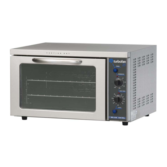
- Page 1 E25 CONVECTION OVEN E25MS CONVECTION OVEN SERVICE MANUAL E25 Convection Oven © Moffat Ltd, August 2006 Revision 6/F3501...
- Page 2 WARNING: ALL INSTALLATION AND SERVICE REPAIR WORK MUST BE CARRIED OUT BY QUALIFIED PERSONS ONLY. E25 Convection Oven © Moffat Ltd, August 2006 Revision 6/F3501...
-
Page 3: Table Of Contents
CONTENTS This manual is designed to take a more in depth look at the E25 convection oven for the purpose of making the unit more understandable to service people. There are settings explained in this manual that should never require to be adjusted, but for completeness and those special cases where these settings are required to change, this manual gives a full explanation as to how, and what effects will result. - Page 4 PARTS DIAGRAM ......................38 11.1 Main Assembly - E25 11.2 Main Assembly - E25B 11.3.1 Control Panel Assembly - E25 11.3.2 Control Panel Assembly - E25B 11.4.1 Control Panel Assembly - E25MS 11.4.2 Control Panel Assembly - E25BMS 11.5 Door Assembly - E25MS SERVICE CONTACTS....................
-
Page 5: Specifications
1. SPECIFICATIONS MODEL: E25 / E25B (28.4) (23.6) (1.9) (24.6) (1.75) (4.9) (15.5) (4.4) FRONT SIDE PLAN LEGEND - Electrical connection entry point Dimensions shown in millimetres. Dimensions in inches shown in brackets. E25 Convection Oven © Moffat Ltd, August 2006... - Page 6 3-pin 120V 15A, NEMA 6-15 Other Countries 3-pin 250V 10A minimum, type to meet country standards E25B Canada 3-pin 120V 20A, NEMA 6-20 United States 3-pin 120V 20A, NEMA 6-20 E25 Convection Oven © Moffat Ltd, August 2006 Revision 6/F3501...
-
Page 7: Installation
RATING PLATE LOCATION installation clearances are to be adhered to: The rating plate for the E25 convection oven is located at the bottom left corner of the RH 200mm / 8” side panel. Rear 25mm / 1”... -
Page 8: Operation
3. OPERATION NOTE: A full user’s operation manual is supplied with the product and can be used for further referencing of installation, operation and service. 3.1 DESCRIPTION OF CONTROLS - E25 1. POWER Depress to switch power on or off (switch illuminates when power is on). -
Page 9: Description Of Controls-E25B
3. BAKE TIMER 1 Hour bake timer. (Indicator illuminates when “time up” (0) reached, and buzzer sounds). 4. LIGHT SWITCH Push switch to activate light. (Oven light illuminates while button depressed). E25 Convection Oven © Moffat Ltd, August 2006 Revision 6/F3501... -
Page 10: Explanation Of Control System
The E25 and E25B Turbofan convection ovens feature multi-function operator controls The E25 has an element coiled around the for which a correct understanding of their circulation fan in the rear of the oven. Power... - Page 11 Troubleshooting Guide will make reference to the corrective action required, or refer to the Fault Diagnosis section and/or Service section to assist in correction of the fault. E25 Convection Oven © Moffat Ltd, August 2006 -11- Revision 6/F3501...
-
Page 12: Maintenance
Lift baffle out from rear of oven by tilting forward while lifting out of location studs at baffle base. Replace in reverse order. E25 Convection Oven © Moffat Ltd, August 2006 -12- Revision 6/F3501... -
Page 13: Trouble Shooting Guide
For timer settings below 20 min- INACCURATE BELOW 20 utes, always rotate past 20 min- MINUTES utes, then back to desired time. Zero (time up) position not set (Refer service section 6.4.4) correctly. E25 Convection Oven © Moffat Ltd, August 2006 -13- Revision 6/F3501... - Page 14 Broil relay faulty - E25B only. Replace. (Refer fault diagnosis 6.1.10) (Refer service section 6.3.8) NO THERMOSTAT HEATING Indicator faulty. Replace. INDICATOR LIGHT (Refer fault diagnosis 6.1.11) (Refer service section 6.3.3) E25 Convection Oven © Moffat Ltd, August 2006 -14- Revision 6/F3501...
- Page 15 (Refer service section 6.3.4) Broil relay faulty (E25B only). Replace. (Refer fault diagnosis 6.1.15) (Refer service section 6.3.8) Heating relay faulty (E25B Replace. only). (Refer service section 6.3.8) (Refer fault diagnosis 6.1.15) E25 Convection Oven © Moffat Ltd, August 2006 -15- Revision 6/F3501...
-
Page 16: Service Procedures
Power Switch Does Not Turn Unit Off ..............21 ACCESS ..........................22 6.2.1 Control Panel .......................22 6.2.2 Service Panel (Rear Panel) .................22 6.2.3 Baffle ........................22 6.2.4 E25 Control Panel (Rear)..................22 6.2.5 E25B Control Panel (Rear) ..................22 REPLACEMENT........................23 6.3.1 Light Bulb / Glass....................23 6.3.2 Door Microswitch ....................23 6.3.3 Indicator Neon Light.....................23... - Page 17 ADJUSTMENT / CALIBRATION ..................28 6.4.1 Thermostat Calibration (E25)................28 6.4.2 Thermostat Calibration (E25B) ................28 6.4.3 Door Microswitch Adjustment ................29 6.4.4 60 Minute Timer Zero Position Adjustment............29 E25 Convection Oven © Moffat Ltd, August 2006 -17- Revision 6/F3501...
-
Page 18: Fault Diagnosis
If voltage is correct then the com terminal and the n.c. terminal. buzzer is faulty—replace. If not, microswitch is faulty—replace. If there is no voltage, then check wiring. E25 Convection Oven © Moffat Ltd, August 2006 -18- Revision 6/F3501... -
Page 19: Minute Timer No Time Up Indicator
Indicator faulty replace. With the timer in the zero position, check for NOTE: E25 thermostat may cycle on and off voltage across the indicator light. If correct, with the knob set to the ‘off’ position if the then the indicator light is faulty—replace. -
Page 20: Fan Element Not Working
With the thermostat on and heating, check the voltage across the indicator terminals. If the voltage is correct then the indicator is faulty— replace. If there is no voltage then check wiring. E25 Convection Oven © Moffat Ltd, August 2006 -20- Revision 6/F3501... -
Page 21: Broil Indicator Not Working
With the oven switched off, disconnect the wires from terminals 9 and 6 of the heating relay. Check for continuity through these terminals. If there is continuity then the relay is faulty—replace. E25 Convection Oven © Moffat Ltd, August 2006 -21- Revision 6/F3501... -
Page 22: Access
6.2 ACCESS 6.2.4 E25 CONTROL PANEL—REAR 6.2.1 CONTROL PANEL 1) Undo one screw at bottom of control panel. Power Switch Heating Indicator Thermostat Bake Time Up One Screw Bake Timer Figure 6.2.1 2) Pull out bottom of control panel and drop down to disengage tabs at top of control panel. -
Page 23: Replacement
1) With control panel open (refer 6.2.1) Two Screws remove the wires from the back of the neon. Figure 6.3.5 4) Transfer wires to new buzzer. 5) Reassemble in reverse order. E25 Convection Oven © Moffat Ltd, August 2006 -23- Revision 6/F3501... -
Page 24: Bake Timer
4) Replace and re-assemble in reverse order. Element Ratings 100-120V Top Element 7.2 ohms Fan Element (E25) 9.3 ohms Screws Fan Element (E25B) 7.2 ohms Figure 6.3.8 220-240V Fan Element 28.8 ohms E25 Convection Oven © Moffat Ltd, August 2006 -24- Revision 6/F3501... -
Page 25: Fan
Reassemble with one washer behind fan, and one washer in front. Figure 6.3.14 6.3.11 MOTOR 6.3.12 OUTER GLASS ( E25 / E25B) 1) Remove fan (refer 6.3.10), remove service panel (refer 6.2.2) and then remove the 1) Open the oven door. -
Page 26: Inner Glass
Clean the inside of the glass and refit it, ensuring that the silicone rubber seals 6.3.15 DOOR HANDLE (E25 / E25B) cover the outer edges of the glass. Refit 1) Remove the door (refer 6.3.12). - Page 27 Re-assemble in reverse order. Figure 6.3.23 7) Remove wrapper. 8) Undo two screws securing left hand counter bracket to oven and remove. Replace, ensuring that bracket is installed with roller to top. E25 Convection Oven © Moffat Ltd, August 2006 -27- Revision 6/F3501...
-
Page 28: Adjustment / Calibration
6.4 ADJUSTMENT / CALIBRATION 6.4.2 THERMOSTAT CALIBRATION - E25B 6.4.1 THERMOSTAT CALIBRATION - E25 IMPORTANT: OVEN T E M P E R A T U R E N E E D S IMPORTANT: OVEN INCREASED, ENSURE THAT T E M P E R A T U R E N E E D S THERMOSTAT IS IN THE ‘OFF’... -
Page 29: Door Microswitch Adjustment
1) Open oven door. 2) Open control panel (refer 6.2.1). 3) With fingers, bend actuator arm of microswitch so that switch operates when door is in closed position. Actuator Arm Figure 6.4.6 E25 Convection Oven © Moffat Ltd, August 2006 -29- Revision 6/F3501... -
Page 30: Electrical Schematics
7. ELECTRICAL CIRCUIT SCHEMATIC 7.1 E25 E25 Convection Oven © Moffat Ltd, August 2006 -30- Revision 6/F3501... -
Page 31: E25B
7.2 E25B E25 Convection Oven © Moffat Ltd, August 2006 -31- Revision 6/F3501... -
Page 32: Electrical Wiring Diagrams
8. ELECTRICAL WIRING DIAGRAM 8.1 E25 (220 - 240V) 8.1.1 E25 (220-240V) -From S/N 251948 E25 Convection Oven © Moffat Ltd, August 2006 -32- Revision 6/F3501... - Page 33 8.1.2 E25 (220-240V) -To S/N 251947 E25 Convection Oven © Moffat Ltd, August 2006 -33- Revision 6/F3501...
-
Page 34: E25 (110V)
8.2 E25 (110V) E25 Convection Oven © Moffat Ltd, August 2006 -34- Revision 6/F3501... -
Page 35: E25B
8.3 E25B E25 Convection Oven © Moffat Ltd, August 2006 -35- Revision 6/F3501... -
Page 36: Spare Parts
Oven Lamp (220-240V) 40W Miniature Edison Screw --------- Oven Lamp (110V) 40W Edison Screw MOTOR & ELEMENTS 023071 Oven Fan Element (E25 only) (240 volt) 023069 Oven Fan Element (E25 only) (110 volt) 023072 Oven Top Element (E25B only) (110 volt) - Page 37 OVEN RACKS (PART NO 12809) (PART NO 13048) 25 MM (ONE INCH) FOOT OPTION (PART NO 13908) SCONE TRAYS (PART NO 02083) DOUBLE STACKING KIT (PART NO 24290) A25 STAINLESS STEEL STAND E25 Convection Oven © Moffat Ltd, August 2006 -37- Revision 6/F3501...
- Page 38 11. PARTS DIAGRAMS 11.1 MAIN ASSEMBLY - E25 E25 Convection Oven © Moffat Ltd, August 2006 -38- Revision 6/F3501...
- Page 39 Part No. Description 012809 OVEN RACK 011402 PIVOT TOP COVER - E25 / E25B 005040 PIVOT TOP COVER - E25MS / E25BMS 023074 LINTEL SUPPORT 023087 WRAPPER 022042 003016 MOTOR PLATE 013431K MOTOR - 240V (From S/N 251948) 023215 MOTOR – 240V (Up to S/N 251947) 025387 MOTOR –...
- Page 40 11.2 MAIN ASSEMBLY - E25B (110V ONLY) E25 Convection Oven © Moffat Ltd, August 2006 -40- Revision 6/F3501...
- Page 41 Part No. Description 012809 OVEN RACK 011402 PIVOT TOP COVER - E25 / E25B 005040 PIVOT TOP COVER - E25MS / E25BMS 023074 LINTEL SUPPORT 023087 WRAPPER 022042 003016 MOTOR PLATE 025387 MOTOR (110V) 023075 OVEN 017770 PHIAL GUARD 023093...
- Page 42 11.3.1 CONTROL PANEL ASSEMBLY - E25 Part No. Description 004851 CONTROL PANEL - BAKBAR 004880 CONTROL PANEL - BLUE SEAL 004850 CONTROL PANEL - MOFFAT 021473 POWER SWITCH – 240V 021514 POWER SWITCH – 110V 020849 NEON INDICATOR - 240V...
- Page 43 023857 NEON - 110V 020823 KNOB 021474 LIGHT SWITCH 015822 BUZZER - 110V 023212 TIMER - COUPATAN (TO S/N 228661) 011760 TIMER - DIEHL (FROM S/N 228662) 017121 THERMOSTAT E25 Convection Oven © Moffat Ltd, August 2006 -43- Revision 6/F3501...
- Page 44 KNOB -THERMOSTAT 011760 1 HOUR TIMER 020823 KNOB TIMER 021474 LIGHT SWITCH 015822 BUZZER - 110V 011794 BUZZER - 240V 026495 OVERLAY - MOFFAT 026608 OVERLAY - BLUE SEAL E25 Convection Oven © Moffat Ltd, August 2006 -44- Revision 6/F3501...
- Page 45 POWER SWITCH - 110V 023857 NEON INDICATOR - 110V 023211 THERMOSTAT 021472 KNOB -THERMOSTAT 011760 1 HOUR TIMER 021474 LIGHT SWITCH 015822 BUZZER - 120 026609 OVERLAY - MOFFAT E25 Convection Oven © Moffat Ltd, August 2006 -45- Revision 6/F3501...
- Page 46 DOOR INNER WA 023217 HINGE 026485 DOOR OUTER PANEL WA 026578 HANDLE STIFFENER 026498 DOOR HANDLE PLATED 023063 DOOR INNER GLASS 023228 INNER GLASS SEAL 026491 GLASS CLAMP ANGLE E25 Convection Oven © Moffat Ltd, August 2006 -46- Revision 6/F3501...
- Page 47 Mulgrave VIC 3170 Fax (03) 9518 3838 Spare Parts Department Free Call 1800 337 963 Fax (03) 9518 3895 NEW SOUTH WALES - MOFFAT PTY Unit 3/142 James Ruse Drive Tel (02) 8833 4111 Rosehill NSW 2142 Spare Parts Free Call 1800 337 963...
- Page 48 UNITED STATES OF AMERICA MOFFAT INC. 3765 Champion Blvd Winston-Salem Tel 1-800-551 8795 NC27115 Fax 336 661 9546 NATIONAL COVERAGE FOR SERVICE OR MAINTENANCE DIAL FREE CALL 1800 551 8795 (USA ONLY) E25 Convection Oven © Moffat Ltd, August 2006 -48- Revision 6/F3501...
- Page 49 (with fibre washers). Secure to bottom of oven with three screws. Secure the double stack rear to the double stack sides with two screws. E25 Convection Oven © Moffat Ltd, August 2006 -49- Revision 6/F3501...
- Page 50 Hold rear cover panel against rear of top unit and check the position of the marked notches against the vent pipe. Cut out the notches and refit the rear panel.) Figure A.2 E25 Convection Oven © Moffat Ltd, August 2006 -50- Revision 6/F3501...
- Page 51 E25 Convection Oven -51- © Moffat Ltd, August 2006 Revision 6/F3501...