Moffat E35 Installation & Operation Manual
Hide thumbs
Also See for E35:
- Brochure & specs (2 pages) ,
- Service manual (67 pages) ,
- Specifications (20 pages)
Table of Contents
Advertisement
Advertisement
Table of Contents

Related Manuals for Moffat E35


Summary of Contents for Moffat E35
- Page 1 INSTALLATION / OPERATION MANUAL E35 CONVECTION OVEN 232109-4...
- Page 2 The reproduction or copying of any part of this manual by any means whatsoever is strictly forbidden unless authorized previously in writing by the manufacturer. In line with policy to continually develop and improve its products, Moffat Ltd. reserves the right to change the specifications and design without prior notice.
-
Page 3: Table Of Contents
Contents Introduction ......................2 Installation ......................3 Installation Requirements Before Connection to Power Supply Location Bench Mounting Floor Mounting Stand Mounting Electrical Connection Water Connection Before Use Specifications ....................5 Operation......................6 Description of Controls Baking Door Handle Oven Side Racks Removal of Side Racks Replacement of Side Racks Cleaning...................... -
Page 4: Introduction
Please read the instruction book carefully and follow the directions given. The time taken will be well spent. Secondly If you are unsure of any aspect of the installation, instructions or performance of your oven, contact your E35 dealer promptly. In many cases a phone call could answer your question. -
Page 5: Installation
Check that the available power supply is correct to that shown on the rating plate located on the right-hand side panel. Model Electrical Rating E35-xx-251 230-240 V a.c., 50 Hz, 1P+N+E, 12.5 kW @ 240 V E35-xx-P251 208-220 V a.c., 50 Hz, 1P+N+E, 12.5 kW @ 220 V E35-xx-P253 208-220 V a.c., 50 Hz, 3P+E, 12.5 kW @ 220 V... -
Page 6: Bench Mounting
For floor mounted applications the oven must be fitted with 150mm / 6inch legs. NOTE: Four 100 mm / 4 inch adjustable or 150 mm / 6 inch legs are available separately from your E35 dealer as an optional extra. Stand Mounting •... -
Page 7: Specifications
Specifications E35 Specifications 34 5 8 " 34 5 8 " 3 1 8 " 6 1 2 " ” WATER ENTRY 28 3 8 " 26 1 4 " 1 7 8 " ELECTRICAL ENTRY FRONT SIDE VENT Ø 76 O.D. -
Page 8: Operation
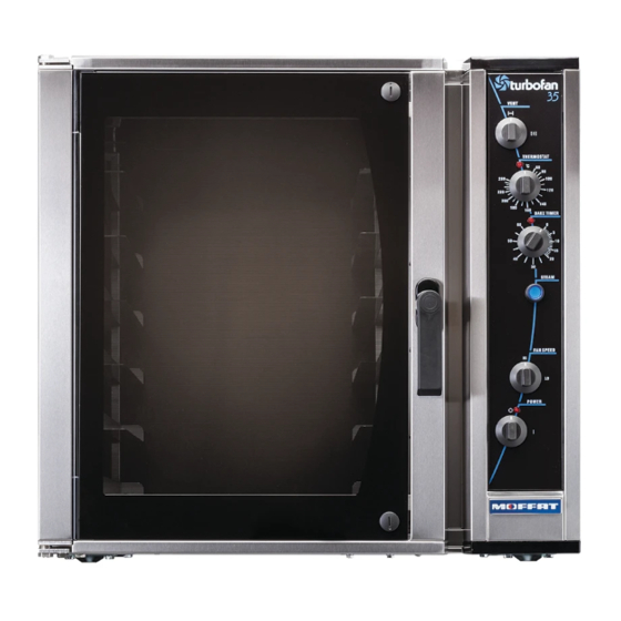
Operation Description of Controls Vent Vent closed with switch in the vertical position. Vent open with switch in the horizontal position. °C Thermostat Temperature range 100 - 550°F (60-280°C). Indicator illuminates when the elements are cycling ON to maintain set temperature. Bake Timer 1 Hour bake timer. -
Page 9: Baking
Operation Baking 1. Turn Power 'On' The indicator light will illuminate whenever the switch is in the “I” (On) position (the oven lights will also illuminate). The oven fan will start after 10 seconds with the door closed. The fan delay will repeat when- ever the door is closed after opening. -
Page 10: Door Handle
Operation Baking 8. Time Up When the timer reaches 0 minutes the buzzer will sound, and the indicator illuminates. To cancel the buzzer turn the timer to the off position. 9. Unload Oven Open the door and unload the oven . The oven fan will stop when the door is opened. -
Page 11: Removal Of Side Racks
Operation Side Racks 16 inch tray 1. The side racks can be fitted in one of two locator positions, in order to take 16 or 18 inch trays. 2. To position racks for 16 inch trays, use the holes at the rear of the rack. 3. -
Page 12: Cleaning
Cleaning Cleaning Guidelines AUTIO N ALWAYS TURN OFF THE POWER SUPPLY BEFORE CLEANING. THIS UNIT IS NOT WATER PROOF. DO NOT USE WATER JET SPRAY TO CLEAN INTERIOR OR EXTERIOR OF THIS UNIT. Exterior Clean with a good quality stainless steel cleaning compound. Harsh abrasive cleaners may damage the surface. -
Page 13: Faultfinding
Fault Finding A U T I O N This appliance is; • For professional use and is to be used by qualified persons only. • Only authorised service persons are to carry out installation, and servicing operations. • Components having adjustments protected (e.g. paint sealed) by the manufacturer should not be adjusted by the user / operator. -
Page 14: Circuit Schematics
Circuit Schematic 208V-220V, 3P+E 230-240V, 3P+E... - Page 15 Circuit Schematic 208-220V, 1P+N+E 230-240V, 1P+N+E...
- Page 16 Circuit Schematic 380V, 3P+N+E 400-415V, 3P+N+E...
-
Page 17: Replacement Parts List
231764 Solid State Thermostat. 020883K Thermostat Probe. 020823 Control Panel Knobs. Gear Plate 231740 Heating Contactor E35-xx-x253 / 263 (3P+E) Models Only. 231739 Heating Contactor 1P+N+E & 3P+N+E Models. 231741 Motor Contactor. 231742 Motor Contactor 1 Phase Models Only. 231743 Contactor Interlock 3 Phase Models Only. - Page 18 Rack Runner 8 Tray LH WA (E35-26”). 025090 Rack Runner 8 Tray RH WA (E35-26”). 023118 Side Rack L / Hand WA 8 Tray (E35-30”). 023119 Side Rack R / Hand WA 8 Tray (E35-30”). 026590 Rack Runner 4 Tray L / Hand WA (E35-30”).