Salus VS20WRF Installer's/User's Manual
4 in 1 digital thermostat rf
Hide thumbs
Also See for VS20WRF:
- Installer's/user's manual (96 pages) ,
- User manual (93 pages) ,
- Full user manual (74 pages)

Related Manuals for Salus VS20WRF


Summary of Contents for Salus VS20WRF
- Page 1 4 in 1 Digital Thermostat RF Models: VS20WRF and VS20BRF VS10WRF and VS10BRF I N S T A L L E R / U S E R M A N U A L VS20WRF and VS20BRF Installer Manual...
-
Page 2: Table Of Contents
Introduction Product Compliance System options overview Important info Installation Parameter Settings Your benefit Error Codes User Guide Installers notes Warranty Box Contents 4x AAA Batteries VS10RF VS20RF Fixing screws 1 x Installer / User manual VS20WRF and VS20BRF Installer Manual... - Page 3 Product Compliance & Safety Information INTRODUCTION Safety Information Thank you for purchasing the SALUS 4 in 1 room Use in accordance with the regulations. The thermostat. It must be used with the UG600/ SALUS VS10RF/VS20RF is to be used for room UGE600 or with the CO10RF Zigbee Coordinator.
-
Page 4: Product Compliance
Installer parameter settings Warning The SALUS VS20 are equipped with installer parameter section (see page 71) this must only be entered by Always isolate the AC Main supply before the installer or competent person. Changing these... - Page 5 Thermostat (PRT) Wiring Centre Group Control UFH Manifold Thermostat* Radiator Boiler Group Thermostat* Hot Water Timer Towel Rails * Grouping and timer option only available when used with wiring centre. VS20WRF and VS20BRF Installer Manual...
- Page 6 When configured to timer the unit will operate as a timer with no temp control. This can be used for hot water control. The timer will also follow Holiday mode from the group control thermostat if applicable. VS20WRF and VS20BRF Installer Manual...
- Page 7 System Overview - Zigbee Coordinator Zigbee coordinator required for communication between these devices. KL08RF VS20RF UG600/UGE600 RX10RF TRV10RFM CO10RF VS20WRF and VS20BRF Installer Manual...
- Page 8 System Overview - Salus SmartHome System The thermostat can communicate with all these Salus SmartHome devices. KL08RF or KL08NSB can be used System Receiver configured to one room receiver RX2. Refer to system UNDERFLOOR HEATING MANIFOLD receiver RX10RF. System Receiver configured to boiler receiver.
- Page 9 When the unit is configured as a hot water timer (see page 32) there are two methods of connecting the cylinder thermostat. Unit configured to Hot Water Timer. Cylinder thermostat options Connected direct to WC (Default) Connected direct to VS20RF (requires additional parameter change. See page 71) VS20WRF and VS20BRF Installer Manual...
- Page 10 HW Timer or Wiring Centre. Connected direct to WC (Default) Connected direct to VS20RF (requires additional parameter change see page 32) Please refer to Wiring Centre guide and pages 15, 20 for more information. VS20WRF and VS20BRF Installer Manual...
- Page 11 · · Not to be positioned on exterio · · Do not install the remote senso · · Only the temperature at the po · · Not to be positioned on an exterior wall. VS20WRF and VS20BRF Installer Manual 130cm...
- Page 12 Installation – Thermostat Mounting VS20WRF 60mm Carefully remove the front housing. VS20WRF and VS20BRF Installer Manual...
- Page 13 Installation – Terminal Connections VS20WRF Understanding your terminal connections Rear of unit Sensor Terminals Can be used for external AIR, Floor sensor when configured as thermostat. Can also be used for Cylinder thermostat when configured for HW. See page 71.
- Page 14 Installation – Thermostat External Sensor VS20WRF SALUS External sensor (Sold separately) Note: If you are using an external sensor, the unit has to be configured for External Air Sensor or Floor Protection Sensor please see device parameter setting page 71.
- Page 15 Installation – Hot Water Timer Cylinder Thermostat VS20WRF 5 x 20mm 5 x 20mm 5 x 20mm 5 x 20mm SL N L SL N L SL N L SL N L SL N L SL N L SL N L...
- Page 16 Installation – Thermostat Mounting VS20WRF Once you have connected your choice of external sensor (if applicable) Insert batteries VS20WRF and VS20BRF Installer Manual...
- Page 17 Installation – Thermostat Mounting VS10WRF 60mm Carefully remove the front housing. VS20WRF and VS20BRF Installer Manual...
- Page 18 Sensor Terminals Can be used for external AIR, Floor sensor when configured as thermostat. Can also be used for Cylinder thermostat when configured for HW. VS20WRF and VS20BRF Installer Manual...
- Page 19 Installation – Thermostat External Sensor VS10WRF SALUS External sensor (Sold separately) Note: If you are using an external sensor, the unit has to be configured for External Air Sensor or Floor Protection Sensor please see device parameter setting page 71. VS20WRF and VS20BRF Installer Manual...
- Page 20 Note: The unit can be configured for Cylinder thermostat or connected to the Hot Water Timer. Please see device parameters page 71. For additional Wiring Centre information refer to note 1 on Wiring Centre guide. VS20WRF and VS20BRF Installer Manual...
- Page 21 Check that the wiring is completed for: Power Terminals Sensor Terminals (if applicable) You are ready to secure the rear housing to the wall box Please use the screws provided Ensure the orientation arrow is pointing upwards. VS20WRF and VS20BRF Installer Manual...
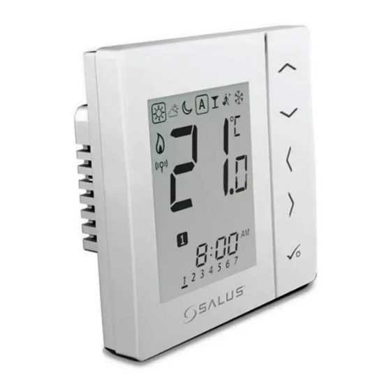
- Page 22 When Vacation mode is active Frost protection indicator: Frost protection is active, not available in cooling mode (if applicable) RF Transmission is active Group 1 Control Thermostat Group 2 Control Thermostat Group 1 Thermostat Group 2 Thermostat VS20WRF and VS20BRF Installer Manual...
- Page 23 If the set temperature is changed when in program mode, the hand will appear until the next program start time. Programs number indicator: In AUTO program mode or Temporary override is running, it means the current program running. Day indication: 1 = Monday VS20WRF and VS20BRF Installer Manual...
- Page 24 Mode for 1 period of HW a day, from Program 1 ON to Program 3 OFF. HW Mode indicator: Indicates continuously On. HW Mode indicator: Indicates continuously Off. HW Mode indicator: Indicates Boost +1hr override. VS20WRF and VS20BRF Installer Manual...
- Page 25 Indicates that heating of the zone has been halted to protect the floor from over-heating. Low battery indicator: Batteries need to be replaced. Setting indicator: Indicate the unit is in setting mode when program setting. Indicate the manual mode. Keylock indicator: Shows that keys are inactive. VS20WRF and VS20BRF Installer Manual...
- Page 26 1. OK key: Short press to confirm selection. 2. Long press to save and exit. 3. Long press to enter the user settings. Lock/Unlock LONG PRESS Enter Installer parameter settings LONG PRESS VS20WRF and VS20BRF Installer Manual...
- Page 27 Installation - Graphics Key Press once Press x amount of times Hold for five seconds Flashing Short press to save and Short press to back up long press to save and exit VS20WRF and VS20BRF Installer Manual...
- Page 28 Installation – First Power Up The following screens show examples only MCU software version will be shown *Please note that 88.8 and 8.8 are a reference to the software version. ZIGBEE software version will be shown VS20WRF and VS20BRF Installer Manual...
- Page 29 * The coordinator will be used only for the underfloor systems that are not connected via the gateway. The device that you intend to pair with must be ready to accept pairing. Please refer to pages 33-52 and the relevant device installation guides. VS20WRF and VS20BRF Installer Manual...
- Page 30 Salus Wiring Centre* within the Salus SmartHome? Salus radiator valve *If you have made an error please go to page 71. You will see the to select the type of following screen. unit to pair with. VS20WRF and VS20BRF Installer Manual...
- Page 31 Installation – System Parameters If the pre-configured program is not suitable for your application, hold down the bottom three keys for a short time, until the display shows SEL PROG. VS20WRF and VS20BRF Installer Manual...
- Page 32 Selecting what unit to pair with Wiring Centre. Page 33 Radiator Valve. Page 38 System Receiver Configured RX2. Page 45 to select the type of System Receiver unit to pair with. Only configure RX1. Page 49 VS20WRF and VS20BRF Installer Manual...
- Page 33 Red LED on RX1 will go steady when the devices have joined the Zigbee network. If more than one wiring centre is in the system, establish and note the wiring centre number by pressing the pair key for 1 second. The wiring centre number will flash. VS20WRF and VS20BRF Installer Manual...
- Page 34 App. The gateway will start flashing red. After you have put your coordinator or gateway in pair mode, please follow the steps below on the thermostat in order to finalize the pairing process. VS20WRF and VS20BRF Installer Manual...
- Page 35 If you are using groups, use to select group number of each group required. If unit is stand alone then please select -- Group 1 Group 2 VS20WRF and VS20BRF Installer Manual...
- Page 36 Installation - Pairing with Wiring Centre select the wiring centre zone number 1 to 8. If you add a KL04RF to your KL08RF you will be able to add up to 12 zones. Zone number VS20WRF and VS20BRF Installer Manual...
- Page 37 UNDERFLOOR HEATING MANIFOLD green light goes on when the temperature is raised and off when reduced. The boiler SUPPLIED CABLES and the pump have the ON/OFF Delay function. For more details please see the KL08RF manual. VS20WRF and VS20BRF Installer Manual...
- Page 38 Please pair TRVs on a room by room basis. If you are using the optional system receiver configured to RX1 for remote boiler switching, ensure this has been powered up and the red flashing LED has gone steady. VS20WRF and VS20BRF Installer Manual...
- Page 39 App. The gateway will start flashing red. After you have put your coordinator or gateway in pair mode, please follow the steps below on the thermostat in order to finalize the pairing process. VS20WRF and VS20BRF Installer Manual...
- Page 40 Installation - Pairing the Radiator Valve(s) Associate the TRV with the thermostat Tap the thermostat icon Tap the name of the thermostat VS20WRF and VS20BRF Installer Manual...
- Page 41 Installation - Pairing the Radiator Valve(s) VS20 Tap the Edit button Select the TRV and tap Save to confirm. Note: The association is needed only for the systems that are using an Universal Gateway with Internet connection. VS20WRF and VS20BRF Installer Manual...
- Page 42 Installation - Pairing with Radiator Valve Tap to start the pairing process. VS20WRF and VS20BRF Installer Manual...
- Page 43 The pre fix number on the TRV will change as the TRV(s) pair. Once all TRV’s have paired press If you use the maximum number of TRVs it will automatically take you to the Mainscreen. VS20WRF and VS20BRF Installer Manual...
- Page 44 If you are using the optional system receiver configured to RX1 please check that the green light goes on when the temperature is raised and off when reduced. For more details please see the RX10RF manual. VS20WRF and VS20BRF Installer Manual...
- Page 45 Refer to RX10RF manual. If you are using the optional system receiver configured to RX1 for remote boiler switching. Ensure this has been powered up and the red flashing LED has gone steady. Refer to RX10RF manual. VS20WRF and VS20BRF Installer Manual...
- Page 46 App. The gateway will start flashing red. After you have put your coordinator or gateway in pair mode, please follow the steps below on the thermostat in order to finalize the pairing process. VS20WRF and VS20BRF Installer Manual...
- Page 47 Installation - Pairing with System Receiver RX2 VS20WRF and VS20BRF Installer Manual...
- Page 48 Green LED on receiver configured to RX1 please check that the green light goes on when the temperature decrease temperature to raised 10ºC and then when reduced. press Green LED off VS20WRF and VS20BRF Installer Manual...
- Page 49 The system receiver (Configured to RX1) is powered up and the red LED will flash when the pairing is in process and will be steady when the pairing is complete. Used when you want multiple thermostats to activate the same receiver VS20WRF and VS20BRF Installer Manual...
- Page 50 App. The gateway will start flashing red. After you have put your coordinator or gateway in pair mode, please follow the steps below on the thermostat in order to finalize the pairing process. VS20WRF and VS20BRF Installer Manual...
- Page 51 Installation - Pairing with System Receiver RX1 only VS20WRF and VS20BRF Installer Manual...
- Page 52 Green LED off 5 sec If pairing for your system is complete, please take the 5 sec coordinator or the universal gateway out of pair mode. Press for 5 seconds and light will stop flashing. VS20WRF and VS20BRF Installer Manual...
- Page 53 SALUS SmartHome product. For systems without the SALUS RX10RF boiler receiver Adaptive Learning Mode will start automatically. When Adaptive Learning Mode is...
- Page 54 Changing Control Method. Calibration Procedure Using the SALUS SmartHome App Insert the password (49) and press OK to confirm. VS20WRF and VS20BRF Installer Manual...
- Page 55 To exit to the Dashboard, press on the SALUS logo on top of the screen. To exit to the Dashboard, press on the SALUS logo on top of the screen VS20WRF and VS20BRF Installer Manual...
- Page 56 Changing Control Method Continued Calibration Procedure Manually - with Internet connection Select required option Standard On/ Auto Advanced self Off control Selection learning control VS20WRF and VS20BRF Installer Manual...
- Page 57 Calibration Procedure For Auto-Selection press to confirm Press for CAL 0 and to confirm Press for CAL 2 and to confirm Advanced self Standard On/OFF control learning control VS20WRF and VS20BRF Installer Manual...
- Page 58 Calibration Procedure Manually - without Internet connection Select required option Standard On/ Auto Advanced self Off control Selection learning control VS20WRF and VS20BRF Installer Manual...
- Page 59 Calibration Procedure For Auto-Selection press to confirm Press for CAL 0 and to confirm Press for CAL 2 and to confirm Advanced self learning control Standard On/OFF control VS20WRF and VS20BRF Installer Manual...
- Page 60 Installation - Modifying System Parameters If you have made an error or need to change your system parameters please follow steps below. This should only be done by your installer. Press all three buttons simultaneously VS20WRF and VS20BRF Installer Manual...
- Page 61 Installation - Modifying System Parameters Unit will follow power up sequence on page 28. You are now ready to enter or change your system parameters. Refer to page 29. VS20WRF and VS20BRF Installer Manual...
- Page 62 Press again for 1 Press for 1 second to cancel second identify. Identify to activate mode will time out identify mode. after 10 minutes. The LEDs are different on the KL08RF wiring centre. VS20WRF and VS20BRF Installer Manual...
- Page 63 If you want to see what devices are connected to your Universal Gateway you can know exactly by using the Identify procedure. Start the Identify Process Tap the tile from the Dashboard. Tap the name of your device. VS20WRF and VS20BRF Installer Manual...
- Page 64 If you want to see what devices are connected to your Universal Gateway you can know exactly by using the Identify procedure. End the Identify Process Tap the Identify button. Your device will start flashing Tap the button again after identifying your device. VS20WRF and VS20BRF Installer Manual...
- Page 65 When in identify mode all receivers configured correctly, you can use and the coordinator related to the identify mode. individual PRT will flash. Press tick to cancel identify. Identify mode will time out after 10 minutes. System has no grouping VS20WRF and VS20BRF Installer Manual...
- Page 66 Press tick to cancel identify. Identify mode will time out after 10 minutes. Group Control Thermostat System has grouping Group Control Group Group Group Thermostat Thermostat Thermostat Thermostat VS20WRF and VS20BRF Installer Manual...
- Page 67 Then wiring centre identify mode. number will also be shown. Press again for 5 Press for second to cancel 5 second identify. Identify to activate mode will time out identify mode. after 10 minutes. VS20WRF and VS20BRF Installer Manual...
- Page 68 PRT will flash. Press tick to cancel identify. Identify mode will time out after 10 minutes. System has no grouping VS20WRF and VS20BRF Installer Manual...
- Page 69 If the wiring centre cannot be deleted as above, use the method below. You are now Please follow step 1 ready to on page 71. Select install your password 46. new wiring centre. VS20WRF and VS20BRF Installer Manual...
- Page 70 71. Select that are offline. password 48. Note: If replacing a thermostat connected to the wiring centre, you can use the replacement method. The unit previously connected to the wiring centre will be replaced. VS20WRF and VS20BRF Installer Manual...
- Page 71 Installation - Modifying Device Parameters If you have made an error or need to change your system parameters please follow steps below. This should only be done by your installer. Press all three buttons simultaneously VS20WRF and VS20BRF Installer Manual...
- Page 72 When connected to the internet you can access them directly from the App. Press repeatedly until you reach the d01 screen. *Please note that x=1,2, 3 or any °C value. Note: You can see the Installer Mode Parameters on page 73 in the Manual. VS20WRF and VS20BRF Installer Manual...
- Page 73 On-Off 0.5 Deg C +/- 0.25 Deg C On-Off 1.0 Deg C +/- 0.5 Deg C Actuator type NO Normally Open NC Normally Closed * When thermostat is paired with TRV then D01 default will be “1” VS20WRF and VS20BRF Installer Manual...
- Page 74 6-40 Deg C when temp is reached for 10 Deg C floor protection Floor sensor Limit Output relay will be switched off for cooling 6-40 Deg C when temp is reached for 6 Deg C floor protection VS20WRF and VS20BRF Installer Manual...
-
Page 75: Error Codes
Press Up again to show Err 03 09 ===> 3 errors Error code 09 ( 3rd one ) Press Up again to show Err 03 05 again..Press OK to exit Error page back to Home display. VS20WRF and VS20BRF Installer Manual... - Page 76 (Displayed on all connected thermostats) thermostats) TRV low battery TRV low battery (Displayed on all connected (Displayed on all connected thermostats) thermostats) Invalid TRV Invalid TRV Unit is rejected by wiring centre Unit is rejected by wiring centre VS20WRF and VS20BRF Installer Manual...
- Page 77 WC lost link with zone 12 prog/ WC lost link with zone 12 prog/ non-prog thermostat (displayed non-prog thermostat (displayed on all connected thermostats) on all connected thermostats) VS20WRF and VS20BRF Installer Manual...
- Page 78 TRV adaptation issue Reserved for future use Reserved for future use Reserved for future use Receiver lost link with devices Receiver lost link with devices Receiver lost link with devices Error 33 is displayed in the app. VS20WRF and VS20BRF Installer Manual...
- Page 79 Global changeover using communication bus and external input to the wiring centre Sensor Air or floor protection. Cylinder thermostat when configured for hot water timer. Device Parameters See page 71 Operating Temperature 0 to 45ºC Storage Temperature -20 to 60ºC Frequency 2.4GHz Zigbee VS20WRF and VS20BRF Installer Manual...
- Page 80 User Guide - Setting time and date Note: Time and date will be set automatically for the systems connected to the Internet PRT and Group Control Thermostat VS20WRF and VS20BRF Installer Manual...
- Page 81 User Guide - Setting time and date PRT and Group Control Thermostat Use Left to select 12 hour and right to select 24 hour. Hour Minutes Adjust the time using the up or down arrow key. VS20WRF and VS20BRF Installer Manual...
- Page 82 User Guide - Setting time and date PRT and Group Control Thermostat Year Month Adjust the year/month/ day using the up or down arrow key. VS20WRF and VS20BRF Installer Manual...
- Page 83 Typically 17oC for UFH or 15oC for radiators Frost Temperature typically used for periods of long absence or holidays. Typically 5oC Your thermostat comes preset for the above temperatures. These can be adjusted. Please see below. VS20WRF and VS20BRF Installer Manual...
- Page 84 Occupied Temperature. Typically 22ºC Unoccupied Temperature Typically 40ºC This avoids cooling being active when the property is unoccupied. Evening Temperature Typically 24ºC Your thermostat comes preset for the above temperatures. These can be adjusted. Please see below. VS20WRF and VS20BRF Installer Manual...
- Page 85 PRT and Group Control Thermostat Monday to Friday 12.00 7.00 9.00 17.00 23.00 Saturday to Sunday 12.00 8.00 9.00 17.00 23.00 If using grouping, the schedule from the group control thermostat will be applied to group members. VS20WRF and VS20BRF Installer Manual...
- Page 86 PRT and Group Control Thermostat Monday to Friday 12.00 7.00 9.00 17.00 23.00 Saturday to Sunday 12.00 8.00 9.00 17.00 23.00 If using grouping, the schedule from the group control thermostat will be applied to group members. VS20WRF and VS20BRF Installer Manual...
- Page 87 User Guide - Graphics Key Press once Press x amount of times Hold for five seconds Flashing Short press to save and Short press to back up long press to save and exit VS20WRF and VS20BRF Installer Manual...
- Page 88 User Guide - Setting required temp levels Set the temperature using the App. Tap the thermostat icon on Set the temperature. The the Dashboard. thermostat will be in Temporary hold. VS20WRF and VS20BRF Installer Manual...
- Page 89 Set the Mode by tapping Choose between: the Mode icon. 1.Follow schedule 2.Permanent Hold 3.Off. Note: When a thermostat is heating the icon is orange and when has reached the desired temperature will turn green. VS20WRF and VS20BRF Installer Manual...
- Page 90 User Guide - Setting required temp levels Create a schedule using the App. Tap to create a new Choose the desired schedule. schedule configuration. VS20WRF and VS20BRF Installer Manual...
- Page 91 You can make this your the temperature. Tap Save default schedule or you can to continue. delete the schedule and create a new one. Note: After creating a schedule you can edit it or duplicate it. VS20WRF and VS20BRF Installer Manual...
- Page 92 PRT, Group Control Thermostat and Group Thermostat Setting the low temperature By setting the low temperature the program schedule will use this as the low setting. The temperature set are applicable to the individual thermostat. VS20WRF and VS20BRF Installer Manual...
- Page 93 PRT, Group Control Thermostat and Group Thermostat By setting the low temperature the programs will use this as the low setting. Move back to once Repeat for temperature levels have been chosen. The temperature set are applicable to the individual thermostat. VS20WRF and VS20BRF Installer Manual...
- Page 94 User Guide – Setting the Temperature Schedule If using grouping, the schedule from the group control thermostat will be applied to group members. Use right and left to select the day of the programs. 7 Days Individual VS20WRF and VS20BRF Installer Manual...
- Page 95 User Guide – Setting the Temperature Schedule Adjust the time using the up or down arrow key. Use right and left to select the Hi/ Mid or low temp. VS20WRF and VS20BRF Installer Manual...
- Page 96 To remove a program out set the time to --:--. When you set the temperature the schedule will respond to those temperatures see page 83 on how to change VS20WRF and VS20BRF Installer Manual...
- Page 97 Use the up or down arrow key to adjust the temperature to the setting you desire. VS20WRF and VS20BRF Installer Manual...
- Page 98 User Guide - Temporary Override PRT, Group Control Thermostat and Group Thermostat Confirm the temporary set temperature. To cancel temporary override press See below. VS20WRF and VS20BRF Installer Manual...
- Page 99 See page 69. if required To cancel permanent override select See below. To adjust your permanent override temperature, follow the steps on page 88, 92. VS20WRF and VS20BRF Installer Manual...
- Page 100 Party Mode set in a Control Group Thermostat will Press tick to also affect group confirm and thermostats it will start to unless they are count down . removed from the group. See page 69. VS20WRF and VS20BRF Installer Manual...
- Page 101 . unless they are removed from Press tick to the group. See confirm and it page 69. will start the holiday count down. VS20WRF and VS20BRF Installer Manual...
- Page 102 See page 69. Press tick to confirm the temperature that has been set to. VS20WRF and VS20BRF Installer Manual...
- Page 103 83. will follow this mode. will be displayed. The group thermostat has now left the group and is in permanent To adjust the set temperature, please refer to page 83. VS20WRF and VS20BRF Installer Manual...
- Page 104 The group thermostat has now left the group and is in permanent adjust the set temperature, please refer to page 83. The group thermostat has been returned to it will follow the mode status of the group control thermostat. VS20WRF and VS20BRF Installer Manual...
-
Page 105: User Guide
See page 94. Hot water will be continuously on. Hot water will follow Holiday mode from the group control Hot water will be thermostat. continuously off. will be displayed. VS20WRF and VS20BRF Installer Manual... - Page 106 User Guide - Hot Water Boost VS20WRF and VS20BRF Installer Manual...
- Page 107 User Guide - Default Hot Water Schedule Your hot water timer comes preset with the times below. These can be adjusted. See next page. Monday to Friday 12.00 6.00 8.00 18.00 22.00 Saturday and Sunday 12.00 6.00 8.00 18.00 22.00 VS20WRF and VS20BRF Installer Manual...
- Page 108 User Guide - Setting Hot Water Times 7 Days Individual VS20WRF and VS20BRF Installer Manual...
- Page 109 User Guide - Setting Hot Water Times Repeat these steps for programs VS20WRF and VS20BRF Installer Manual...
- Page 110 User Guide - Setting Hot Water Times Repeat these steps for programs VS20WRF and VS20BRF Installer Manual...
-
Page 111: Installers Notes
Installer Notes VS20WRF and VS20BRF Installer Manual... -
Page 112: Warranty
SALUS Controls sole liability for breach of this warranty will be (at its option) to repair or replace the defective product. -
Page 113: Www.salus-Controls.com
E: tech@salus-tech.com www.salus-controls.com SALUS Controls is a member of the Computime Group Maintaining a policy of continuous product development, SALUS Controls plc reserves the right to change specification, design and materials of products listed in this brochure without prior notice.