Salus VS20WRF Installer's/User's Manual
4 in 1 digital thermostat rf
Hide thumbs
Also See for VS20WRF:
- Installer's/user's manual (113 pages) ,
- User manual (93 pages) ,
- Full user manual (74 pages)
Advertisement
Quick Links
4 in 1 Digital Thermostat RF
Models: VS20WRF and VS20BRF
VS10WRF and VS10BRF
I N S T A L L E R / U S E R M A N U A L
SALUS Controls plc
SALUS House
Dodworth Business Park South,
Whinby Road, Dodworth,
Barnsley S75 3SP, UK.
Sales:
T: +44 (0) 1226 323961
E: sales@salus-tech.com
Technical:
T: +44 (0) 1226 323961
E: tech@salus-tech.com
www.salus-controls.com
SALUS Controls is a member of the Computime Group
Maintaining a policy of continuous product development, SALUS
Controls plc reserves the right to change specification, design and
materials of products listed in this brochure without prior notice.
Issue Date: Feb 2017
Product Compliance
This product complies with the essential requirements and other relevant provisions of Directives
2014/30/EU, 2014/53/EU (2014/35/EU for VS10WRF/VS10BRF) and 2011/65/EU. The full text of the
EU Declaration of Conformity is available at the following internet address: www.saluslegal.com.
Safety Information
Use in accordance with the regulations. Indoor use only. Keep your device completely dry.
Disconnect your device before cleaning it with a dry cloth.
Always isolate the AC Mains supply before installing or working on any components that require
230 VAC 50Hz supply.
Introduction
Thank you for purchasing the 4 in 1 room thermostat. It must be used with the Universal Gateway
UGE600 (purchased separately) when having an Internet connection or with the KL08RF for
the underfloor system without Internet connection. The Universal Gateway allows communication
with other devices in the SALUS Smart Home system. Other Zigbee devices include wiring
centre, system receiver & TRV. You can use your system with the SALUS Smart Home App.
Available on Google Play and App Store.
UG600/UGE600
TRV10RFM
CO10RF
VS20RF/VS10RF
KL08RF
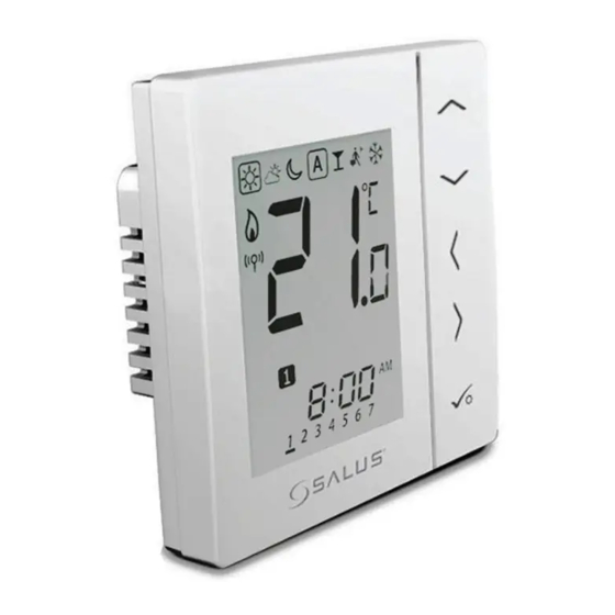
Installation – VS20WRF
Mount the back case of the thermostat on the wall. After that please insert the batteries and add
the front case. Make sure to use 4AAA Alkaline batteries.
Installation – Terminal Connections VS10WRF
Understanding your
1
terminal connections
Rear of unit
2
2
1
Installation – Receiver RX10RF (optional)
Note: Please install the RX10RF Receiver for your radiator system. This will ensure the
communication between the thermostat and the boiler, giving you the possibility to
switch the boiler on and off. The RX10RF receiver is optional and needs to be purchased
separately.
*Configured as RX1(boiler receiver)
Installation – First Power Up
The following screens show examples only
MCU software
* Please note that 88.8 and 8.8 are
version will
a reference to the software version.
be shown
Please make sure that your Universal Gateway is installed. You can use it with both internet
and non internet connection. The LED will be blue when connected to the internet and red
when it's not connected.
With Internet
Without Internet
RX10RF (optional
boiler switch)
If you are installing an underfloor system without an Internet connection, you can use the
coordinator from the KL08RF instead of the Universal Gateway.
Installation – Power Up your devices
Please follow the installation procedure for all equipment. After installation, your devices should
look like this:
Pairing for radiator system with Internet connection
Power Terminals
230 VAC
Used for supplying power
1
to the unit. 230V supply
can be sourced from
the wiring centre or any
convenient source.
Sensor Terminals
4
Can be used for external
AIR, Floor sensor when
configured as thermostat.
Can also be used for
Cylinder thermostat when
configured for HW.
6
8
*Configured as RX1
(stand alone receiver)
Wait until the LED is
solid red. Press the Open/
Close button once. When
ZIGBEE software
the initialization process is
version will
complete, the LED
be shown
will go off.
Press and hold the
for 10 seconds until the TRV
starts flashing red
10 sec
10
12
14
15
Please follow the on screen instruction in order to complete the pairing process.
Associate the TRV(s) to the thermostat(s) (mandatory)
16
1. During the first time installation, by easily following the App instructions
2
3
5
Tap Scan for equipment when
2. If you need to associate a TRV with a thermostat after the initial installation. This option can be
you want to start adding
used if you miss option 1, loss of TRV association or adding an additional TRV
equipment to the App. The
gateway will start flashing red.
7
9
Note: The TRV LED will flash orange until the association process is complete. Once this action has
finished the LED will go off.
Pairing for underfloor with Internet connection
1
4
6
.
8
11
10
13
On step 11 please select your zone number by using the UP or DOWN arrows.
12
When pairing the thermostats with the Wiring Center you can assign a group to a
programmable thermostat. This will allow control of up to 7 group thermostats. There
can be maximum 2 groups per Wiring Center.
13
Please follow the on screen instruction in order to complete the pairing process.
Follow the steps
described on the App
in order to complete
the association process
Tap on the
button
and select the TRV(s)
that you want to
associate to this
thermostat.
2
3
5
Tap Scan for equipment when
you want to start adding
equipment to the App. The
gateway will start flashing red.
7
9
11
Advertisement

Related Manuals for Salus VS20WRF


Summary of Contents for Salus VS20WRF
- Page 1 SALUS Smart Home system. Other Zigbee devices include wiring centre, system receiver & TRV. You can use your system with the SALUS Smart Home App. 10 sec Available on Google Play and App Store.
- Page 2 Setting the time (for systems without internet only) Pairing for radiator system without Internet connection Pairing for underfloor system without Internet connection 5 sec 5 sec Tap the Identify button. Your device will start flashing 3 Sec 5 sec Wait until the LED is solid red. Press the Open/Close button once.