
Related Manuals for AudioCodes Mediant 2600 SBC


Summary of Contents for AudioCodes Mediant 2600 SBC
- Page 1 Hardware Installation Manual AudioCodes Session Border Controller Series Mediant 2600 SBC...
- Page 2 Please contact your local recycling authority for disposal of this product. Customer Support Customer technical support and services are provided by AudioCodes or by an authorized AudioCodes Service Partner. For more information on how to buy technical support for AudioCodes products and for contact information, please visit our website at https://www.audiocodes.com/services-support/maintenance-and-support.
- Page 3 Notice Mediant 2600 SBC | Hardware Installation Manual Installation of this device must be in a weather protected location of maximum ambient temperature of 40°C. Avertissement: L’installation de cet appareil doit avoir lieu dans un local protégé des intempéries de température ambiante maximale de 40°C.
- Page 4 Notice Mediant 2600 SBC | Hardware Installation Manual Document Revision Record LTRT Description 41576 Initial versions. 41577 AC power cable warning (Japanese). 41578 Logo updated. 41579 19-inch rack mounting brackets updated. 42120 Fan tray and Power Supply modules replacement updated.
-
Page 5: Table Of Contents
Content Mediant 2600 SBC | Hardware Installation Manual Table of Contents Introduction Unpacking the Device Physical Description Physical Dimensions Front Panel Description Fan Tray Module Power Supply Modules Power LED Description E-SBC Module Ports Description LEDs Description Media Processing Module... -
Page 6: Introduction
CHAPTER 1 Introduction Mediant 2600 SBC | Hardware Installation Manual Introduction This document provides a hardware description of the Mediant 2600 (hereafter referred to as device) and step-by-step procedures for cabling the device. For configuring the device, refer to the device's User’s Manual. -
Page 7: Unpacking The Device
Two front-mounting brackets (with 6 screws) for 19-inch rack installation. ● Four anti-slide bumpers for desktop installation. ● Two-meter serial interface cable adaptor. Check, retain and process any documents. If there are any damaged or missing items, notify your AudioCodes sales representative. - 2 -... -
Page 8: Physical Description
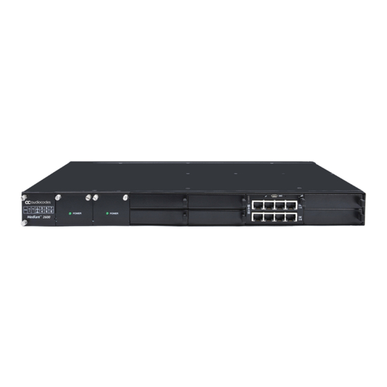
CHAPTER 3 Physical Description Mediant 2600 SBC | Hardware Installation Manual Physical Description This chapter provides a physical description of the device. Physical Dimensions The device's physical dimensions are listed in the following table. Table 3-1: Physical Dimensions Item Description Enclosure... -
Page 9: Fan Tray Module
CHAPTER 3 Physical Description Mediant 2600 SBC | Hardware Installation Manual Item # Component Description The following figure shows the location of the Fan Tray module, Power Supply modules, and chassis slot numbers: Power Supply module No. 2. For more information, see Power Supply Modules. -
Page 10: Power Supply Modules
CHAPTER 3 Physical Description Mediant 2600 SBC | Hardware Installation Manual Power Supply Modules The chassis houses up to two (hot-swappable|) Power Supply modules for providing power load sharing and AC power redundancy in case of failure of one of the Power Supply modules. Each module provides an AC power inlet on the rear panel of the chassis for connection to an electrical power outlet. -
Page 11: Leds Description
CHAPTER 3 Physical Description Mediant 2600 SBC | Hardware Installation Manual Figure 3-2: E-SBC Module Ports Table 3-4: E-SBC Module Ports Description Item # Label Description Reset pinhole button: To reset the device: Press and hold the button for up to 5 seconds ■... - Page 12 CHAPTER 3 Physical Description Mediant 2600 SBC | Hardware Installation Manual Figure 3-3: E-SBC Module LEDs Table 3-5: E-SBC Module LEDs Description Item # Color State Description Green Module in service Module out of service During booting up state Booting up phase / fault detected in...
-
Page 13: Media Processing Module
CHAPTER 3 Physical Description Mediant 2600 SBC | Hardware Installation Manual Item # Color State Description Left LED on Green Ethernet link established. Ethernet Flashing Data is being received or transmitted Ports (activity) on the Ethernet port. No Ethernet link. Right LED on... -
Page 14: Rear Panel Description
CHAPTER 3 Physical Description Mediant 2600 SBC | Hardware Installation Manual Figure 3-4: MPM LEDs Table 3-6: MPM LEDs Description Item # Color State Description Green Module in service Module out of service Booting up phase Green Normal operation Green Application running... - Page 15 CHAPTER 3 Physical Description Mediant 2600 SBC | Hardware Installation Manual Figure 3-5: Rear Panel Table 3-7: Rear-Panel Description Item # Label Description AC power supply inlet (100-240V~2.5A, 50-60 Hz) for Power Supply module No. 1. AC power supply inlet (100-240V~2.5A, 50-60 Hz) for Power Supply module No.
-
Page 16: Mounting The Device
CHAPTER 4 Mounting the Device Mediant 2600 SBC | Hardware Installation Manual Mounting the Device The device can be mounted in one of the following ways: ■ Placed on a desktop (see Desktop Mounting) Installed in a standard 19-inch rack (see Rack Mounting) ■... -
Page 17: Rack Mounting
CHAPTER 4 Mounting the Device Mediant 2600 SBC | Hardware Installation Manual Flip the device over again so that it rests on its underside with the rubber feet in contact with the surface. Rack Mounting The device is designed to fit into a 19-inch industrial rack of 1 rack-unit height (1U). You can mount it in the rack using any one of the following mounting options: ■... -
Page 18: Mounting In A 19-Inch Rack Using Front And Rear Brackets
CHAPTER 4 Mounting the Device Mediant 2600 SBC | Hardware Installation Manual Place the device on the pre-installed shelf in the rack. Position the chassis so that the front-mounting brackets are flush against the front rack posts and that the holes of the brackets align with the holes on the posts. - Page 19 CHAPTER 4 Mounting the Device Mediant 2600 SBC | Hardware Installation Manual ■ Rear-mounting brackets suited for rack depths of approximately 80 cm (CPN for ordering is FRU/M26-83/REARRMK80): Adjustable rear-mounting bracket whose length can be adjusted from 77 to 83 cm (30.3 to 32.6 in.) to suit the distance between the chassis and the rear post.
- Page 20 CHAPTER 4 Mounting the Device Mediant 2600 SBC | Hardware Installation Manual Figure 4-2: Rear-Mounting Brackets Attached to Rear-Rack Posts (60 cm) Figure 4-3: Rear-Mounting Brackets Attached to Rear-Rack Posts (> 70 cm) Attach the rear-mounting flanges to the rear sides of the chassis, using three screws (supplied) per flange.
- Page 21 CHAPTER 4 Mounting the Device Mediant 2600 SBC | Hardware Installation Manual Figure 4-4: Attaching Rear-Mounting Flange to Chassis' Rear-Side Mounting Holes (60 cm) Figure 4-5: Attaching Rear-Mounting Flange to Chassis' Rear-Side Mounting Holes (> 70 cm) With two people, lift the chassis into the rack from the front of the rack.
- Page 22 CHAPTER 4 Mounting the Device Mediant 2600 SBC | Hardware Installation Manual Figure 4-6: Sliding Rear-Mounting Flanges into the Rear-Mounting Brackets (60 cm) Figure 4-7: Sliding Rear-Mounting Flanges into the Rear-Mounting Brackets (> 70 cm) Hold the chassis in position while the second person secures the rear-mounting flanges to the rear-mounting brackets.
- Page 23 CHAPTER 4 Mounting the Device Mediant 2600 SBC | Hardware Installation Manual Figure 4-9: Fastening Rear-Mounting Flange to Rear-Mounting Bracket (> 70 cm) Hold the chassis for support while the second person positions the chassis so that the front- mounting brackets are flush against the front-rack posts and that the holes of the front- mounting brackets align with the holes on the front-rack posts.
- Page 24 CHAPTER 4 Mounting the Device Mediant 2600 SBC | Hardware Installation Manual Figure 4-11: Front-Mounting Brackets Flush and Aligned with Front-Rack Posts (> 70 cm) Hold the chassis in position while the second person secures the two front-mounting brackets to the front posts, by finger-tightening 19-inch rack bolts (not supplied) to the rack posts.
-
Page 25: Cabling The Device
CHAPTER 5 Cabling the Device Mediant 2600 SBC | Hardware Installation Manual Cabling the Device This section describes how to cable the device: ■ Grounding the device – see Grounding the Device Connecting to the LAN – see Connecting the Ethernet Ports ■... -
Page 26: Rj-45 Lan Connector Pinouts
CHAPTER 5 Cabling the Device Mediant 2600 SBC | Hardware Installation Manual RJ-45 LAN Connector Pinouts The RJ-45 connectors with the following pinouts are used for the LAN interfaces: Table 5-1: RJ-45 Connector Pinouts Name Description BI_DA+ Bi-directional pair A+ BI_DA-... -
Page 27: Deployment Of Two Devices For High Availability
CHAPTER 5 Cabling the Device Mediant 2600 SBC | Hardware Installation Manual By default, the Ethernet ports are grouped into pairs, as shown below. However, you can change this port assignment, including assigning only a single port to an Ethernet Group. For more information, refer to the User's Manual. -
Page 28: Connecting The Serial Interface To A Computer
CHAPTER 5 Cabling the Device Mediant 2600 SBC | Hardware Installation Manual Figure 5-5: Cabling for High Availability (Example) In High Availability, the two devices interconnect through their Maintenance interfaces, using the same Ethernet Port Group. For possible connections (including Tx / Rx settings) between the HA devices, refer to the User's Manual. -
Page 29: Connecting To Power
CHAPTER 5 Cabling the Device Mediant 2600 SBC | Hardware Installation Manual Figure 5-7: Connecting the Serial Interface On the other end of the cable, connect the DB-9 connector labeled "P1" (red) to the RS-232 communication port on your computer. ●... - Page 30 CHAPTER 5 Cabling the Device Mediant 2600 SBC | Hardware Installation Manual ご注 意 本 製 品 に添 付 の電 源 ケーブルは、 Mediant 2600 E-SBC に専 用 設 計 さ れているため、 汎 用 性があり ません. 本 電 源 ケーブルを他の機 器に使 用 さ れないよう 、 ご注 意 く ださ い.
-
Page 31: Hardware Maintenance
CHAPTER 6 Hardware Maintenance Mediant 2600 SBC | Hardware Installation Manual Hardware Maintenance The device is designed as a modular chassis and allows you to order any module as a Field Replacement Unit (FRU). This section describes the procedures for installing or replacing modules. -
Page 32: Replacing The E-Sbc Module
CHAPTER 6 Hardware Maintenance Mediant 2600 SBC | Hardware Installation Manual Figure 6-1: Connecting ESD Wrist Strap to Chassis ESD Lug Replacing the E-SBC Module The AMC-based E-SBC module is hot-swappable and can be replaced without powering down the device and disrupting other non-related services running on the device. -
Page 33: Installing The Mpm
CHAPTER 6 Hardware Maintenance Mediant 2600 SBC | Hardware Installation Manual Figure 6-3: Module Handle Pushed In (Top View) Connect all external interfacing cables to the module, as required. Installing the MPM The procedure below describes how to install the MPM into the chassis. -
Page 34: Replacing The Fan Tray Module
CHAPTER 6 Hardware Maintenance Mediant 2600 SBC | Hardware Installation Manual If you purchased this device in an initial release where the E-SBC module is housed in Slots 3-4, you must relocate this module to Slots 5-6 instead, as shown below: Follow the instructions in Section Replacing the E- SBC Module for replacing this module. -
Page 35: Replacing The Power Supply Module
CHAPTER 6 Hardware Maintenance Mediant 2600 SBC | Hardware Installation Manual Using a flathead screwdriver, tighten the two module's mounting pins. Fasten the two screws on the top right-hand corner and the bottom right-hand corner of the front panel of the Fan Tray module. - Page 36 CHAPTER 6 Hardware Maintenance Mediant 2600 SBC | Hardware Installation Manual This page is intentionally left blank. - 31 -...
- Page 37 ©2022 AudioCodes Ltd. All rights reserved. AudioCodes, AC, HD VoIP, HD VoIP Sounds Better, IPmedia, Mediant, MediaPack, What’s Inside Matters, OSN, SmartTAP, User Management Pack, VMAS, VoIPer- fect, VoIPerfectHD, Your Gateway To VoIP, 3GX, VocaNom, AudioCodes One Voice, AudioCodes Meeting Insights, AudioCodes Room Experience and CloudBond are trademarks or registered trademarks of Audi- oCodes Limited.