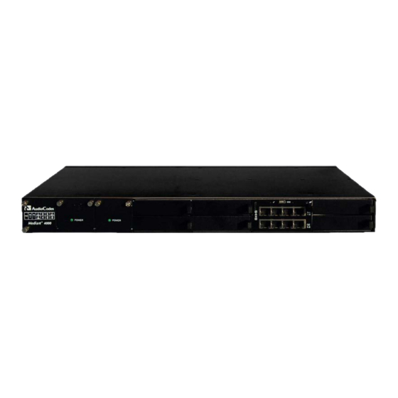
AudioCodes Mediant 4000 E-SBC Hardware Installation Manual
Enterprise session border controller, high-availability system
Hide thumbs
Also See for Mediant 4000 E-SBC:
- Configuration note (46 pages) ,
- Configuration note (20 pages)

Related Manuals for AudioCodes Mediant 4000 E-SBC


Summary of Contents for AudioCodes Mediant 4000 E-SBC
- Page 1 Mediant™ 4000 E-SBC Enterprise Session Border Controller High-Availability System Hardware Installation Manual Version 6.6 September 2013 Document # LTRT-41503...
-
Page 3: Table Of Contents
Hardware Installation Manual Contents Table of Contents Introduction ......................7 Unpacking the Device ..................9 Physical Description ..................11 Physical Dimensions ....................11 Front Panel Description ..................11 3.2.1 Fan Tray Module ...................... 12 3.2.2 Power Supply Modules .................... 12 3.2.2.1 Power LED Description ................13 3.2.3... - Page 4 Mediant 4000 E-SBC List of Figures Figure 3-1: Front Panel .......................... 11 Figure 3-2: E-SBC Module Ports ......................13 Figure 3-3: E-SBC Module LEDs ......................14 Figure 3-4: MPM LEDs .......................... 16 Figure 3-5: Rear Panel .......................... 17 Figure 4-1: Rubber Feet Locations ......................19 Figure 4-2: Rear Mounting Brackets Attached to Rear Rack Posts ............
- Page 5 This document is subject to change without notice. Date Published: September-01-2013 Trademarks AudioCodes, AC, AudioCoded, Ardito, CTI2, CTI², CTI Squared, HD VoIP, HD VoIP Sounds Better, InTouch, IPmedia, Mediant, MediaPack, NetCoder, Netrake, Nuera, Open Solutions Network, OSN, Stretto, TrunkPack, VMAS, VoicePacketizer, VoIPerfect, VoIPerfectHD, What’s Inside Matters, Your Gateway To VoIP and 3GX are trademarks or...
- Page 6 Documentation Feedback AudioCodes continually strives to produce high quality documentation. If you have any comments (suggestions or errors) regarding this document, please fill out the Documentation Feedback form on our Web site at http://www.audiocodes.com/downloads.
-
Page 7: Introduction
Hardware Installation Manual 1. Introduction Introduction This document provides a hardware description of the Mediant 4000 (hereafter referred to as device) and step-by-step procedures for cabling the device. Note: For information on configuring the device, refer to the device's User’s Manual. Version 6.6 September 2013... - Page 8 Mediant 4000 E-SBC Reader’s Notes Hardware Installation Manual Document #: LTRT-41503...
-
Page 9: Unpacking The Device
Adjustable Rear-Rack Mounting Bracket Kit for mounting the chassis in a 19-inch rack • Two-meter serial interface cable adaptor. Check, retain and process any documents. If there are any damaged or missing items, notify your AudioCodes sales representative. Version 6.6 September 2013... - Page 10 Mediant 4000 E-SBC Reader's Notes Hardware Installation Manual Document #: LTRT-41503...
-
Page 11: Physical Description
Hardware Installation Manual 3. Physical Description Physical Description This section provides a physical description of the device. Physical Dimensions The device's physical dimensions are listed in the table below. Table 3-1: Physical Dimensions Item Description Enclosure 4/8-slot, 1U chassis Dimensions (H x W x D) 1U x 19”... -
Page 12: Fan Tray Module
Mediant 4000 E-SBC Table 3-2: Front-Panel Description Item # Component Description Fan Tray module with a schematic displayed on its front panel showing the chassis' slot numbers. For more information on this module, see Section 3.2.1 on page 12. The figure below shows the location of the Fan Tray module, Power Supply modules, and chassis slot numbers: Power Supply module No. -
Page 13: Power Led Description
Hardware Installation Manual 3. Physical Description 3.2.2.1 Power LED Description Each Power Supply module provides a POWER LED on its front panel which indicates the status of the power supply, as described in the table below. Table 3-3: Power Supply Module LED Description Color State Description... -
Page 14: Leds Description
Mediant 4000 E-SBC Table 3-4: E-SBC Module Ports Description Item # Label Description Reset pinhole button: To reset the device, press the button for at least 1 second but no longer than 10 seconds. To reset the device to factory defaults, press the button for at least 12 seconds but no longer than 25 seconds. -
Page 15: Table 3-5: E-Sbc Module Leds Description
Hardware Installation Manual 3. Physical Description Table 3-5: E-SBC Module LEDs Description Item # Color State Description Green Module in service Module out of service During booting up state Booting up phase / fault detected in module Green Normal operation During booting up state Green Application running in Standalone state... -
Page 16: Media Processing Module
Mediant 4000 E-SBC 3.2.4 Media Processing Module The Media Processing module (MPM) is an optional, customer-ordered module that provides additional digital signaling resources (DSP) required for transcoding call sessions. The addition of this module increases the maximum number of sessions that can undergo transcoding. -
Page 17: Rear Panel Description
Hardware Installation Manual 3. Physical Description Rear Panel Description The chassis rear panel is displayed in the figure below and described in the subsequent table. Figure 3-5: Rear Panel Table 3-7: Rear-Panel Description Item # Label Description AC power supply inlet (100-240V~2.5A, 50-60 Hz) for Power Supply module No. - Page 18 Mediant 4000 E-SBC Reader's Notes Hardware Installation Manual Document #: LTRT-41503...
-
Page 19: Mounting The Device
Hardware Installation Manual 4. Mounting the Device Mounting the Device The device can be mounted in one of the following ways: Placed on a desktop - see Section 'Desktop Mounting' on page Installed in a standard, 19-inch rack - see Section ‘Rack Mounting' on page Warning: The side panels of the chassis where the air vents are located must remain unobstructed to ensure adequate airflow and prevent overheating inside... -
Page 20: 19-Inch Rack Mounting
Mediant 4000 E-SBC 19-Inch Rack Mounting The device is designed to fit into a 19-inch industrial rack of 1 rack-unit height (1U). You can mount it in the rack using any one of the following mounting options: (Recommended) Mounting the chassis on a pre-installed shelf in a 19-inch rack – see Section 4.2.1... -
Page 21: Mounting In A 19-Inch Rack Using A Pre-Installed Rack Shelf
Hardware Installation Manual 4. Mounting the Device 4.2.1 Mounting in a 19-inch Rack using a Pre-Installed Rack Shelf The device can be placed on a pre-installed shelf in a 19-inch rack, as described below. This is the recommended method for mounting the device. ... -
Page 22: Figure 4-2: Rear Mounting Brackets Attached To Rear Rack Posts
Mediant 4000 E-SBC Attach the two rear mounting brackets to the two rear rack posts, using two screws (not supplied) for each bracket. Make sure that you attach the brackets at the same height level in the rack. See the figure below for correct orientation of the brackets when attaching them to the posts. -
Page 23: Figure 4-4: Sliding The Rear Mounting Flanges Into The Rear Mounting Brackets
Hardware Installation Manual 4. Mounting the Device Slide the two rear mounting bracket flanges into the slide rails of the rear mounting brackets that you previously attached to the rear posts. Figure 4-4: Sliding the Rear Mounting Flanges into the Rear Mounting Brackets Hold the chassis in position while the second person secures the rear mounting flanges to the rear mounting brackets. -
Page 24: Figure 4-6: Front Mounting Brackets Flush And Aligned With Front Rack Posts
Mediant 4000 E-SBC Hold the chassis for support while the second person positions the chassis so that the front mounting brackets are flush against the front rack posts and that the holes of the brackets align with the holes on the posts. -
Page 25: Cabling The Device
Hardware Installation Manual 5. Cabling the Device Cabling the Device This section describes how to cable the device: Grounding the device – see Section on page Connecting to the LAN – see Section on page Connecting to a computer for serial communication – see Section on page ... -
Page 26: Connecting The Ethernet Ports
Mediant 4000 E-SBC Connecting the Ethernet Ports This section describes the cabling of the LAN interfaces. 5.2.1 RJ-45 LAN Connector Pinouts The RJ-45 connectors with the following pinouts are used for the LAN interfaces: Table 5-1: RJ-45 Connector Pinouts Name... -
Page 27: Deployment Of A Standalone Device
Hardware Installation Manual 5. Cabling the Device 5.2.2 Deployment of a Standalone Device The Ethernet ports on the E-SBC module operate in pairs to provide Ethernet port 1+1 redundancy. In each pair, one port serves as the active Ethernet port while the other as standby. -
Page 28: Deployment Of Two Devices For High Availability
Mediant 4000 E-SBC 5.2.3 Deployment of Two Devices for High Availability The device supports 1+1 high availability, whereby two devices are deployed and connected to the same broadcast domain/s. In such a setup, the same Ethernet port-pair redundancy setup is done for each device. For example, if port-pair 5 and 6 are used for Device "A", then Device "B"... -
Page 29: Connecting The Serial Interface To A Computer
Hardware Installation Manual 5. Cabling the Device Connecting the Serial Interface to a Computer The RS-232 interface port is used to access the command line interface (CLI) for serial communication. The cable adapter shown below is provided for this purpose: Figure 5-6: Serial Interface Cable Adapter and Connector Pinouts ... -
Page 30: Connecting To Power
Mediant 4000 E-SBC Connecting to Power The procedure below describes how to connect the device to the power supply. Warnings: • The device must be connected (by service personnel) to a socket-outlet with a protective earthing connection. • Use only the AC power cord supplied with the device. -
Page 31: Hardware Maintenance
Hardware Installation Manual 6. Hardware Maintenance Hardware Maintenance The device is designed as a modular chassis and allows you to order any module as a Field Replacement Unit (FRU). This section describes the procedures for installing or replacing modules. Warning: Maintenance service of this device must be made only by qualified service personnel in restricted access locations and connected to an earthed power socket. -
Page 32: Removing Kapton Tape Before Installing Modules
Mediant 4000 E-SBC 6.1.3 Removing Kapton Tape before Installing Modules Some modules are shipped with Kapton tape covering their gold fingers (edge connector). The Kapton tape is used to protect the module's BUS line. Before installing a new module, this tape must be removed. If not removed, the module may not be functional, chassis operation may be compromised and irreversible damage may be caused to the chassis. -
Page 33: Installing The Mpm
Hardware Installation Manual 6. Hardware Maintenance Installing the MPM The procedure below describes how to install the MPM into the chassis. Warning: Power down the device before installing the MPM. To install the MPM: Remove the new MPM from its ESD shielding packet in which it was shipped. If the gold fingers of the module have Kapton tape covering, remove the tape as described in Section 6.1.3... -
Page 34: Replacing The Fan Tray And Power Supply Modules
Mediant 4000 E-SBC Replacing the Fan Tray and Power Supply Modules This section describes how to replace the Fan Tray and Power Supply modules. Warnings: • Do not operate the device without the Fan Tray module! Before replacing the Fan Tray module, ensure that you have the replacement Fan Tray module on hand. - Page 35 Hardware Installation Manual 6. Hardware Maintenance Reader's Notes Version 6.6 September 2013...
- Page 36 Hardware Installation Manual www.audiocodes.com...