
Related Manuals for Extron electronics IP Link Pro xi IPL EXP PDU4H


Summary of Contents for Extron electronics IP Link Pro xi IPL EXP PDU4H
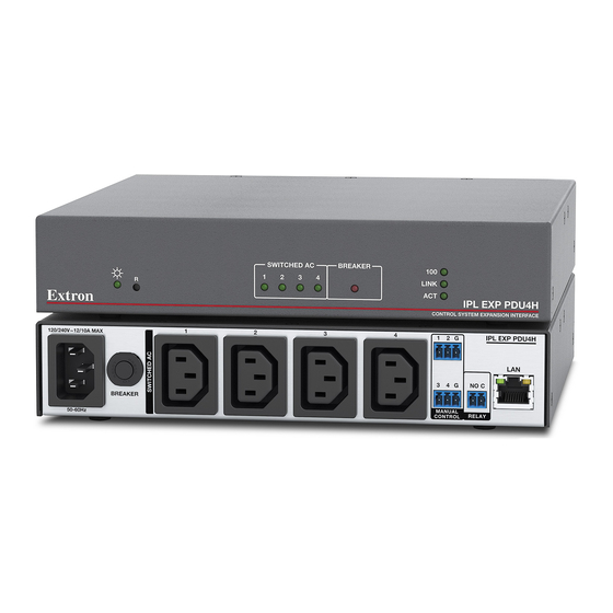
- Page 1 User Guide IP Link Pro xi Products ® IPL EXP PDU4H Control System Power Expansion Interface 68-3495-01 Rev. A 02 22...
- Page 2 Safety Instructions...
- Page 3 Copyright © 2022 Extron. All rights reserved. www.extron.com Trademarks All trademarks mentioned in this guide are the properties of their respective owners. The following registered trademarks (®), registered service marks ( ), and trademarks (™) are the property of RGB Systems, Inc. or Extron (see the current list of trademarks on the Terms of Use page at www.extron.com):...
- Page 4 FCC Class B Notice NOTE: This device complies with part 15 of the FCC rules. Operation is subject to the following two conditions: (1) This device may not cause harmful interference, and (2) This device must accept any interference received, including interference that may cause undesired operation.
- Page 5 Conventions Used in this Guide Notifications The following notifications are used in this guide: CAUTION: Risk of minor personal injury. ATTENTION : Risque de blessure mineure. ATTENTION: • Risk of property damage. • Risque de dommages matériels. NOTE: A note draws attention to important information. TIP: A tip provides a suggestion to make working with the application easier.
-
Page 7: Table Of Contents
Contents Introduction Modes of Operation, ........... 1 SIS Configuration and Control ....22 Before You Begin ..........1 Modes of Operation .......... 22 What This Guide Covers ......... 1 Manual Control Mode ........22 Conventions Used in This Guide ..... 1 SIS‑Over‑SSH Mode........ - Page 8 Reference Information Firmware Updates ....... 42 ........46 Network Port Requirements and Licensed Determining the Firmware Version ..... 46 Third‑Party Software ........42 Using Toolbelt Software ........ 46 File Types: a Key to Extron‑specific Using a Browser ........... 46 File Names ............42 Updating the Firmware ........
-
Page 9: Introduction
Introduction This section covers the following basic information you should know about this guide and the product before installation: • Before You Begin • About Global Configurator • About the IPL EXP PDU4H • About Global Scripter • Application Diagram • PC System Requirements Operation Modes •... -
Page 10: Important Information You Need Before Installation
• The GlobalViewer Enterprise application is sometimes referred to as “GVE.” Unless otherwise noted, in images of software or web pages, circled numbers • correspond to the like‑numbered procedural steps. Important Information You Need Before Installation The order and types of setup tasks for the IPL EXP PDU4H expansion interface, and for the IPCP Pro xi Series control processors and TouchLink Pro touchpanels and NBP setup button panels they work with, are important. -
Page 11: Features
The system supports multiple TouchLink Pro touchpanels and NBP button panels over a standard Ethernet network. The touchpanels and button panels provide a convenient interface for controlling the IPCP, which, in turn, controls the other system components. Another option is to use a third‑party device such as a touchpanel or tablet in conjunction with Extron LinkLicense. -
Page 12: Application Diagram
System asset management — The configured system and expansion interface allow • you to control, monitor, and schedule various functions of devices in the system. Additional security features — Each expansion interface and control processor can • use the included Secure Sockets Layer (SSL) certificate or a user‑supplied, customized security certificate (see Secure Sockets Layer (SSL) Certificates on page 43). -
Page 13: Operation Modes
Operation Modes The IPL EXP PDU4H has three modes of operation: Manual control (using the Manual Control contact closure ports) • • Enabled at all times • Takes precedence over the other two modes • Simple Instruction Set (SIS-over-SSH) control • Enabled by default Allows non‑Extron devices to use Ethernet communication to command the •... -
Page 14: Pc System Requirements
PC System Requirements To find the minimum hardware and software requirements for the PC you use to configure the control system: Download • Visit the page (www.extron.com/download/index.aspx) on the Extron website and navigate to the web page for the specific software package (such as Global Configurator and GUI Designer). -
Page 15: Hardware Features And Installation
Hardware Features and Installation This section covers the following material: • Setup Checklist — A checklist of tasks to guide you through installation • Network Communication Setup — A flowchart guide to network settings configuration • Features — Locations and some descriptions of items on the front panel Mounting •... -
Page 16: Mount And Cable All Devices
… Obtain network information for the unit from the network administrator. You also need the following details for each Extron Pro series Ethernet‑enabled device: … … DHCP setting (on or off) Subnet mask … … Device (IPL EXP, TLP Pro, IPCP Pro Qxi or xi, NBP) LAN Gateway IP address IP address …... -
Page 17: Configure Or Program The Control Processor, Expansion Interfaces, Touchpanels, And Network Button Panels
Configure or Program the Control Processor, Expansion Interfaces, Touchpanels, and Network Button Panels NOTE: Building and uploading a GC or GS project changes the state of the ports to factory default, or to the configured or programmed values, depending on the actions defined in the project. -
Page 18: Test And Troubleshoot
… If not using GC Professional or GC Plus, use Global Scripter to program the control system as desired. … Program ports on the control processor: Program each serial, IR/serial, or Ethernet port as needed. … … Program relay behavior, digital I/O, flex I/O, and AC output settings as needed. …... -
Page 19: Features
Features This section shows panel features and their locations. Most of the features and LED indications are described and shown in the Cabling, Addressing, Features, and Connections section starting on page 14 paired with the descriptions of the corresponding ports. Front Panel Features SWITCHED AC BREAKER LINK... -
Page 20: Mounting
Mounting Mounting Options Optional 1U rack shelves and a variety of rack mounting bracket kits and furniture mounting kits are available for use with the IPL EXP PDU4H. The unit can be mounted to the following items: • tabletop • equipment rack rails •... -
Page 21: Rack Mounting
Consignes UL pour le montage en rack Les consignes UL (« Underwriters Laboratories ») suivantes concernent l’installation en rack d’un boîtier IPL EXP PDU4H: CAUTION: • Température ambiante élevée — En cas d’installation de l’équipement dans un rack fermé ou composé de plusieurs unités, la température du rack peut être supérieure à... -
Page 22: Cabling, Addressing, Features, And Connections
• Always use the power cord provided with the unit. • Veillez à toujours utiliser le câble d’alimentation fourni avec l’unité. • Should you need to use a different power cord, consult Extron Electronics prior to using the cord. • Si vous devez utiliser un autre câble d’alimentation, contactez Extron Electronics avant d’utiliser ce câble. - Page 23 Power input After connecting cables to the other ports, connect a cable from the 120 VAC or 240 VAC, 50‑60 Hz mains power source to this IEC plug. Rear Panel Front Panel 100/240V ~ 12/10A MAX Power Input • Connect to •...
- Page 24 Circuit Breaker Switched AC Power Output (power output overcurrent protection) Connect AC powered products to these four ports Rear Panel using a standard IEC power cord, or use an Extron IEC-to-Edison cable kit if your devices require NEMA 5-15R receptacles. /240V ~ 12/10A •...
-
Page 25: Unidirectional Control Connections
Unidirectional Control Connections Manual Control (contact closure) ports These four ports are dedicated contact input ports, used exclusively to control the corresponding power output ports. When the circuit between a signal pin and a ground pin is closed, each port turns on the corresponding AC power output port. •... -
Page 26: Bidirectional Control And Communication Connection
Relay port Connect this relay output port to a notification device to create visual or audio alerts for triggering conditions such as power output shutdown (once the port conditions, events, and notifications are configured). The relay contacts may Relay is be used to control any normally open. - Page 27 For details of communication protocols, ports, and services used, see the Pro Series Control Product Network Ports and Licenses Guide at www.extron.com. LED Indication: • Activity LED (connector and front panel) — This yellow LED blinks to indicate network activity. Link LED (connector and front panel) —...
-
Page 28: Resetting The Unit
Resetting the Unit There are four reset modes that are available by pressing the Reset Reset button on the front panel. The button is recessed, so use a pointed stylus, ballpoint pen, or Extron Tweeker to access it. See the reset modes table below and on the next pages for a summary of the modes. - Page 29 IPL EXP PDU4H Expansion Interface Reset Mode Summary Use This Activation Result Mode to... Reset IP To reset all IP settings: Reset All IP Settings mode: settings and Reset Press and hold the button until the Reset or Power Turns DHCP off. •...
-
Page 30: Modes Of Operation, Sis Configuration And Control
Modes of Operation, SIS Configuration and Control This section of the guide is divided into the following topics: Modes of Operation • • SIS Configuration and Control Modes of Operation The IPL EXP PDU4H has three control modes: • Manual control mode Simple Instruction Set (SIS)‑over‑SSH mode •... -
Page 31: Secure Platform Device Mode
When SIS‑over‑SSH mode is disabled, all SIS‑over‑SSH requests (aside from the query about the current mode of operation) are unsuccessful, and the unit returns error code 37: Invalid command while in SPD mode. The SIS command to query the operation mode of the IPL EXP PDU4H is a query only, not a command to set the mode. -
Page 32: Host Control Port
Host Control Port The factory default network settings for the power expansion interface are: 192.168.254.250 • IP address 255.255.255.0 Subnet mask • 0.0.0.0 • Gateway address 127.0.0.1 DNS address • Establishing a Connection Establish a network connection to the IPL EXP PDU4H as follows: Download the SSH client application. -
Page 33: Error Responses
Error Responses When the unit receives a valid SIS command, it executes the command and sends a response to the host device. If the IPL EXP PDU4H is unable to execute the command because the command is invalid or it contains invalid parameters, the unit returns an error response to the host. -
Page 34: Command Symbol Definitions
Command Symbol Definitions Carriage return/line feed (hex 0D 0A) • space character } or Carriage return (no line feed ) (for URL‑encoded commands, use the pipe , hex 0D character, , instead) Escape key Pipe (vertical bar) character Asterisk character (which is a command character, not a variable) = Power output number = all outputs = outputs 1‑4... - Page 35 = Reading password Instead of the actual password, the unit responds with four asterisks (****) if a password exists, and it responds with an empty field (nothing) if no password exists. = Default unit name Default unit name is a combination of the modelname and last three pairs of the MAC address (such as IPL-EXP-PDU4H-00-02-3D X7&...
-
Page 36: Command And Response Table For Sis Commands
Command and Response Table for SIS Commands SIS Command Response Additional description Command Function (Host to Unit) (Unit to Host) Manual Control port input state View the state of the input as selected by Manual Control port Verbose mode 2/3: X@ X%] Power receptacle control and current sensing Turn receptacle power on... - Page 37 SIS Command Response Additional description Command Function (Host to Unit) (Unit to Host) Power receptacle scheduling E X71* X71! X71@ SS } Set scheduling Sst X! X71* X71! X71@] E 1*2*5*1*600SS } Sst2*1*5*1*600 ] Example: For AC power port 2, Thursday turn the port on at 10:00AM (at 600 minutes).
- Page 38 SIS Command Response Additional description Command Function (Host to Unit) (Unit to Host) Unit information queries, continued X56& specific version information View firmware version (advanced) Verbose mode 2/3: Ver X56& specific version information View the firmware version x.xx Verbose mode 2/3: Ver 01*x.xx x.xx.xxxx ] View the full firmware version with...
- Page 39 SIS Command Response Additional description Command Function (Host to Unit) (Unit to Host) Ethernet data port timeout period X6(] Set the current Ethernet port Pti0* Set the number of seconds to wait connection timeout period without receiving data before the IP connection times out (the unit closes the Ethernet connection).
- Page 40 SIS Command Response Additional description Command Function (Host to Unit) (Unit to Host) IP setup commands, continued X1$ ] E X1$ Set IP address Ipi• 14. 24 X1$] View IP address X57& Set IP address/subnet/gateway CISG (IPv4) (preferred method) X57& X1$] Cisg•1* X57&...
- Page 41 SIS Command Response Additional description Command Function (Host to Unit) (Unit to Host) SIS-over-SSH, SSL, and SFTP port mapping Set SIS‑over‑SSH port map port number Set the SIS‑over‑SSH port to a number of }PMAP your choice. port number PmapB { Reset SIS‑over‑SSH port map B 22023 PMAP PmapB 22023...
- Page 42 SIS Command Response Additional description Command Function (Host to Unit) (Unit to Host) SNMP (Simple Network Management Protocol) X58! X58!] X58! Set SNMP unit contact SNMP SnmpC* Sets unit contact to Set SNMP unit contact to C•SNMP SnmpC*Not•Specified default View SNMP unit contact X58!] View the text of the unit contact.
- Page 43 SIS Command Response Additional description Command Function (Host to Unit) (Unit to Host) Resets Zpx ] Reset unit settings ZXXX Reset all settings (except IP settings) to factory default settings. Excludes IP settings such as IP address, subnet mask, unit name, gateway address, and passwords, and does not remove file system settings.
-
Page 44: Software-Based Configuration And Control
Software-Based Configuration and Control This section of the guide is divided into the following topics: Configuration and Control: An Overview • • Basic Setup Steps: a Guide to this Section and Other Resources Downloading the Software and Getting Started • •... -
Page 45: Basic Setup Steps: A Guide To This Section And Other Resources
Basic Setup Steps: a Guide to this Section and Other Resources NOTE: GC projects can be created offline and uploaded to the hardware at a later date. Follow the steps in Setup Checklist starting on page 7. The overall process for setting up a control processor using GC is as follows: Within Global Configurator Configure the IP settings... -
Page 46: Downloading The Software And Getting Started
Downloading the Software and Getting Started Download GC software updates, GS, and Toolbelt can be downloaded from the page on the Extron website (www.extron.com/download/index.aspx). When you locate the desired software, follow the on‑screen directions to download and install it. Locating Software and Firmware on the Extron Website There are three main ways to find software and firmware within www.extron.com: •... -
Page 47: Things To Do After Installing Gc And Before Starting A Project
Via links from search results Type the specific name of the software package (such as Global Configurator or Search GUI Designer) into the field in the upper right of the Extron web page and click magnifying glass icon. A search results page appears. Click on the name of the software package. -
Page 48: Troubleshooting
• The unit (host) name is any name (for example, Room730‑IPLEXPPDU4H or ConfRmSyst) that you want to use to label a specific EXP unit. The default is a combination of the product name and part of the hardware (MAC) address. This can be changed to your choice of alphanumeric characters and hyphens (‑). -
Page 49: Data Connections
Connect devices one at a time, allowing the IPL EXP to check current levels between each device. If connecting any device causes the circuit breaker to trip, disconnect that device and do not reconnect it. Reset the circuit breaker, then turn on the remaining connected devices. Normal operation should resume. -
Page 50: Reference Information
Reference Information This section of the guide includes the following reference items: • Network Port Requirements and Licensed Third-Party Software File Types: a Key to Extron-specific File Names • Secure Sockets Layer (SSL) Certificates • • IEEE 802.1X Certificates SNMP •... -
Page 51: Secure Sockets Layer (Ssl) Certificates
Secure Sockets Layer (SSL) Certificates Extron control processors and expansion interfaces ship with factory‑installed SSL certificates created by Extron. If you want or are required to use a different SSL certificate at your installation site, then you can use system utilities in the Toolbelt software to change the SSL certificate at any time. -
Page 52: Certificate File Requirements
The Extron implementation of 802.1X supports PEAP ‑ MSCHAPV2 and EAP ‑ TLS methods of authentication. This section of the guide details the requirements for any certificate file private key file (machine or CA) and the (for the machine certificate) to be used in the system. -
Page 53: Private Key File Requirements
Its file name consists of the following types of valid characters: • • Alphanumerical (A‑Z, a‑z, 0‑9) characters • Some special characters (colon [ : ], underscore [ _ ], and hyphen [ ‑ ]) • It has a file extension that is .key or .pem. •... -
Page 54: Firmware Updates
Firmware Updates If the need arises, you can replace the IPL EXP firmware. This section covers the following firmware‑related topics: • Determining the Firmware Version • Updating the Firmware Determining the Firmware Version There are several ways to check which firmware version the control processor is using: View the device information in Toolbelt. -
Page 55: Updating The Firmware
Updating the Firmware Firmware upgrade tools require the PC and the control processor to both be connected to an Ethernet network. The instructions for updating the IPL EXP firmware assume you have installed the appropriate software on your PC first. NOTES: •... - Page 56 Extron Warranty Extron warrants this product against defects in materials and workmanship for a period of three years from the date of purchase. In the event of malfunction during the warranty period attributable directly to faulty workmanship and/ or materials, Extron will, at its option, repair or replace said products or components, to whatever extent it shall deem necessary to restore said product to proper operating condition, provided that it is returned within the warranty period, with proof of purchase and description of malfunction to: USA, Canada, South America,...