
Related Manuals for Endress+Hauser Picomag IO-Link


Summary of Contents for Endress+Hauser Picomag IO-Link
- Page 1 Products Solutions Services BA01697D/06/EN/06.22-00 71552010 2022-06-01 Valid as of version 01.01.zz (Device firmware) Operating Instructions Picomag IO-Link Electromagnetic flowmeter...
- Page 2 • The manufacturer reserves the right to modify technical data without prior notice. Your Endress+Hauser Sales Center will supply you with current information and updates to these instructions. Endress+Hauser...
-
Page 3: Table Of Contents
Picomag IO-Link Table of contents Table of contents About this document ....5 Operation options ....20 Document function . - Page 4 Table of contents Picomag IO-Link Appendix ......47 14.1 Radio approvals ..... . . 47 14.1.1 Argentina .
-
Page 5: About This Document
Picomag IO-Link About this document About this document Document function These Operating Instructions contain all the information that is required in various phases of the life cycle of the device: from product identification, incoming acceptance and storage, to mounting, connection, operation and commissioning through to troubleshooting, maintenance and disposal. -
Page 6: Symbols For Certain Types Of Information
® The Bluetooth® word mark and logos are registered trademarks owned by the Bluetooth SIG, Inc. and any use of such marks by Endress+Hauser is under license. Apple® Apple, the Apple logo, iPhone, and iPod touch are trademarks of Apple Inc., registered in the U.S. - Page 7 Picomag IO-Link About this document Android® Android, Google Play and the Google Play logo are trademarks of Google Inc. Endress+Hauser...
-
Page 8: Basic Safety Instructions
Basic safety instructions Picomag IO-Link Basic safety instructions Requirements for the personnel The personnel for installation, commissioning, diagnostics and maintenance must fulfill the following requirements: ‣ Trained, qualified specialists must have a relevant qualification for this specific function and task. -
Page 9: Operational Safety
(Statutory Instruments). These are listed in the UKCA Declaration of Conformity along with the designated standards. By selecting the order option for UKCA marking, Endress+Hauser confirms a successful evaluation and testing of the device by affixing the UKCA mark. Contact address Endress+Hauser UK: Endress+Hauser Ltd. -
Page 10: Access Via Bluetooth® Wireless Technology
Basic safety instructions Picomag IO-Link • User-specific access code Protect write access to the device parameters via the SmartBlue app • Bluetooth key The password protects a connection between an operating device (e.g. smartphone, tablet) and the device via the Bluetooth® interface. -
Page 11: Incoming Acceptance And Product
(www.endress.com/deviceviewer): all the information about the measuring device is displayed. • Enter the serial number on the device label into the Endress+Hauser Operations App or scan the 2-D matrix code (QR code) on the measuring device with the Endress+Hauser Operations App: all the information about the measuring device is displayed. -
Page 12: Symbols On Measuring Device
Incoming acceptance and product identification Picomag IO-Link 3.2.1 Symbols on measuring device Symbol Meaning WARNING! This symbol alerts you to a dangerous situation. Failure to avoid this situation can result in serious or fatal injury. To determine the nature of the potential hazard and the measures required to avoid it, consult the documentation accompanying the measuring device. -
Page 13: Storage And Transport
Picomag IO-Link Storage and transport Storage and transport Storage conditions Observe the following notes for storage: ‣ Store in the original packaging to ensure protection from shock. ‣ Store in a dry place. ‣ Do not store outdoors. Storage temperature → 42 Transporting the product Transport the device to the measuring point in the original packaging. -
Page 14: Mounting
Mounting Picomag IO-Link Mounting Mounting requirements 5.1.1 Mounting position Mounting location A0046065 Preferably install the sensor in an ascending pipe. Inlet and outlet runs No inlet and outlet runs need to be considered. The installation dimensions provide information on the dimensions and installed lengths of the device →... - Page 15 Picomag IO-Link Mounting A0033002 1 Measuring device with male thread Pipe with female thread Seal (not supplied) Adapter: available adapters → 39 Seal (included in delivery) Measuring device connection, male thread A0046929 2 Measuring device with female thread...
-
Page 16: Electrical Connection
Electrical connection Picomag IO-Link Electrical connection Electrical safety In accordance with applicable national regulations. Connecting requirements 6.2.1 Requirements for connecting cable National regulations and standards apply. Connecting cable M12 × 1 A-coded Conductor cross-section At least 0.12 mm (AWG26) Degree of protection IP65/67, pollution degree 3 6.2.2... - Page 17 Picomag IO-Link Electrical connection Switch output configuration version The switching behavior of IO1 and IO2 can be configured independently of one another. A0033005 A0033006 Plug (measuring device) Plug (measuring device) Socket (customer side) Socket (customer side) Supply voltage + Supply voltage +...
- Page 18 Electrical connection Picomag IO-Link Current output configuration version A0046581 4 Current output, active, 4 to 20 mA Plug (measuring device) Socket (customer side) Supply voltage + Supply voltage - The current flows from the output to L-. The maximum load may not exceed 500 Ω. A bigger load distorts the output signal.
-
Page 19: Connecting The Measuring Device
Picomag IO-Link Electrical connection Internal resistance: 7.5 kΩ IO-Link configuration version Option only available for output 1 in the Output 1→ 24 submenu The measuring device features an IO-Link communication interface with a baud rate of 38,400 and with a second IO function on pin 2. This requires an IO-Link compatible module (IO-Link master) for operation. -
Page 20: Operation Options
• Access to measured values, device status and diagnostic information The SmartBlue app is available to download free of charge for Android devices (Google Playstore) and iOS devices (iTunes Apple Store): Endress+Hauser SmartBlue Directly to the app with the QR code:... -
Page 21: System Integration
Picomag IO-Link System integration System integration The measuring device has an IO-Link communication interface. The IO-Link interface allows direct access to process and diagnostics data and enables the user to configure the measuring device on the fly. Properties: • IO-Link Specification: Version 1.1 •... -
Page 22: Commissioning
Commissioning Picomag IO-Link Commissioning Switching ON the measuring device Once the supply voltage has been switched on, the measuring device adopts the normal mode after a maximum of 4 s. During the start-up phase, the outputs are in the same state as the measuring device in the switched-off state. -
Page 23: Setting The Installation Direction And Measurement
Picomag IO-Link Commissioning Menu: "Guidance" → System units Parameter overview with brief description Parameter Description Selection Factory setting Volume flow unit Select the unit for the volume flow. • l/s, m³/h, l/min, l/h l/min • gal/min (us), fl. oz/min Volume unit Select the unit for the volume. -
Page 24: Configuring The Io Modules
Commissioning Picomag IO-Link 9.3.4 Configuring the IO modules The measuring device has two signal inputs or signal outputs that can be configured independently of one another: • Current output → 24 • Pulse output → 25 • Switch output → 26 •... - Page 25 Picomag IO-Link Commissioning Unidirectional flow measurement (Q), conductivity measurement (S) A = 0 A0035753 Lower range value = 0 Upper range value Flow • Current I is linearly interpolated between lower range value (A) and upper range value (B). • The output range ends at 20.5 mA.
- Page 26 Commissioning Picomag IO-Link The current pulse repetition frequency is calculated from the current flow and the configured pulse value: Pulse repetition frequency = flow/pulse value Example • Flow: 24 l/min • Pulse value: 0.001 l • Pulse repetition frequency = 400 Pulse/s The pulse output only outputs positive flow components in the set installation direction.
- Page 27 Picomag IO-Link Commissioning Switch on if over the limit: Switch off if over the limit: Q / T Q / T A0034163 A0034164 1.1 Input variables 2.1 Input variables 1.2 Switch output 2.2 Switch output Switch-on point Switch-on point Switch-off point...
- Page 28 Commissioning Picomag IO-Link Unidirectional flow measurement (Q), conductivity measurement A = 0 A0032995 Lower range value = 0 Upper range value Flow • Voltage U is linearly interpolated between lower range value (A) and upper range value (B). • The output range ends at 10.25 V.
-
Page 29: Totalizer
Picomag IO-Link Commissioning Menu: "Guidance" → Output 2 Parameter overview with brief description Parameter Description Selection Factory setting Active level Select the switching behavior for the digital • High High input. Input reacts to high level/positive edge • Low Input reacts to low level/negative edge Assign status input Select the function for the digital input. -
Page 30: Configuring The Display
Commissioning Picomag IO-Link 9.3.6 Configuring the display The Display submenu contains all the parameters that can be configured for the configuration of the onsite display. Navigation Menu: "Guidance" → Display Parameter overview with brief description Parameter Description Selection/input Factory setting... -
Page 31: Data Management
Keep the password safe. If it is lost, Endress+Hauser cannot restore access to the device. Enable Bluetooth by tapping the device 1. Activate Bluetooth by tapping on the housing three times. 2. Establish a connection to the device via the SmartBlue app. -
Page 32: Diagnostics
Commissioning Picomag IO-Link Diagnostics The Diagnostics menu enables you to simulate, without a real flow situation, various process variables in the process and the device alarm mode and to verify downstream signal chains (switching of valves or closed-control loops). Navigation "Diagnostics"... -
Page 33: Operation
Picomag IO-Link Operation Operation 10.1 Offline quick view of configuration If you tap the top of the housing (e.g. on the arrow indicating the flow direction) with your fist or an object), the device displays an overview of the preset parameters. - Page 34 Operation Picomag IO-Link Bluetooth area (in brackets: item number → 7, 33) Bluetooth module status (10) Bluetooth connection status (11) Dis./Con. Dis. Endress+Hauser...
-
Page 35: Diagnostics And Troubleshooting
Picomag IO-Link Diagnostics and troubleshooting Diagnostics and troubleshooting 11.1 General troubleshooting For local display Error Possible causes Remedial action Local display dark and no output Supply voltage does not match the Apply the correct supply voltage signals voltage specified on the nameplate. -
Page 36: Diagnostic Information On Local Display
Diagnostics and troubleshooting Picomag IO-Link 11.2 Diagnostic information on local display 11.2.1 Diagnostic message Faults detected by the self-monitoring system of the measuring device are displayed as a diagnostic message in alternation with the operational display. Diagnostic message Alarm Function check... -
Page 37: Overview Of Diagnostic Events
Picomag IO-Link Diagnostics and troubleshooting 11.3 Overview of diagnostic events Diagnostic Status signal [ex- Event text Cause Remedial measures event factory] Coil. circ. fail. Coil/frequency failure Replace the measuring Coil current PWM device. outside tolerance range Temp. circ. Temperature sensor Replace the measuring fail. -
Page 38: Firmware History
Diagnostics and troubleshooting Picomag IO-Link Parameter Description User interface Firmware version Displays the device firmware version installed. Character string in the format xx.yy.zz Extended order code Displays the extended order code. Character string composed of letters, numbers and certain punctuation marks (e.g. -
Page 39: Accessories
Various accessories are available for the device, and can be ordered with the device or at a later stage from Endress+Hauser. An up-to-date overview of accessories is available from your local Endress+Hauser sales organization or on the product page of the Endress +Hauser website: www.endress.com. - Page 40 Accessories Picomag IO-Link Ground terminal set Order number Description 71345225 Ground terminal Endress+Hauser...
-
Page 41: Technical Data
Picomag IO-Link Technical data Technical data 13.1 Input Measured variables • Volume flow • Temperature • Conductivity Measuring range DN 15 (½"): 0.05 to 35 l/min (0.013 to 9.2 gal/min) Volume flow measurement DN 20 (¾"): 0.1 to 75 l/min (0.026 to 19.8 gal/min) DN 25 (1"): 0.2 to 150 l/min (0.052 to 39.6 gal/min) -
Page 42: Installation
Technical data Picomag IO-Link Maximum measured error, current output Additional error ±20 µA Repeatability ±10 µA Response time T90 Typically 200 ms At a device temperature of25 °C. Maximum measured error, voltage output Additional error ±60 mV Repeatability ±10 mV... -
Page 43: Mechanical Construction
Picomag IO-Link Technical data 13.8 Mechanical construction Measuring device with male thread A0033012 Dimensions in SI units [mm] [mm] [mm] [mm] [mm] [mm] [mm] [mm] [mm] 40.5 69.5 M12 × 1 G½" SW 24 40.5 69.5 M12 × 1 G³⁄₄"... - Page 44 Technical data Picomag IO-Link Component Material Housing 1.4404/316L, 1.4409/CF3M Seal FKM or EPDM Display window Polycarbonate Measuring device with female thread A0046130 Dimensions in SI units ØM [mm] [mm] [mm] [mm] [mm] [mm] [mm] [mm] [mm] 40.5 69.5 M12 × 1 NPT½"...
-
Page 45: Operability
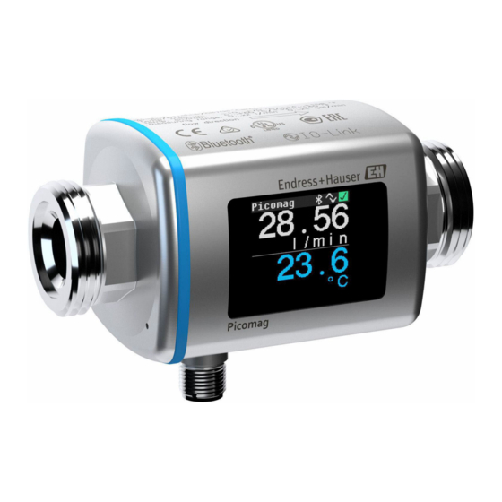
Picomag IO-Link Technical data Materials Component Material Measuring tube PEEK Electrodes, temperature sensor 1.4435/316L Process connection 1.4404/316L Housing 1.4404/316L, 1.4409/CF3M Seal FKM or EPDM Display window Polycarbonate 13.9 Operability Local display The device has an onsite display: Xxxxxxx 28.56 l / min 23.6... -
Page 46: 13.10 Certificates And Approvals
The device meets the legal requirements of the applicable EU Directives. These are listed in the corresponding EU Declaration of Conformity along with the standards applied. Endress+Hauser confirms successful testing of the device by affixing to it the CE mark. UKCA marking The device meets the legal requirements of the applicable UK regulations (Statutory Instruments). -
Page 47: Appendix
Picomag IO-Link Appendix Appendix 14.1 Radio approvals 14.1.1 Argentina CNC ID: C-22455 14.1.2 Brazil ADENDO AO MANUAL Modelo: Picomag 366 8 -1 -07311 A0037714 Para maiores informações, consulte o site da ANATEL: www.gov.br/anatel/pt-br Este equipamento não tem direito à proteção contra interferência prejudicial e não pode causar interferência em sistemas devidamente autorizados. -
Page 48: Indonesia
• This device must accept any interference received, including interference that may cause undesired operation. Changes or modifications made to this equipment not expressly approved by Endress+Hauser Flowtec AG may void the user' s authorization to operate this equipment. Français Le présent appareil est conforme aux CNR d' i ndustrie Canada applicables aux appareils... -
Page 49: Republic Of Korea
R-C-EH7-Picomag 상호 : 한국엔드레스하우저 주식회사 기자재명칭(모델명): 특정소출력 무선기기(무선데이터통신시스템용무선기기) / Picomag 제조국 및 제조국가 : Endress+Hauser Flowtec AG / 프랑스 제조년월 : 제조년월로 표기 *사용자안내문 이 기기는 업무용 환경에서 사용할 목적으로 적합성평가를 받은 기기로서 가정용 환 경에서 사용하는 경우 전파간섭의 우려가 있습니다. -
Page 50: 14.1.12 United Arab Emirates
Appendix Picomag IO-Link A0041612 14.1.12 United Arab Emirates TRA Registered ER68711/19 14.1.13 Other countries Other national approvals are available on request. Endress+Hauser... -
Page 51: Io-Link Process Data
Picomag IO-Link Appendix 14.2 IO-Link process data 14.2.1 Data structure 119… 111… 103… 95… 87… 79… 71… 63… 55… 47… 39… 31… 23… 15… 7…0 number Data Conductivity in µS/cm Totalizer in l Volume flow in l/s Temperature Status in ¹⁄₁₀ °C... -
Page 52: Io-Link Isdu Parameter List
Appendix Picomag IO-Link 14.3 IO-Link ISDU parameter list The individual parts of a parameter description are described in the following section: Designation ISDU ISDU Size Data type Access Value range Factory setting Range (hex) (dec) (byte) limits Identification Device Tag 0x0018 32 (max.) string... - Page 53 Picomag IO-Link Appendix Designation ISDU ISDU Size Data type Access Value range Factory setting Range (hex) (dec) (byte) limits Totalizer Reset 0x016A uint cancel=0 cancel reset=1 System Units Unit Volumeflow 0x0226 uint l/s=0 l/min l/h=5 fl. oz/min=4 m³/h=1 l/min=2 Usgpm=3...
- Page 54 Appendix Picomag IO-Link Designation ISDU ISDU Size Data type Access Value range Factory setting Range (hex) (dec) (byte) limits Output 1 Operating Mode 0x01F4 uint P-Out=0 IO-Link IO-Link is set if connected to a I-Out=1 master S-In=2 S-Out=3 IO-Link=4 U-Out=5...
- Page 55 Picomag IO-Link Appendix Designation ISDU ISDU Size Data type Access Value range Factory setting Range (hex) (dec) (byte) limits Pulse output P-Out Pulse Value 0x03E8 1000 float 0.5/1.0/2.0/10.0 ml 10¯⁹ Unit selection list from Unit 9.9·10⁹ Volume Switch output S-Out 1...
- Page 56 Appendix Picomag IO-Link Designation ISDU ISDU Size Data type Access Value range Factory setting Range (hex) (dec) (byte) limits T-Start-Value 0x02C3 float -10 °C for temperature Unit selection list from Unit Temperature T-End-Value 0x02C4 float +70 °C for temperature Unit selection list from Unit...
- Page 57 Picomag IO-Link Appendix Designation ISDU ISDU Size Data type Access Value range Factory setting Range (hex) (dec) (byte) limits s-End-Value 0x0290 float 1000 -9.9·10⁹ for conductivity 9.9·10⁹ Unit selection list from Unit Conductivity Switch output S-Out 2 Switch Polarity 0x035D...
- Page 58 Appendix Picomag IO-Link Designation ISDU ISDU Size Data type Access Value range Factory setting Range (hex) (dec) (byte) limits T-End-Value 0x02F6 float +70 °C for temperature from Unit Temperature s-Start-Value 0x02F3 float 0 µS/cm for temperature from Conductivity s-End-Value 0x02F4 float 1000 µS/cm...
-
Page 59: Index
Picomag IO-Link Index Index Inspection Received goods ......11 About this document ......5 Intended use . - Page 60 Index Picomag IO-Link Output ....... . . 41 Performance characteristics ....41 Power supply .
- Page 64 *71552010* 71552010 www.addresses.endress.com...