Endress+Hauser Proline Prowirl 73 Operating Instructions Manual
Vortex flow measuring system
Hide thumbs
Also See for Proline Prowirl 73:
- Operating instructions manual (192 pages) ,
- Brief operating instructions (32 pages) ,
- Technical information (25 pages)

Related Manuals for Endress+Hauser Proline Prowirl 73


Summary of Contents for Endress+Hauser Proline Prowirl 73
-
Page 1: Operating Instructions
Operating Instructions Proline Prowirl 73 Vortex Flow Measuring System BA094D/06/en/01.07 71039099 Valid as of software version: V 1.03.XX (Device Software) - Page 2 Brief operating instructions Proline Prowirl 73 Brief operating instructions These brief operating instructions explain how to commission your measuring device quickly and easily: Safety instructions Page 9 Æ Installation Page 15 Æ Wiring Page 25 Æ Display and operating elements Page 35 Æ...
-
Page 3: Quick Setup (Commissioning)
Proline Prowirl 73 QUICK SETUP (commissioning) QUICK SETUP (commissioning) Quick Setup Quick Setup Commissioning Language Select Fluid User defined Saturated Liquid Compressed Superheated Natural gas Water Real gas Water liquid Steam volume volume Steam NX-19 Delta heat Temperature Reference Unit... - Page 4 QUICK SETUP (commissioning) Proline Prowirl 73 Note! The QUICK SETUP COMMISSIONING function is described on Page 105. The display returns to the QUICK SETUP COMMISSIONING cell if you press the ESC key combination X during interrogation. If the fluid selected is changed, the following parameters are reset to their factory settings:...
- Page 5 Proline Prowirl 73 QUICK SETUP (commissioning) Totalizer assignment depends on the fluid selected: Selected fluid: Totalizer 1 assignment Totalizer 2 assignment → Mass flow → Heat flow Saturated steam → Mass flow → Heat flow Superheated steam → Volume flow →...
- Page 6 QUICK SETUP (commissioning) Proline Prowirl 73 Endress+Hauser...
-
Page 7: Table Of Contents
Proline Prowirl 73 Contents Contents Brief operating instructions Operation .......... - Page 8 Contents Proline Prowirl 73 10.1.11 Mechanical construction ... . . 91 10.1.12 Human interface ....92 10.1.13 Certificates and approvals .
-
Page 9: Safety Instructions
• The device must be operated by persons authorized and trained by the facility's owner-operator. Strict compliance with the instructions in these Operating Instructions is mandatory. • Endress+Hauser is willing to assist in clarifying the chemical resistance properties of parts wetted by special fluids, including fluids used for cleaning. However, small changes in temperature, concentration or the degree of contamination in the process can result in changes of the chemical resistance properties. -
Page 10: Return
• Always enclose a fully completed "Declaration of Contamination" form with the device. Only then can Endress+Hauser transport, examine and repair a returned device. • Enclose special handling instructions if necessary, for example a safety data sheet as per European Directive 91/155/EEC. -
Page 11: Identification
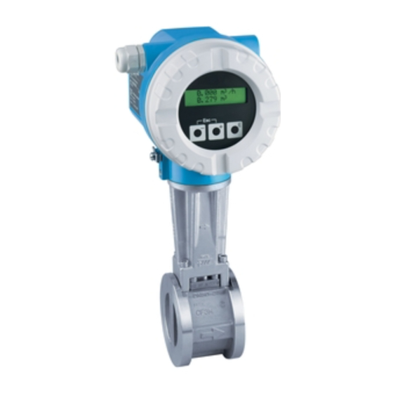
2 Identification Identification Device designation The "Proline Prowirl 73" flowmeter system consists of the following components: • Transmitter Proline Prowirl 73 • Prowirl F or Prowirl W sensor In the compact version, the transmitter and sensor form a mechanical unit; in the remote version they are mounted separate from one another. -
Page 12: Sensor Nameplate (Remote)
2 Identification Proline Prowirl 73 2.1.2 Sensor nameplate (remote) PROWIRL W IP67/NEMA/Type 4X Order Code: 72WXX-XXXXXXXXXXXX 12345678901 2007 Ser.No.: TAG No.: ABCDEFGHJKLMNPQRST DN50 pnom = PS = 10bar / ptest = 20bar Size: 1.0000 P/L K-factor: Meter Body: Materials: CF3M/F316/F316L/1.4404, 316L... -
Page 13: Certificates And Approvals
Regulation and Laboratory Procedures" and the EMC requirements as per IEC/EN 61326. The measuring system described in these Operating Instructions therefore complies with the legal requirements of the EU Directives. Endress+Hauser confirms this by affixing the CE mark to it and by issuing the CE declaration of conformity. - Page 14 2 Identification Proline Prowirl 73 Endress+Hauser...
-
Page 15: Installation
Proline Prowirl 73 3 Installation Installation Incoming acceptance, transport, storage 3.1.1 Incoming acceptance On receipt of the goods, check the following points: • Check the packaging and the contents for damage. • Check the shipment, make sure nothing is missing and that the scope of supply matches your order. -
Page 16: Installation Conditions
3 Installation Proline Prowirl 73 Installation conditions Note the following points: • The measuring device requires a fully developed flow profile as a prerequisite for correct volume flow measurement. The inlet and outlet runs must be taken into account (see Page 19). -
Page 17: Orientation
Proline Prowirl 73 3 Installation 3.2.2 Orientation The device can be installed basically in any orientation. Please consider the following, however (Fig. 6): • In the case of liquids, there should be upward flow in vertical pipes to avoid partial pipe filling (see orientation A). -
Page 18: Heat Insulation
3 Installation Proline Prowirl 73 3.2.3 Heat insulation Some fluids require suitable measures to avoid heat transfer at the sensor to ensure optimum temperature measurement and mass calculation. A wide range of materials can be used to provide the required insulation. -
Page 19: Inlet And Outlet Run
Proline Prowirl 73 3 Installation 3.2.4 Inlet and outlet run As a minimum, the inlet and outlet runs shown below must be observed to achieve the specified accuracy of the device. The longest inlet run shown must be observed if two or more flow disturbances are present. -
Page 20: Vibrations
Proline Prowirl 73 Perforated plate flow conditioner A specially designed perforated plate flow conditioner, available from Endress+Hauser, can be installed if it is not possible to observe the inlet runs required. The flow conditioner is fitted between two piping flanges and centered with mounting bolts. Generally, this reduces the inlet run required to 10 ×... -
Page 21: Installation
Seals projecting into the flow current have a negative effect on the vortex formation after the bluff body and cause inaccurate measurement. The gaskets provided by Endress+Hauser for the wafer version have therefore an inner diameter with a bigger inner diameter than the piping. -
Page 22: Rotating The Transmitter Housing
3 Installation Proline Prowirl 73 3.3.2 Rotating the transmitter housing The electronics housing can be rotated continuously 360° on the housing support. Loosen the safety screw. Turn the transmitter housing to the desired position (max. 180° in each direction to the stop). -
Page 23: Mounting Transmitter (Remote)
Proline Prowirl 73 3 Installation 3.3.4 Mounting transmitter (remote) The transmitter can be mounted in the following ways: • Wall mounting • Pipe mounting (with separate mounting kit, accessories → Page 59) The transmitter and the sensor must be mounted separate in the following circumstances: •... -
Page 24: Post-Installation Check
3 Installation Proline Prowirl 73 Post-installation check Perform the following checks after installing the measuring device in the piping: Device condition and specifications Notes Is the device damaged (visual inspection)? Do the process temperature/pressure, ambient temperature, measuring range see Page 81 ff. -
Page 25: Wiring
Warning: When connecting Ex-certified devices, please refer to the notes and diagrams in the Ex-specific supplement to these Operating Instructions. Please do not hesitate to contact your Endress+Hauser representative if you have any questions. Connecting the remote version 4.1.1 Connecting the sensor Note: •... -
Page 26: Cable Specifications
4 Wiring Proline Prowirl 73 4.1.2 Cable specifications The specifications of the cable connecting the transmitter and the sensor of the remote version are as follows: • 4 × 2 × 0.5 mm (AWG 20) PVC cable with common shield (4 pairs, pair-stranded). - Page 27 Proline Prowirl 73 4 Wiring Procedure for connecting the transmitter, Non-Ex, Ex i/IS and Ex n version (Fig. 16) Unscrew the cover (a) of the electronics compartment from the transmitter housing. Remove the display module (b) from the retaining rails (c) and refit onto right retaining rail with the left side (this secures the display module).
- Page 28 4 Wiring Proline Prowirl 73 Procedure for connecting the transmitter, Ex d/XP version (Fig. 17) Note: When connecting Ex-certified devices, please refer to the notes and diagrams in the Ex-specific supplement to these Operating Instructions. Open the clamp (a) securing the cover of the connection compartment.
- Page 29 Proline Prowirl 73 4 Wiring Wiring diagram A0001897 Fig. 18: Assignment of terminals Power supply/current output Optional frequency output, can also be operated as: - Pulse or status output - Together with flow computer RMC or RMS621 as PFM output (see below)
- Page 30 4 Wiring Proline Prowirl 73 Connecting diagram for the input of an external temperature or pressure value via HART protocol Note: • Set-up and commissioning of external temperature/pressure sensors → Page 56. • In the following drawings the pulse/frequency output remains available. It can be used for the output of e.g.
-
Page 31: Terminal Assignment
Proline Prowirl 73 4 Wiring Connecting diagram without process control system – – 250 W 0– 0– I– I– A0001776 Fig. 22: Connection diagram without PLC Dotted line = wiring without connection to external components (e.g. recorder, displays, Fieldgate, etc.) -
Page 32: Hart Connection
4 Wiring Proline Prowirl 73 4.2.3 HART connection Users have the following connection options at their disposal: • Direct connection to transmitter by means of terminals 1 (+) / 2 (–) • Connection across the 4 to 20 mA loop. -
Page 33: Degree Of Protection
• The housing seals must be clean and undamaged when inserted into their grooves. The seals must be dried, cleaned or replaced if necessary. If the device is used in a dust atmosphere, only the associated Endress+Hauser housing seals can be used. • All housing screws and screw caps must be firmly tightened. -
Page 34: Endress+Hauser
4 Wiring Proline Prowirl 73 Endress+Hauser... -
Page 35: Operation
Proline Prowirl 73 5 Operation Operation Display and operating elements The local operation enables you to read important parameters directly at the measuring point and also configure the device. The display consists of two lines; this is where measured values and/or status variables (e.g. bar graph) are displayed. -
Page 36: The Function Matrix: Layout And Use
5 Operation Proline Prowirl 73 The function matrix: layout and use Note: • Please refer to the general notes on Page 37. • Function matrix overview → Page 97 • Detailed description of all functions → Page 98 ff. The function matrix is a two-level construct: the function groups form one level and the groups' functions the other. -
Page 37: General Notes
• If "0" is entered as the private code, programming is always enabled. • Your Endress+Hauser service organisation can be of assistance if you mislay your private code. 5.2.3 Disabling the programming mode Programming mode is disabled if you do not press a key within 60 seconds following automatic return to the HOME position. -
Page 38: Error Message Display
5 Operation Proline Prowirl 73 Error message display Type of error Errors which occur during commissioning or measuring operation are displayed immediately. If two or more system or process errors occur, the error with the highest priority is always the one shown on the display. The measuring system distinguishes between two types of error: •... -
Page 39: Operating Options
Proline Prowirl 73 5 Operation terminal or PC-based operating programs (such as Fieldtool), require device description (DD) files. They are used to access all the information in a HART device. Such information is transferred solely via "commands". There are three different command classes: •... -
Page 40: Current Device Description Files
The "Fieldcheck" tester/simulator is used for testing flowmeters in the field. When used in conjunction with the "ToF Tool - Fieldtool Package" software package, test results can be imported into a database, printed and used for official certification. Contact your Endress+Hauser representative for more information. Endress+Hauser... -
Page 41: Device Variables And Process Variables
Proline Prowirl 73 5 Operation 5.4.3 Device variables and process variables Device variables: The following device variables are available via the HART protocol: ID (decimal) Device variable OFF (not assigned) Volume flow Temperature Mass flow Corrected volume flow Heat flow... -
Page 42: Universal / Common Practice Hart Commands
Access type = Read The response consists of a 12-byte device ID: – Byte 0: fixed value 254 – Byte 1: manufacturer ID, 17 = Endress+Hauser – Byte 2: device type ID, 56 = Prowirl 73 – Byte 3: number of preambles –... - Page 43 Access type = Read device: – Byte 0: fixed value 254 – Byte 1: manufacturer ID, 17 = Endress+Hauser – Byte 2: device type ID, 56 = Prowirl 73 – Byte 3: number of preambles – Byte 4: rev. no. universal commands –...
- Page 44 – Byte 7-10: start of measuring range, value for 4 mA – Byte 11-14: attenuation constant in [s] – Byte 15: ID for write protection – Byte 16: ID for OEM dealer, 17 = Endress+Hauser Primary process variable = volume flow Note: Manufacturer-specific units are represented using the HART unit ID "240".
- Page 45 Proline Prowirl 73 5 Operation Command no. Command data Response data HART command / access type (numeric data in decimal form) (numeric data in decimal form) Device status reset None None "configuration changed" Access = Write Simulate output current of the...
- Page 46 5 Operation Proline Prowirl 73 Command no. Command data Response data HART command / access type (numeric data in decimal form) (numeric data in decimal form) Write assignments of the device Set the device variables to the four process The current variable assignment of the process variables is displayed...
-
Page 47: Device Status / Error Messages
Proline Prowirl 73 5 Operation 5.4.5 Device status / error messages You can read the extended device status, in this case, current error messages, via command 48. The command delivers bit-encoded information (see table below). Note: Detailed information on the device status messages and error messages, and how they are rectified, can be found on Page 64 ff.! - Page 48 5 Operation Proline Prowirl 73 Short error description ( → Page 64 ff.) Byte Bit Error no. Not assigned – Not assigned – Not assigned – Current adjustment active Device test active Not assigned – Not assigned – Not assigned –...
- Page 49 Proline Prowirl 73 5 Operation Short error description ( → Page 64 ff.) Byte Bit Error no. The checksum of the HART telegram is incorrect. The time out for the reception of HART telegrams has been exceeded. An algebraic sign different from the expected has been measured for the delta heat.
-
Page 50: Switching Hart Write Protection On/Off
5 Operation Proline Prowirl 73 5.4.6 Switching HART write protection on/off A DIP switch on the amplifier board provides the means of activating or deactivating the HART write protection. If HART write protection is enabled, it is not possible to change parameters via the HART protocol. -
Page 51: Commissioning
Proline Prowirl 73 6 Commissioning Commissioning Function check Make sure that all final checks have been completed before you commission your measuring point: • "Post-installation check" checklist → Page 24 • "Post-connection check" checklist → Page 33 Commissioning 6.2.1 Switching on the measuring device Once the function checks have been successfully completed, it is time to switch on the supply voltage. -
Page 52: Installation Of A New Electronics Print
6 Commissioning Proline Prowirl 73 6.2.2 Installation of a new electronics print After start-up the device checks whether a serial number is present. If this is not the case, the fol- lowing setup is started. How to install a new electronics print is described on Page 75 ff. -
Page 53: Commissioning" Quick Setup
Proline Prowirl 73 6 Commissioning 6.2.3 "Commissioning" Quick Setup The "Commissioning" Quick Setup guides you systematically through all the major functions of the device that have to be configured for standard measuring operation. Quick Setup Quick Setup Commissioning Language Select Fluid... - Page 54 6 Commissioning Proline Prowirl 73 Note! The QUICK SETUP COMMISSIONING function is described on Page 105. The display returns to the QUICK SETUP COMMISSIONING cell if you press the ESC key combination X during interrogation. If the fluid selected is changed, the following parameters are reset to their factory settings:...
- Page 55 Proline Prowirl 73 6 Commissioning Totalizer assignment depends on the fluid selected: Selected fluid: Totalizer 1 assignment Totalizer 2 assignment → Mass flow → Heat flow Saturated steam → Mass flow → Heat flow Superheated steam → Volume flow → Heat flow Water →...
-
Page 56: External Pressure/Temperature Sensors
Switch on burst mode switching on the function 3 HART OUTPUT / 3 BURST MODE to ON and chosing in the function 3 HART OUTPUT / 4 BURST OPTION either "PV" or "Process vars/crnt.". – Cerabar S (pressure) → using the Endress+Hauser software "ToF Tool Fieldtool-Package" or "FieldCare". Note: –... -
Page 57: Maintenance
The housing seals must be clean and undamaged when inserted into their grooves. The seals must be dried, cleaned or replaced if necessary. Note: If the device is used in a dust atmosphere, only the associated Endress+Hauser housing seals can be used. Endress+Hauser... -
Page 58: 7 Maintenance
7 Maintenance Proline Prowirl 73 Endress+Hauser... -
Page 59: Accessories
Proline Prowirl 73 8 Accessories Accessories Various accessories, which can be ordered separately from Endress+Hauser, are available for the transmitter and the sensor. Your Endress+Hauser service organisation can provide detailed information on the order codes in question. Accessory Description Order code 73XXX −... - Page 60 When used in conjunction with the "ToF Tool - Fieldtool Package" software package, test results can be imported into a database, printed and used for official certification. Contact your Endress+Hauser representative for more information. PMC131 − **** Pressure transducer Cerabar T is used to measure the absolute and gauge pressure of PMP131 −...
- Page 61 Proline Prowirl 73 8 Accessories Accessory Description Order code FXA520 − **** Fieldgate FXA520 Gateway to remote interrogation of HART sensors and actuators via Web browser: • Web server for remote monitoring of up to 30 measuring points • Intrinsically safe version [EEx ia]IIC for applications in hazardous areas •...
- Page 62 8 Accessories Proline Prowirl 73 Endress+Hauser...
-
Page 63: Trouble-Shooting
Proline Prowirl 73 9 Trouble-shooting Trouble-shooting Trouble-shooting instructions Always start trouble-shooting with the checklists below if faults occur after start-up or during operation. This takes you directly (via various queries) to the cause of the problem and the appropriate remedial measures. -
Page 64: System Error Messages
9 Trouble-shooting Proline Prowirl 73 System error messages " Caution: In the event of a serious fault, a flowmeter might have to be returned to the manufacturer for repair. In such cases, the procedures on Page 10 must be carried out before you return the measuring device to Endress+Hauser. - Page 65 Proline Prowirl 73 9 Trouble-shooting Type Error message / No. Cause Remedy / spare part SHORT C. PT DSC The temperature sensor is faulty. Contact your Endress+Hauser service # 313 Temperature measurement becomes organisation. inaccurate and total failure of the temperature sensor (#316) must be reckoned with.
- Page 66 (e.g. flow is above measuring range which means that the flow may have to be reduced) If the checks do not solve the problem, please contact your Endress+Hauser service organisation. Endress+Hauser...
- Page 67 Proline Prowirl 73 9 Trouble-shooting Type Error message / No. Cause Remedy / spare part T ELECTR. MIN. The limit value for the minimum • Check whether the device has been # 397 permissible ambient temperature is correctly insulated (see Page 18).
- Page 68 9 Trouble-shooting Proline Prowirl 73 Type Error message / No. Cause Remedy / spare part HART-IN: NO VAL. The HART input functionality is activated, • Check if the pressure, temperature or # 520 but the designated value (e.g. pressure density sensor is value) is not found in the HART message.
- Page 69 Proline Prowirl 73 9 Trouble-shooting Type Error message / No. Cause Remedy / spare part DEV. TEST ACT. The measuring device is being checked on – # 698 site via the test and simulation device. CURR. ADJUST Current adjustment is active.
-
Page 70: Process Error Messages
9 Trouble-shooting Proline Prowirl 73 Process error messages Process errors can be defined as either "Fault" or "Notice" messages and can thereby be weighted differently. Determination of this is done via the function matrix ( → Page 162, Function ERROR CATEGORY). -
Page 71: Process Errors Without Messages
• Support the piping near the device. If these measures do not solve the problem, your Endress+Hauser service organisation can adjust the filters of the device to suit your special application. - Page 72 The following options are available for tackling problems of this nature: some other fault not described above has occurred. Request the services of an Endress+Hauser service technician In these instances, please contact If you contact our service organisation to have a service technician sent out, please...
-
Page 73: Response Of Outputs To Errors
Proline Prowirl 73 9 Trouble-shooting Response of outputs to errors Note: The failsafe mode of the totalizers and the current, pulse and frequency outputs can be configured by means of various functions in the function matrix. Positive zero return and error response: You can use positive zero return to set the signals of the current, pulse and frequency outputs to their fallback value, for example when operation has to be interrupted while a pipe is being cleaned. -
Page 74: Spare Parts
Note: You can order spare parts directly from your Endress+Hauser service organisation by quoting the serial number printed on the transmitter nameplate (see Page 11). Spare parts are shipped as sets comprising the following parts: •... -
Page 75: Installing And Removing Electronics Boards
Use a workplace with a grounded working surface, purpose-built for electrostatically sensitive devices! " Caution: Use only genuine Endress+Hauser parts. Procedure when installing/removing electronics boards (see Fig. 32) Unscrew the cover (a) of the electronics compartment from the transmitter housing. Remove the local display module (b) from the retaining rails (c). - Page 76 9 Trouble-shooting Proline Prowirl 73 A0001919 Fig. 32: Installing and removing electronics boards Non-Ex / Ex i/IS and Ex nversion Cover of electronics compartment Local display module Retaining rails of local display module Fixing screws for cover of connection compartment...
-
Page 77: Ex D/Xp Version
" Caution: Use only genuine Endress+Hauser parts. Procedure when installing/removing electronics boards (see Fig. 33) Installing/removing the I/O board (COM module) Release securing clamp (a) of the connection compartment cover (b). - Page 78 9 Trouble-shooting Proline Prowirl 73 A0001920 Fig. 33: Installing and removing electronics boards Ex-d version Clamp for cover of connection compartment Cover of connection compartment Terminal connector I/O board (COM module) threaded connection I/O board (COM module) Connecting cable plug I/O-module...
-
Page 79: Software History
Proline Prowirl 73 9 Trouble-shooting Software history Date Software version Software modification Documentation Amplifier 01.2007 V 1.03.00 Software extension: 71039099/01.07 – Flanged devices with reduced inner diameter (R Type, S Type) New functionalities: – Device software displayed (NAMUR Recommendation NE 53) –... - Page 80 9 Trouble-shooting Proline Prowirl 73 Endress+Hauser...
-
Page 81: Technical Data
Proline Prowirl 73 10 Technical data Technical data 10.1 Technical data at a glance 10.1.1 Application The measuring system is used to measure the flow of saturated steam, superheated steam, gases and liquids. The measured variables volume flow and temperature are measured primarily. From these values, the device can used stored data on the density and enthalpy to calculate and output the mass flow and heat flow for example. - Page 82 – Nominal diameters larger than DN 100 (4") Note! By using the selection and planning program "Applicator", you can determine the exact values for the fluid you use. You can obtain the Applicator from your Endress+Hauser sales centre or on the Internet under www.endress.com. K-factor range The table is used for orientation purposes.
-
Page 83: Output
Proline Prowirl 73 10 Technical data 10.1.4 Output Outputs, general The following measured variables can generally be output via the outputs: Current output Freq. output Pulse output Status output Limit value Volume flow If configured If configured If configured (flow or totalizer) - Page 84 10 Technical data Proline Prowirl 73 • Vortex frequency: – Unscaled vortex pulses directly output 0.5 to 2850 Hz (e.g. for connecting to a flow computer RMC621) – Pulse ratio 1:1 • PFM signal (pulse/frequency modulation): For external connection with flow computer RMC or RMS621 (see Page 29).
-
Page 85: Power Supply
Proline Prowirl 73 10 Technical data 10.1.5 Power supply Electrical connection see Page 25 ff. Supply voltage Non-Ex: 12 to 36 V DC (with HART: 18 to 36 V DC) Ex i/IS and Ex n: 12 to 30 V DC (with HART 18 to 30 V DC) -
Page 86: Operating Conditions: Installation
10 Technical data Proline Prowirl 73 Flange connection: DN 15 (½"): ±20% of the internal diameter DN 25 (1"): ±15% of the internal diameter DN 40 (1½"): ±12% of the internal diameter DN ≥ 50 (2"): ±10% of the internal diameter Wafer: DN 15 (½"): ±15% of the internal diameter... -
Page 87: Operating Conditions: Process
Proline Prowirl 73 10 Technical data Remote version transmitter • Standard: –40 to +80 °C (–40 to +176 °F) • EEx d/XP version: –40 to +60 °C (–40 to +140 °F) • ATEX II 1/2 GD version/dust ignition-proof: –20 to +55 °C (–4 to +131 °F) •... - Page 88 10 Technical data Proline Prowirl 73 Medium pressure Pressure-temperature curve to EN (DIN), stainless steel PN 10 to 40 → Prowirl 73W and 73F PN 63 to 160 → Prowirl 73F (in development) [psi] [bar] [psi] [bar] 3000 PN 40...
-
Page 89: Frequency Ranges For Air And Water
Proline Prowirl 73 10 Technical data 10.1.10 Frequency ranges for air and water For further media, e.g. steam, you can find information in the Applicator. Prowirl 73W (SI units) DN (DIN) Air (at 0 °C, 1.013 bar) Water (at 20 °C) - Page 90 10 Technical data Proline Prowirl 73 Prowirl 73F (SI units) DN (DIN) Air (at 0 °C, 1.013 bar) Water (at 20 °C) K-factor Corrected volume flow (e) in [m Volume flow (e) in [m [Pulse/dm Frequency range Frequency range min. to max.
-
Page 91: Mechanical Construction
Proline Prowirl 73 10 Technical data 10.1.11 Mechanical construction Design, dimensions See Technical Information TI070D/06/en Weight See Technical Information TI070D/06/en Material Transmitter housing • Powder-coated die-cast aluminum AlSi10Mg – in accordance with EN 1706/EN AC-43400 (EEx d/XP version: cast aluminum EN 1706/... -
Page 92: Human Interface
• Operating elements accessible also in Ex zones Remote operation Operation via: • HART protocol • ToF Tool - Fieldtool Package (software package from Endress+Hauser for complete configuration, commissioning and diagnosis) 10.1.13 Certificates and approvals CE approval see Page 13... -
Page 93: Ordering Information
10.1.15 Accessories Various accessories, which can be ordered separately from Endress+Hauser, are available for the transmitter and the sensor (see Page 59). Your Endress+Hauser service organisation can provide detailed information on the order codes of your choice. -
Page 94: Dimensions Of Flow Conditioner
10 Technical data Proline Prowirl 73 10.2 Dimensions of flow conditioner Dimensions according to: • EN 1092-1 (DIN 2501) • ANSI B16.5 • JIS B2238 Material 1.4435 (316L), in conformity with NACE MR0175-2003 and MR0103-2003 A0001941 D1: The flow conditioner is fitted at the outer diameter between the bolts. - Page 95 Proline Prowirl 73 10 Technical data Dimensions of flow conditioner according to ANSI Pressure Centering diameter D1 / D2 * Weight rating mm (inch) mm (inch) kg (lbs) Cl. 150 50.1 (1.97) 0.03 (0.07) ½" 2.0 (0.08) Cl. 300 56.5 (2.22) 0.04 (0.09)
- Page 96 10 Technical data Proline Prowirl 73 Dimensions of flow conditioner according to JIS Pressure Centering diameter D1 / D2 * Weight rating [mm] [mm] [kg] 60.3 0.06 60.3 0.06 66.3 0.06 76.3 0.14 76.3 0.14 81.3 0.14 91.3 0.31 91.3 0.31...
-
Page 97: Description Of Device Functions
Proline Prowirl 73 11 Description of device functions Description of device functions 11.1 Illustration of the function matrix Endress+Hauser... -
Page 98: Description Of Functions
11 Description of device functions Proline Prowirl 73 11.2 Description of functions 11.2.1 Group MEASURED VALUES Function description MEASURED VALUES VOLUME FLOW The volume flow currently measured appears on the display. Display: 5-digit floating-point number, including unit (e.g. 5.5445 dm /min;... - Page 99 Proline Prowirl 73 11 Description of device functions Function description MEASURED VALUES HEAT FLOW Note: This value is not available unless the SATURATED STEAM, SUPERHEATED STEAM or WATER option was selected in the SELECT FLUID function (Page 142). "– – – –"...
- Page 100 11 Description of device functions Proline Prowirl 73 Function description MEASURED VALUES CALCULATED Note: SATURATED STEAM This function is not available unless the SATURATED STEAM option was selected in the PRESSURE SELECT FLUID function (Page 142) . The calculated steam pressure (of the saturated steam) appears on the display.
-
Page 101: Group System Units
Proline Prowirl 73 11 Description of device functions 11.2.2 Group SYSTEM UNITS Function description SYSTEM UNITS UNIT VOLUME FLOW For selecting the unit required and displayed for the volume flow. The unit you select here is also valid for: • Flow display •... - Page 102 11 Description of device functions Proline Prowirl 73 Function description SYSTEM UNITS UNIT MASS FLOW For selecting the unit required and displayed for the calculated mass flow. The unit you select here is also valid for: • Flow display • Current output (value 20 mA) •...
- Page 103 Proline Prowirl 73 11 Description of device functions Function description SYSTEM UNITS UNIT HEAT FLOW For selecting the unit required and displayed for the heat flow. Note: The following units of time can be selected: s = second, m = minute, h = hour, d = day...
- Page 104 11 Description of device functions Proline Prowirl 73 Function description SYSTEM UNITS UNIT PRESSURE For selecting the unit required and displayed for the pressure and the relative pressure unit. Options: bara (bar absolute) psia (pounds per square inch absolute) kPa a (Kilopascal absolute)
-
Page 105: Group Quick Setup
Proline Prowirl 73 11 Description of device functions 11.2.3 Group QUICK SETUP Function description QUICK SETUP QUICK SETUP Use this function to start the Quick Setup for commissioning. COMMISSIONING Options: Factory setting: Note: Please refer to Page 53 for a detailed description of the "Commissioning" Quick Setup menu. -
Page 106: Group Operation
HOME position. • You can also disable programming in this function by entering any number (other than the private code). • The Endress+Hauser service organisation can be of assistance if you mislay your private code. DEFINE PRIVATE CODE Use this function to specify the private code for enabling programming. - Page 107 Proline Prowirl 73 11 Description of device functions Function description OPERATION STATUS ACCESS The access status for the function matrix appears on the display. Display: ACCESS CUSTOMER (parameters can be modified) LOCKED (parameters cannot be modified) ACCESS CODE The number of times the private and service code was entered to access the device COUNTER appears on the display.
-
Page 108: Group User Interface
11 Description of device functions Proline Prowirl 73 11.2.5 Group USER INTERFACE Function description USER INTERFACE ASSIGN LINE 1 For selecting the display value for the main line (top line of the local display) which should be displayed during normal operation. - Page 109 Proline Prowirl 73 11 Description of device functions Function description USER INTERFACE ASSIGN LINE 2 For selecting the display value for the additional line (bottom line of the local display) which should be displayed during normal operation. Options: VOLUME FLOW...
- Page 110 11 Description of device functions Proline Prowirl 73 Function description USER INTERFACE 100% VALUE LINE 2 Note: This function is not available unless one of the following was selected in the ASSIGN LINE 2 function. • VOLUME FLOW IN % •...
- Page 111 Proline Prowirl 73 11 Description of device functions Function description USER INTERFACE CONTRAST LCD Use this function to optimise the display contrast to suit local operating conditions. User input: 10 to 100% Factory setting: Note: If you press the P keys simultaneously at startup, the language defaults to "ENGLISH"...
-
Page 112: Group Totalizers 1 And 2
11 Description of device functions Proline Prowirl 73 11.2.6 Group TOTALIZERS 1 and 2 Function description TOTALIZER ASSIGN TOTALIZER Use this function to assign a measured variable to the totalizer. Options (totalizer 1 and 2): VOLUME FLOW MASS FLOW CORRECTED VOLUME FLOW... - Page 113 Proline Prowirl 73 11 Description of device functions Function description TOTALIZER UNIT TOTALIZER Use this function to define the unit for the totalizer. Depending on what is selected in the ASSIGN TOTALIZER function (see Page 112), only the associated units are offered for selection here.
- Page 114 11 Description of device functions Proline Prowirl 73 Function description TOTALIZER RESET TOTALIZER Use this function to reset the sum and the overflow of the totalizer to 0 (= RESET). Options: Factory setting: Endress+Hauser...
-
Page 115: Group Handling Totalizer
Proline Prowirl 73 11 Description of device functions 11.2.7 Group HANDLING TOTALIZER Function description HANDLING TOTALIZER RESET ALL TOTALIZERS Use this function to reset the sum and the overflow of both totalizers to 0 (= RESET). Options: Factory setting: FAILSAFE MODE Use this function to define the response of both totalizers to an alarm condition. -
Page 116: Group Current Output
11 Description of device functions Proline Prowirl 73 11.2.8 Group CURRENT OUTPUT Function description CURRENT OUTPUT ASSIGN CURRENT Use this function to assign a measured variable to the current output. Options: VOLUME FLOW TEMPERATURE MASS FLOW CORRECTED VOLUME FLOW HEAT FLOW... - Page 117 Proline Prowirl 73 11 Description of device functions Function description CURRENT OUTPUT FAILSAFE MODE The dictates of safety render it advisable to ensure that the current output assumes a predefined state in the event of a fault. Use this function to define the response of the current output to fault.
- Page 118 11 Description of device functions Proline Prowirl 73 Function description CURRENT OUTPUT VALUE SIMULATION Note: CURRENT This function is not available unless the ON option was selected in the SIMULATION CURRENT function. Use this function to define a selectable value (e.g. 12 mA). This value is used to test downstream devices and the measuring device itself.
-
Page 119: Group Frequency Output
Proline Prowirl 73 11 Description of device functions 11.2.9 Group FREQUENCY OUTPUT Note: The frequency output can also be operated as a pulse or status output. Function description FREQUENCY OUTPUT OPERATING MODE Use this function to specify whether the output functions as a frequency output, pulse output or status output. - Page 120 11 Description of device functions Proline Prowirl 73 Function description FREQUENCY OUTPUT START VALUE Note: FREQUENCY This function is not available unless the FREQUENCY option was selected in the OPERATING MODE function. Use this function to define a start frequency for the frequency output. You specify the associated measured value of the measuring range in the VALUE-f LOW function on Page 121.
- Page 121 Proline Prowirl 73 11 Description of device functions Function description FREQUENCY OUTPUT VALUE-f LOW Note: This function is not available unless the FREQUENCY option was selected in the OPERATING MODE function. Use this function to assign a value to the start frequency (see Page 120). The value entered here must be smaller than the value assigned to the VALUE-f HIGH.
- Page 122 11 Description of device functions Proline Prowirl 73 Function description FREQUENCY OUTPUT OUTPUT SIGNAL Note: This function is not available unless the FREQUENCY option was selected in the OPERATING MODE function. For selecting the output configuration of the pulse output.
- Page 123 Proline Prowirl 73 11 Description of device functions Function description FREQUENCY OUTPUT OUTPUT SIGNAL Example for output configuration PASSIVE-POSITIVE: (contd.) Output configuration with an external pull-down resistance. In the quiescent state (at zero flow), a positive voltage level is measured via the pull-down resistance.
- Page 124 11 Description of device functions Proline Prowirl 73 Function description FREQUENCY OUTPUT TIME CONSTANT Note: This function is not available unless the FREQUENCY option was selected in the OPERATING MODE function. Use this function to enter a time constant defining how the frequency output signal reacts to severely fluctuating measured variables, either very quickly (enter a low time constant) or with damping (enter a high time constant).
- Page 125 Proline Prowirl 73 11 Description of device functions Function description FREQUENCY OUTPUT SIMULATION Note: FREQUENCY This function is not available unless the FREQUENCY option was selected in the OPERATING MODE function. Use this function to activate simulation of the frequency output.
- Page 126 11 Description of device functions Proline Prowirl 73 Function description PULSE OUTPUT ASSIGN PULSE Note: This function is not available unless the PULSE option was selected in the OPERATING MODE function. Use this function to assign a measured variable to the pulse output.
- Page 127 Proline Prowirl 73 11 Description of device functions Function description PULSE OUTPUT PULSE WIDTH Note: This function is not available unless the PULSE option was selected in the OPERATING MODE function. Use this function to enter the maximum pulse width of the output pulses.
- Page 128 11 Description of device functions Proline Prowirl 73 Function description PULSE OUTPUT OUTPUT SIGNAL Note: This function is not available unless the PULSE option was selected in the OPERATING MODE function. For selecting the output configuration of the pulse output.
- Page 129 Proline Prowirl 73 11 Description of device functions Function description PULSE OUTPUT OUTPUT SIGNAL Example for output configuration PASSIVE-POSITIVE: (contd.) Output configuration with an external pull-down resistance. In the quiescent state (at zero flow), a positive voltage level is measured via the pull-down resistance.
- Page 130 11 Description of device functions Proline Prowirl 73 Function description PULSE OUTPUT FAILSAFE MODE Note: This function is not available unless the PULSE option was selected in the OPERATING MODE function. The dictates of safety render it advisable to ensure that the pulse output assumes a predefined state in the event of a fault.
- Page 131 Proline Prowirl 73 11 Description of device functions Function description PULSE OUTPUT SIMULATION PULSE Factory setting: (contd.) Note: • The notice message #631 "SIM. PULSE" (see Page 68) indicates that simulation is active. • The on/off ratio is 1:1 for both types of simulation.
- Page 132 11 Description of device functions Proline Prowirl 73 Function description STATUS OUTPUT ASSIGN STATUS Note: This function is not available unless the STATUS option was selected in the OPERATING MODE function. Use this function to assign a switching function to the status output.
- Page 133 Proline Prowirl 73 11 Description of device functions Function description STATUS OUTPUT SWITCH-ON POINT Note: This function is not available unless a limit value was selected in the OPERATING MODE function. Use this function to assign a value to the switch-on point (status output closed).
- Page 134 11 Description of device functions Proline Prowirl 73 Function description STATUS OUTPUT SWITCH-OFF POINT Note: This function is not available unless a limit value was selected in the ASSIGN STATUS function. Use this function to assign a value to the switch-off point (status output open).
- Page 135 Proline Prowirl 73 11 Description of device functions Function description STATUS OUTPUT ACTUAL STATUS Note: OUTPUT This function is not available unless the STATUS option was selected in the OPERATING MODE function. The current status of the status output appears on the display.
-
Page 136: Response Of The Status Output
11 Description of device functions Proline Prowirl 73 11.2.10 Response of the status output General information If you have configured the status output for "LIMIT VALUE", you can specify the required switch points in the SWITCH-ON POINT and SWITCH-OFF POINT functions. When the measured variable in question reaches these predefined values, the status output switches as shown in the illustrations below. -
Page 137: Group Communication
Proline Prowirl 73 11 Description of device functions 11.2.11 Group COMMUNICATION Function description COMMUNICATION TAG NAME Use this function to enter a tag name for the measuring device. You can edit and read this tag name via the local display or the HART protocol. - Page 138 BURST MODE function. MANUFACTURER ID The manufacturer number in decimal numerical format appears on the display. Display: 17 = (11 hex) for Endress+Hauser DEVICE ID The instrument number in hexadecimal numerical format appears on the display. Display: 57 = (87 dec) for Prowirl 73...
-
Page 139: Group Process Parameter
Proline Prowirl 73 11 Description of device functions 11.2.12 Group PROCESS PARAMETER Function description PROCESS PARAMETER D MATING PIPE The device has diameter step correction. This can be activated by entering the actual value of the mating pipe (see Fig., d1) in this parameter. - Page 140 11 Description of device functions Proline Prowirl 73 Function description PROCESS PARAMETER ASSIGN LOW FLOW CUT For selecting the process variable on which low flow cut off should act. Options: – OFF – VOLUME FLOW – MASS FLOW – CORRECTED VOLUME FLOW –...
- Page 141 Proline Prowirl 73 11 Description of device functions Function description PROCESS PARAMETER OFF-VALUE LOW FLOW Use this function to enter the off-value (b) for low flow cut off. Enter the off-value as a CUT OFF positive hysteresis (H) from the on-value (a).
-
Page 142: Group Flow Computer
11 Description of device functions Proline Prowirl 73 11.2.13 Group FLOW COMPUTER Function description FLOW COMPUTER SELECT FLUID Note: We recommend you only change the fluid selected by means of the Commissioning Quick Setup (see Page 53). In the Commissioning Quick Setup, you can adjust all the relevant parameters to suit the newly selected fluid. - Page 143 Proline Prowirl 73 11 Description of device functions Function description FLOW COMPUTER SELECT FLUID Example of application: (contd.) RMC 621 A0001983 Selected fluid → SUPERHEATED STEAM Applications: Calculation of steam flow and steam enthalpy it contains at the output of a steam generator or an individual consumer.
- Page 144 11 Description of device functions Proline Prowirl 73 Function description FLOW COMPUTER Selected fluid → WATER SELECT FLUID (contd.) Applications: Calculation of the enthalpy in a flow of water, e.g. to determine the residual heat in the return of a heat exchanger.
- Page 145 Proline Prowirl 73 11 Description of device functions Function description FLOW COMPUTER Selected fluid → REAL GAS (nitrogen, CO SELECT FLUID , etc.), COMPRESSED AIR or (contd.) NATURAL GAS NX-19 Applications: Calculation of the mass flow and the corrected volume flow of gases.
- Page 146 11 Description of device functions Proline Prowirl 73 Function description FLOW COMPUTER Selected fluid → SATURATED STEAM DELTA HEAT SELECT FLUID (contd.) Note: This selection requires the import of a temperature value of a • HART compatible and • in the Burst mode working external temperature transmitter via the HART input functionality of Prowirl 73.
- Page 147 Proline Prowirl 73 11 Description of device functions Function description FLOW COMPUTER Selected fluid → WATER DELTA HEAT SELECT FLUID (contd.) Note: This selection requires the import of a temperature value of a • HART compatible and • in the Burst mode working external temperature transmitter via the HART input functionality of Prowirl 73.
- Page 148 11 Description of device functions Proline Prowirl 73 Function description FLOW COMPUTER ERROR -> Use this function to enter a fixed default valve should the temperature meaurement, TEMPERATURE within the BSC sensor, fail. If temperature measurement fails, the device continues to work with the temperature value entered here.
- Page 149 • If the value in this function is changed, we recommend you reset the totalizers. • You can determine the expansion coefficient with the aid of the Applicator ("Fluid Properties" tab). Applicator is software from Endress+Hauser for selecting and sizing flowmeters. The Applicator is available both via the Internet (www.applicator.com) and on a CD-ROM for local PC installation.
- Page 150 Note: You can determine the Z-factor with the aid of the Applicator. Applicator is software from Endress+Hauser for selecting and sizing flowmeters. The Applicator is available both via the Internet (www.applicator.com) and on a CD-ROM for local PC installation. REFERENCE DENSITY...
- Page 151 Proline Prowirl 73 11 Description of device functions Function description FLOW COMPUTER REFERENCE PRESSURE Note: This function is not available unless the REAL GAS, COMPRESSED AIR or NATURAL GAS NX-19 option was selected in the SELECT FLUID function. Use this function to enter the reference pressure of the fluid for calculating the operating...
- Page 152 Note: You can determine the Z-factor with the aid of the Applicator. Applicator is software from Endress+Hauser for selecting and planning flowmeters. The Applicator is available both via the Internet (www.applicator.com) and on a CD-ROM for local PC installation. SPECIFIC GRAVITY...
- Page 153 Proline Prowirl 73 11 Description of device functions Function description FLOW COMPUTER MOL-% N2 Note: This function is not available unless the NATURAL GAS NX-19 option was selected in the SELECT FLUID function. Use this function to enter the mol-% nitrogen in the expected natural gas mixture.
- Page 154 11 Description of device functions Proline Prowirl 73 Function description FLOW COMPUTER WET STEAM ALARM If the temperature draws nearer than 2 °C to the saturated steam curve in a steam application, the error message #525 WET STEAM is displayed.
-
Page 155: Temperature Value, Density Value And Expansion Coefficient
Proline Prowirl 73 11 Description of device functions 11.2.14 Sample values for the functions: TEMPERATURE VALUE, DENSITY VALUE and EXPANSION COEFFICIENT The calculation of the density for customer-defined liquids (see Page 144) is better the nearer the operating temperature is to the particular value in the "temperature value" column. If the operating temperature deviates greatly from the value in the "temperature value"... -
Page 156: Group Hart Input
11 Description of device functions Proline Prowirl 73 11.2.15 Group HART INPUT Function description HART INPUT Prowirl is able to import an external pressure, temperature or density value via the HART INPUT functionality. The external value can be imported with up to three values per second. You will find the appropriate connecting diagrams on Page 30 ff. - Page 157 Proline Prowirl 73 11 Description of device functions Function description HART INPUT HART INPUT VALUE The value imported via the HART INPUT function appears on the display. Display: 5-digit floating-point number, incl. unit Note: This function is not available unless the "OUT" option was selected in the HART INPUT function.
- Page 158 11 Description of device functions Proline Prowirl 73 Function description HART INPUT ERROR VALUE Use this function to enter a fixed error value for the imported process variable pressure. PRESSURE If Prowirl does not receive a significant value from the external pressure transmitter, the process variable is set to the "error value"...
-
Page 159: Group System Parameter
Proline Prowirl 73 11 Description of device functions 11.2.16 Group SYSTEM PARAMETER Function description SYSTEM PARAMETER POSITIVE ZERO RETURN Use this function to interrupt evaluation of measured variables. This is necessary when a pipe is being cleaned, for example. The setting acts on all functions and outputs of the measuring device. -
Page 160: Group Sensor Data
Under normal circumstances these settings may not be changed because changes affect numerous functions of the entire measuring system, and the accuracy of the measuring system in particular. Please contact your Endress+Hauser service organisation if you have any questions on these functions. K-FACTOR The current calibration factor of the sensor appears on the display. - Page 161 Proline Prowirl 73 11 Description of device functions Function description SENSOR DATA AMPLIFICATION Devices are always optimally configured for the process conditions you specified. Under certain process conditions, however, interference signals (e.g. strong vibrations) can be suppressed or the measuring range extended by adjusting the amplification.
-
Page 162: Group Supervision
11 Description of device functions Proline Prowirl 73 11.2.18 Group SUPERVISION Function description SUPERVISION ACTUAL SYSTEM The current system status appears on the display. CONDITION Display: "SYSTEM OK" or the fault/notice message with the highest priority. PREVIOUS SYSTEM The last 16 fault and notice messages appear on the display. - Page 163 Proline Prowirl 73 11 Description of device functions Function description SUPERVISION ALARM DELAY Use this function to define a time span for which the criteria for an error have to be satisfied without interruption before a fault or notice message is generated. Depending on...
-
Page 164: Group Simulation System
11 Description of device functions Proline Prowirl 73 11.2.19 Group SIMULATION SYSTEM Function description SIMULATION SYSTEM SIMULATION FAILSAFE Use this function to set all inputs, outputs and the totalizer to their error-response modes, MODE in order to check whether they respond correctly. During this time, the message #691 "SIMULATION FAILSAFE"... -
Page 165: Group Sensor Version
Proline Prowirl 73 11 Description of device functions 11.2.20 Group SENSOR VERSION Function description SENSOR VERSION SERIAL NUMBER The serial number of the sensor appears on the display. SENSOR TYPE The sensor type (e.g. Prowirl F) appears on the display. -
Page 166: Group Advanced Diagnosis
11 Description of device functions Proline Prowirl 73 11.2.22 Group ADVANCED DIAGNOSIS Function description ADVANCED DIAGNOSIS MIN T FLUID Smallest fluid temperature measured since the last reset (RESET T FLUID function). Display: 5-digit floating-point number, including unit and sign (e.g. 95.3 °C) MAX T FLUID Largest fluid temperature measured since the last reset (RESET T FLUID function). - Page 167 Proline Prowirl 73 11 Description of device functions Function description ADVANCED DIAGNOSIS RESET T ELECTRONICS Resets the values in the MIN T ELECTRONICS and MAX T ELECTRONICS functions. Options: Factory setting: WARN T ELECTRONICS Use this function to enter the lower limit value for monitoring the temperature on the electronics board.
- Page 168 11 Description of device functions Proline Prowirl 73 Function description ADVANCED DIAGNOSIS REYNOLDS NUMBER Note: This function is not available unless the SATURATED STEAM, SUPERHEATED STEAM, NATURAL GAS NX-19, WATER or COMPRESSED AIR option was selected in the SELECT FLUID function.
-
Page 169: Factory Settings
Proline Prowirl 73 12 Factory settings Factory settings 12.1 SI units (not for USA and Canada) Units for temperature, density, spec. enthalpy, length (see Page 101 ff.) Unit Temperature °C Density kg/m³ Specific enthalpy kWh/kg Length Language (see Page 106) -
Page 170: Us Units (Only For Usa And Canada)
12 Factory settings Proline Prowirl 73 12.2 US units (only for USA and Canada) Units for temperature, density, spec. enthalpy, length (see Page 101 ff.) Unit Temperature °F Density lb/ft³ Specific enthalpy Btu/lb Length Inch Language (see Page 106) Country... -
Page 171: Index
Proline Prowirl 73 Index Index Numerics Degree of protection ......33 Technical data ....... 85... - Page 172 Index Proline Prowirl 73 100% value line 1 ......109 Current output ......117 100% value line 2 .
- Page 173 Proline Prowirl 73 Index Principle ........81 Range .
- Page 174 Index Proline Prowirl 73 Failure ........85 Sensor Supply voltage .
- Page 175 Proline Prowirl 73 Index Description ....... . 137 Velocity warning ......141, 168 Name .
- Page 176 Index Proline Prowirl 73 Endress+Hauser...
- Page 178 www.endress.com/worldwide BA094D/06/en/01.07 71039099 FM+SGML 6.0...