Table of Contents
Advertisement
Quick Links
Service Literature
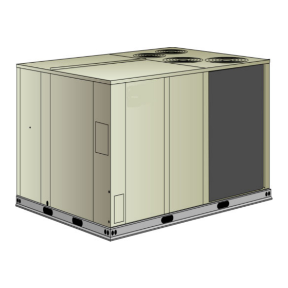
The TCA180S, 180H, 210S, 210H, 240S, 240H and 300S
are available in one cabinet size with cooling capacities from
180,000 to 286,000 Btuh (45.7 to 83.8 kW).
Optional electric heat is field−installed in TCA units. Electric
heat operates in single or multiple stages depending on the
kW input size. 15kW to 60 kW heat sections are available for
the TCA180S, 180H and 15 kW to 90 kW heat sections are
available for the TCA210S, 240S, 210H, 240H and 300S.
TCA180, 210S and 240S units utilize three compressors
and TCA210H, 240H and 300S units utilize four.
All units are designed to accept any of several different ener-
gy management thermostat control systems with minimum
field wiring.
Information contained in this manual is intended for
use by qualified service technicians only. All specifica-
tions are subject to change. Procedures outlined in this
manual are presented as a recommendation only and do not
supersede or replace local or state codes.
If the unit must be lifted for service, rig unit by attaching four
cables to the holes located in the unit base rail (two holes at
each corner). Refer to the installation instructions for the prop-
er rigging technique.
WARNING
Improper installation, adjustment, alteration, service
or maintenance can cause property damage, person-
al injury or loss of life. Installation and service must
be performed by a licensed professional installer or
service agency.
WARNING
Electric shock hazard. Can cause injury
or death. Before attempting to perform
any service or maintenance, turn the
electrical power to unit OFF at discon-
nect switch(es). Unit may have multiple
power supplies.
TCA 15 through 25 ton
Electrostatic discharge can affect electronic
components. Take precautions during unit instal-
lation and service to protect the unit's electronic
controls. Precautions will help to avoid control
exposure to electrostatic discharge by putting
the unit, the control and the technician at the
same electrostatic potential. Neutralize electro-
static charge by touching hand and all tools on an
unpainted unit surface before performing any
service procedure.
VIII Diagrams
©2008 Allied Air Enterprises Inc., a Lennox International Inc. Company
Page 1
ROOFTOP UNITS
TCA−180−210−240−300 (10−08)
ELECTROSTATIC DISCHARGE (ESD)
Precautions and Procedures
CAUTION
Table of Contents
. . . . . . . . . . . . . . . . . . . .
. . . . . . . . . . . . . . . . . . . .
. . . . . . . . . .
. . . . .
. . . . . . . . . . .
. . . . . . . . . . . . . . .
. . . . . . . . . . . . . .
. . . . . .
. . . . . . . . . . . . . . . . . . . . .
. . . . . . . . . . . . . . . . . . . .
. . . . . . . .
. . . . . . . . . . . . . . . . .
. . . . . . . . . . . . . . . . .
. . . . . . . . . . . . . . . . . . .
TCA
Page 2
Page 4
Page 10
Page 10
Page 17
Page 19
Page 20
Page 33
Page 33
Page 34
Page 35
Page 35
Page 37
Page 43
Phone: (803) 738−4000
Advertisement
Table of Contents

Related Manuals for Lennox ALLIED Commercial TCA180S2B Standard


Summary of Contents for Lennox ALLIED Commercial TCA180S2B Standard
-
Page 1: Table Of Contents
Page 37 VIII Diagrams ....Page 43 ©2008 Allied Air Enterprises Inc., a Lennox International Inc. Company Page 1 Phone: (803) 738−4000... -
Page 2: Specifations
SPECIFICATIONS 15 − 17.5 TON General Nominal Tonnage 15 Ton 17.5 Ton Data Model No. TCA180S2B TCA180H2B TCA210S2B TCA210H2B Efficiency Type Standard High Standard High Cooling Gross Cooling Capacity − Btuh (kW) 186,000 (54.5) 186,000 (54.5) 218,000 (63.8) 219,000 (64.1) Performance Net Cooling Capacity −... - Page 3 SPECIFICATIONS 20 − 25 TON General Nominal Tonnage 20 Ton 25 Ton Data Model No. TCA240S2B TCA240H2B TCA300S2B Efficiency Type Standard High Standard Cooling Gross Cooling Capacity − Btuh 243,000 (71.2) 251,000 (73.5) 302,000 (88.4) (kW) Performance Net Cooling Capacity − Btuh (kW) 234,000 (68.5) 240,000 (70.3) 286,000 (83.7)
-
Page 4: Blower Data
BLOWER DATA 15 TON BLOWER TABLE INCLUDES RESISTANCE FOR BASE UNIT WITH WET INDOOR COIL & AIR FILTERS IN PLACE. FOR ALL UNITS ADD: 1 − Any factory installed options air resistance (electric heat, economizer, etc.). See table below 2 − Any field installed accessories air resistance (duct resistance, diffuser, etc.). See page 17 Then determine from table the blower motor output and drive required. - Page 5 BLOWER DATA 17.5 TON BLOWER TABLE INCLUDES RESISTANCE FOR BASE UNIT WITH WET INDOOR COIL & AIR FILTERS IN PLACE. FOR ALL UNITS ADD: 1 − Any factory installed options air resistance (electric heat, economizer, etc.). See table below 2 − Any field installed accessories air resistance (duct resistance, diffuser, etc.). See page 17 Then determine from table the blower motor output and drive required.
- Page 6 BLOWER DATA 20 TON BLOWER TABLE INCLUDES RESISTANCE FOR BASE UNIT WITH WET INDOOR COIL & AIR FILTERS IN PLACE. FOR ALL UNITS ADD: 1 − Any factory installed options air resistance (electric heat, economizer, etc.). See table below 2 − Any field installed accessories air resistance (duct resistance, diffuser, etc.). See page 17 Then determine from table the blower motor output and drive required.
- Page 7 BLOWER DATA 25 TON BLOWER TABLE INCLUDES RESISTANCE FOR BASE UNIT WITH WET INDOOR COIL & AIR FILTERS IN PLACE. FOR ALL UNITS ADD: 1 − Any factory installed options air resistance (electric heat, economizer, etc.). See table below 2 − Any field installed accessories air resistance (duct resistance, diffuser, etc.). See page 17 Then determine from table the blower motor output and drive required.
- Page 8 BLOWER DATA CEILING DIFFUSER AIR RESISTANCE Step-Down Diffuser Flush Diffuser RTD11−185 RTD11−275 Air Volume FD11−185 FD11−275 1 Side/2 All Ends & 1 Side/2 All Ends & 2 Ends Open Sides Open 2 Ends Open Ends Open Ends Open Sides Open w.g.
- Page 9 BLOWER DATA CEILING DIFFUSER AIR THROW DATA Effective Throw Range Effective Throw Range Air Volume Air Volume Model Model Step-Down Flush Step-Down Flush Diffuser Mod- Diffuser Model RTD11−275 FD11−275 RTD11−185 FD11−185 7200 3400 33 − 38 10 − 12 26 − 35 8 −...
-
Page 10: Electric Heat Capacities
ELECTRIC HEAT CAPACITIES 15 kW 30 kW 45 kW 60 kW 90 kW Volts Btuh Btuh Btuh Btuh Btuh Input Input Output Input Output Input Output Input Output Input Output Steps Steps Steps Steps Steps 11.3 38,600 22.5 76,800 33.8 115,300 45.0 153,600... - Page 11 ELECTRICAL/ELECTRIC HEAT DATA TCA180H Voltage − 60hz − 3 phase 208/230V 460V 575V Compressors Rated Load Amps each (total) 15.4 (46.2) 7.4 (22.2) 5.9 (17.7) Locked Rotor Amps each (total) 124 (372) 59.6 (178.8) 49.4 (148.2) Outdoor Fan Full Load Amps each (total) 2.4 (9.6) 1.3 (5.2) 1.0 (4.0)
- Page 12 ELECTRICAL/ELECTRIC HEAT DATA TCA210S Voltage − 60hz − 3 phase 208/230V 460V 575V Compressors Rated Load Amps each (total) 20.2 (60.6) 9.7 (29.1) 8 (24) Locked Rotor Amps each (total) 156 (468) 75 (225) 54 (162) Full Load Amps each (total) 3 (12) 1.5 (6) 1.2 (4.8)
- Page 13 ELECTRICAL/ELECTRIC HEAT DATA TCA210H Voltage − 60hz − 3 phase 208/230V 460V 575V Compressors Rated Load Amps each (to- 14.7 (58.8) 7.1 (28.4) 5.1 (20.4) tal) Locked Rotor Amps each (to- 91 (364) 50 (200) 37 (148) tal) Full Load Amps each (total) 2.4 (9.6) 1.3 (5.2) 1.0 (4.0)
- Page 14 ELECTRICAL/ELECTRIC HEAT DATA TCA240S Voltage − 60hz − 3 phase 208/230V 460V 575V Compressors Rated Load Amps each (total) 22.4 (67.2) 10.9 (32.7) 8.3 (24.9) Locked Rotor Amps each (total) 164 (492) 100 (300) 78 (234) Outdoor Fan Full Load Amps each (total) 2.4 (9.6) 1.3 (5.2) 1 (4)
- Page 15 ELECTRICAL/ELECTRIC HEAT DATA TCA240H Voltage − 60hz − 3 phase 208/230V 460V 575V Compressors Rated Load Amps each (total) 17.3 (69.2) 9 (36) 7.1 (28.4) Locked Rotor Amps each (total) 123 (492) 62 (248) 50 (200) Outdoor Fan Full Load Amps each (total) 2.4 (9.6) 1.3 (5.2) 1 (4)
- Page 16 ELECTRICAL/ELECTRIC HEAT DATA TCA300 Voltage − 60hz − 3 phase 208/230V 460V 575V Compressors Rated Load Amps each (total) 18.6 (74.4) 9.6 (38.4) 7.8 (31.2) Locked Rotor Amps each (total) 156 (624) 75 (300) 54 (216) Outdoor Fan Full Load Amps each (total) 3 (12) 1.5 (6) 1.2 (4.8)
-
Page 17: Options / Accessories
OPTIONS / ACCESSORIES Item 300S COOLING SYSTEM Compressor Crankcase 208/230V − T1CCHT01CD1Y Heater 460V − T1CCHT01CD1G 575V − T1CCHT01CD1J Condensate Drain Trap PVC − LTACDKP09/36 Copper − LTACDKC09/36 Corrosion Protection Efficiency Standard High High Pressure Switch T1SNSR11C−1 Low Ambient Kit T1SNSR12C−1 ELECTRIC HEAT 15 kW... - Page 18 OPTIONS / ACCESSORIES Item 300S Indoor Air Quality (Co ) Sensors Sensor Duct Mounting Kit LTIAQSDMK03/36 Sensor − white case CO display LTAIAQSWDK03/36 Sensor − white case no display LTAIAQSWN03/36 Sensor − black case CO display LTAIAQSND03/36 Sensor − black case, no display LTAIAQSDMBN03/36 Aspiration Box for duct mounting LTIAQABD03/36...
-
Page 19: Parts Arrangment
TCA180/300 PARTS ARRANGEMENT INDOOR COIL FILTERS (SIX − 24 X 24 X 2") ECONOMIZER DAMPERS OUTDOOR (OPTIONAL) FANS BLOWERS FILTER DRIERS BLOWER MOTOR OUTDOOR CONDENSATE COIL DRAIN COMPRESSORS − (4TH COMPRESSOR MCC (A45) ON 210H, 240H, & CONTROL 300H UNITS ONLY) ELECTRIC HEAT (OPTIONAL) FIGURE 1... -
Page 20: I Unit Components
I−UNIT COMPONENTS 5−Terminal Strip TB1 All indoor thermostat connections will be to TB1 located on TCA unit components are shown in figure 1. All units come MCC board A45. For thermostats with occupied and un- standard with removeable unit panels. All L1, L2, and L3 wir- occupied"... - Page 21 12−Blower Motor Overload Relay S42 14−MCC Control A45 S42 is a manual reset overload relay, used in all TCA units The main control module A45 (figure 6) controls all cool- equipped with 10 or more HP standard efficiency motors. ing operation and serves as a staging point for all internal The relay is connected in line with the blower motor to mon- inputs to the appropriate components of the TCA unit.
- Page 22 TABLE 1 UNIT TYPE DIP SWITCH (FACTORY−SET) Indicates Action Status No power to Check field wiring. board. Press MCC pushbutton and Processor error. hold for three seconds to reset TGA UNITS processor.* TCA UNITS Flashes Normal. None. Slowly Flashes Invalid unit DIP Make sure switches are set Rapidly switch selected.
- Page 23 TABLE 2 TABLE 5 TB1 TERMINAL DESIGNATIONS P113 TERMINAL DESIGNATIONS Cool Stage 1 Terminal Function Cool Stage 2 Relay KA To Freeze Stat Cool Stage 3 (N/A) From Freeze Stat Cool Stage 4 (N/A) Relay KA To Outdoor Fan Relay Freeze Stat to Compressor Contactor Heat Stage 1 Relay KB To Freeze Stat...
- Page 24 B−Cooling Components 3−Low Ambient Switches (optional) S11, S84 & S85 (all units) All units use independent cooling circuits consisting of sepa- rate compressors, condenser coils and evaporator coils. S94 (210H, 240H, 300S only) See figures 7 and 8. Four draw−through type condenser fans The low ambient switch is an optional field installed auto- are used in TCA180/300 units.
- Page 25 TCA180H, 180S, 210S & 240S PLUMBING, COMPRESSOR FREEZESTAT (3) AND REFRIGERANT CIRCUITS DETAIL ONE FOR EACH STAGE OF COIL (LOCATED ON RETURN BEND) DRIERS (B2) (B1) (B13) (S7) optional (S28) optional COMPRESSOR (B1) DISCHARGE LINE PRESSURE TAP SUCTION LINE PRESSURE TAP OPTIONAL HIGH PRESSURE SWITCH...
- Page 26 TCA210H, 240H, 300S PLUMBING, COMPRESSOR FREEZESTAT (4) AND REFRIGERANT CIRCUITS DETAIL ONE FOR EACH STAGE OF COIL (LOCATED ON RETURN BEND) (B2) DRIERS (B13) (B1) (B20) *(S7) *(S28) *(S96) *optional switches COMPRESSOR (B1) DISCHARGE LINE SUCTION LINE PRESSURE TAP PRESSURE TAP OPTIONAL HIGH PRESSURE SWITCH...
- Page 27 C−Blower Compartment Determining Unit Air Volume The blower compartment in TCA180/300 units is located 1− The following measurements must be made with a dry in- between the evaporator coil and the compressor / control sec- door coil. Run blower without cooling demand. Air filters tion on the opposite side of the condenser coil.
- Page 28 A force below these values indicates an underten- Check Belt Tension sioned belt. A force above these values indicates an Overtensioning belts shortens belt and bearing life. Check overtensioned belt. belt tension as follows: MEASURE BELT TENSION 1− Measure span length X. See figure 10. 2−...
- Page 29 D−Optional Electric Heat Components ELECTRIC HEAT HAT SECTION See ELECTRICAL / ELECTRIC HEAT (table of contents) for possible TCA to EHA matchups and electrical ratings. CONTROL BOX All electric heat sections consist of electric heating ele- ments exposed directly to the airstream. See figure 1. Two electric heat sections (first section and second sec- tion) are used in all 15kW through 90kW heaters used in TCA180/300 units.
- Page 30 6−Time Delay DL5 11−High Temperature Limits S15 and S107 Time delay DL5 is identical to DL2. DL5 further staggers (Primary) the (W2) second stage heating elements by providing a S15 and S107 are SPST N.C. auto-reset thermostats located timed interval between the energizing of the elements on the back panel of the electric heat section below the heating activated by DL2 and elements activated by DL5.
- Page 31 EHA 15, 30, 45, 60, and 90 KW ELECTRIC HEAT SECTION PARTS ARRANGEMENT HEATING ELEMENTS HE1 − HE14 ELECTRIC HEAT VESTIBULE CONTROL WIRE HARNESS PRIMARY ELECTRIC HEAT LIMIT S15(1 SECTION) S107(2 SECTION) FIGURE 14 TABLE 8 TCA180/300 ELECTRIC HEAT SECTION FUSE RATING FUSE (3 each) EHA QUANTITY VOLTAGES...
- Page 32 TCA180/300 ELECTRIC HEAT VESTIBULE PARTS ARRANGEMENT TERMINAL STRIP FIRST HEAT SECTION (LEFT SIDE) (TB3) FUSE F3 FIRST STAGE ELECTRIC SECOND STAGE ELECTRIC FUSE F3 FUSE F3 FUSE F3 F3 - 1 HEAT CONTACTOR K15 HEAT CONTACTOR K16 F3 - 4 F3 - 2 F3 - 3 TERMINAL STRIP...
-
Page 33: Placement And Installation
II−PLACEMENT AND INSTALLATION 210H, 240H, 300S − Units contain four refrigerant circuits or systems. Evap- Make sure the unit is installed in accordance with the orator and condenser coil refrigerant circuit 1 makes installation instructions and all applicable codes. See up stage 1 cooling. -
Page 34: Charging
5− 180S & H, 210S, 240S,− 4− Apply the outdoor temperature to tables 9 through 15 to determine normal operating pressures. First−stage thermostat demand will energize condens- er fans 1 and 2. Second−stage thermostat demand will 5− Compare the normal operating pressures to the pres- energize condenser fans 3 and 4. -
Page 35: System Service Checks
Charge Verification − Approach Method TABLE 12 1− Using the same thermometer, compare liquid temper- TCA210H NORMAL OPERATING PRESSURES ature to outdoor ambient temperature. CIRCUIT 1 CIRCUIT 2 CIRCUIT 3 CIRCUIT 4 Outdoor Coil Dis. Suc. Dis. Suc. Dis. Dis. Suc. - Page 36 B−Lubrication WARNING All motors used in TCA units are factory lubricated, no further lubrication is required. Product contains fiberglass wool. Disturbing the insulation in this product during Blower shaft bearings are prelubricated. For extended installation, maintenance, or repair will expose you bearing life, relubricate at least once every two years with a to fiberglass wool.
-
Page 37: Accessories
VII−ACCESSORIES TYPICAL FLASHING DETAIL The accessories section describes the application of most of UNIT BASE the optional accessories which can be installed to the TGA BOTTOM units. UNIT BASE A−LARMF and LARMFH Mounting Frames RAIL When installing either the TCA units on a combustible surface for downflow discharge applications, the LARMF18/36 14-inch FIBERGLASS INSULATION... - Page 38 Optional Sensors A6 ENTHALPY CONTROLLER An optional differential sensor (A62) may be used with the A7 outdoor sensor to compare outdoor air enthalpy to re- DAMPER MINI- turn air enthalpy. When the outdoor air enthalpy is below MUM POSITION the return air enthalpy, outdoor air is used for free cooling. A mixed air sensor (R1) is used in modulating the dampers IAQ MAXIMUM to 55...
- Page 39 1− Set thermostat to occupied mode if the feature is avail- Economizer Operation able. Make sure jumper is in place between A45 con- trol board TB1 terminals A1 and A2 if using a thermo- The occupied time period is determined by the thermostat stat which does not have the feature.
- Page 40 Optional manual and motorized outdoor air dampers pro- MANUAL OUTDOOR AIR DAMPER vide fresh outdoor air. Follow the steps to determine fresh air percentage 1− Measure outdoor air temperature. Mark the point on the bottom line of chart 1 and label the point A" (40_F, 4_C shown).
- Page 41 CHART 1 CALCULATE MINIMUM FRESH AIR PERCENTAGE MIXED AND RETURN AIR TEMPERATURE −20 −10 −29 −23 −18 −12 −7 −1 −20 −10 −29 −23 −18 −12 −7 −1 OUTDOOR AIR TEMPERATURE TABLE 18 ECONOMIZER OPERATION−OUTDOOR AIR IS NOT SUITABLE FOR FREE COOLING −− FREE COOL LED OFF" Á...
- Page 42 E−LAGED(H) Gravity Exhaust Dampers F−C1PWRE20C Power Exhaust Fans LAGED18/24 dampers (figure available C1PWRE20C available for TCA180/300 units are power ex- TCA180/300 units, used downflow haust fans used in downflow applications only. The fans re- LAGED(H)18/24 are used in horizontal air discharge ap- quire optional down-flow gravity exhaust dampers and plications.
- Page 43 VIII−Wiring Diagrams and Sequence of Operation TCA180S, 180H 210S, 240S UNIT DIAGRAM Page 43...
- Page 44 TCA180S, 180H, 210S, 240S SEQUENCE OF OPERATION Power: 1. Line voltage from unit disconnect S48 or TB2 if equipped, energizes transformer T1. T1 provides 24VAC to the unit cooling, heating and blower controls and TB1 and TB14. Blower Operation: 2. The main control module receives a demand from thermostat terminal G. A45 energizes blower contactor K3 with 24VAC.
- Page 45 TCA210H, 240H, 300S UNIT DIAGRAM Page 45...
- Page 46 TCA210H, 240H, 300S SEQUENCE OF OPERATION Power: 1. Line voltage from unit disconnect S48 or TB2 if equipped, energizes transformer T1. T1 provides 24VAC to the unit cooling, heating and blower controls and TB1 and TB14. Blower Operation: 2. The main control module receives a demand from thermostat terminal G. A45 energizes blower contactor K3 with 24VAC.
- Page 47 EHA−15, 30, 45, 60, 90kW Y VOLTAGE Page 47...
- Page 48 EHA−15, 30, 45, 60, 90KW − G, J, M Page 48...
- Page 49 Sequence of Operation −EHA15, 30, 45, 60, 90kW − Y and G, J, M NOTE: This sequence of operation is for all Electric END OF SECOND STAGE HEAT: Heat kW ratings Y, G, J and M voltages. Heating demand is satisfied. Terminal W2 in the ther- mostat is de−energized.
- Page 50 ELECTRONIC OR ELECTROMECHANICAL THERMOSTAT POWER: Terminal strip TB1 found on the main control module A45 energize thermostat components with 24VAC. OPERATION: The main control module A45 receives data from the electronic thermostat A2 (Y1, Y2, Y3, W1, W2, G, OCP) A45 energizes the appropriate components for heat or cool demand.
- Page 51 T" SERIES ECONOMIZER SEQUENCE OF OPERATION POWER: Economizer control module A6 is energized through main module A45, P142 when contactor K3 is ener- gized. OPERATION: Enthalpy sensor A7 and A62 (if differential enthalpy is used) communicates to the economizer control module A6 when to power the damper motor B7.