
Related Manuals for Lennox @DNOVA THND 045


Summary of Contents for Lennox @DNOVA THND 045
- Page 1 INSTALLATION, OPERATING AND MAINTENANCE WALL MOUNTED PACKAGED INDOOR UNIT @DNOVA 2,5 - 38 kW ADNOVA-THN_R410A- IOM-1506-E www.lennoxemea.com...
-
Page 3: Table Of Contents
1 General Description 1.1 Structure 1.2 Field of application 1.3 Cooling circuit 1.4 Installation warnings 2 Inspection / Transport / Positioning 2.1 Inspection on receipt 2.2 Lifting and Transport 2.3 Unpacking 2.4 Positioning 3 Installation 4 Evacuation and Charging Operations 4.1 Introduction 4.2 Vacuum and charging machine 4.3 Evacuating a circuit “contaminated”... -
Page 4: General Description
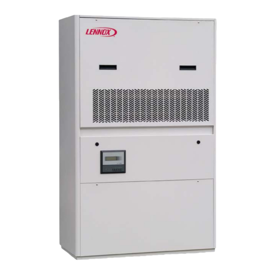
General Description THND/U “Lennox Telecom units” are air conditioners for low- and medium-powered telephone exchanges. They are designed to be mounted inside shelter. THND/U air conditioners are direct expansion package units with an air-cooled condenser system. They are distinguished by an innovative air circulation system which significantly enhances performance in all conditions. -
Page 5: Cooling Circuit
Cooling circuit The entire cooling circuit is built in the Lennox factory using only components of the finest quality brands and processes conforming to the specifications of Directive 97/23 for brazing and testing. Compressors: only scroll-type compressors of leading international manufacturers are used in the THND/U/X units. -
Page 6: Installation Warnings
Fig. 1 Basic cooling circuit Compressor Condenser Thermostatic valve Evaporator Filter dryer Sight glass Low pressure switch High pressure switch Condensing pressure probe Installation warnings General rules • When installing or servicing the unit, you must strictly follow the rules provided in this manual, comply with the directions on the units themselves and take all such precautions as are necessary. -
Page 7: Inspection / Transport / Positioning
Delivery Slip before signing it. Lennox or its Agent must be promptly notified of the entity of the damage. The Customer must submit a written report describing every significant sign of damage. - Page 8 Fig. 2 THND/X 045...170 (rear view) @DNOVA THN_R410A-IOM-1506-E - 6 -...
- Page 9 THND/X180-200 (rear view) THNU220-250 (rear view) @DNOVA THN_R410A-IOM-1506-E - 7 -...
- Page 10 THNU090..120 (rear view) THNU045..073 – 150-170 @DNOVA THN_R410A-IOM-1506-E - 8 -...
- Page 11 THNU180-200 THNU220-250 @DNOVA THN_R410A-IOM-1506-E - 9 -...
-
Page 12: Installation
Installation The THND/U/X package air-conditioning unit is suitable for all environments except aggressive ones. Do not place any obstacles near the units and make sure that the air flow is not impeded by obstacles and/or situations causing back suction. The following steps should be carried out to ensure proper installation •... -
Page 13: Evacuation And Charging Operations
Evacuation and Charging Operations This type of work must be carried out by qualified personnel only trained to do their job in accordance with current laws and regulations. Introduction The simultaneous presence of liquid and vapor makes it necessary for both to be in a state of saturation (Gibbs law), as shown in Fig. -
Page 14: Vacuum And Charging Machine
Vacuum and charging machine Vacuum cycle In general it is preferable to apply a “long” rather than “hard” vacuum: reaching low pressures too abruptly may in fact cause any trapped humidity to evaporate instantaneously, thereby freezing part of it. Fig. 4 Vacuum cycle diagram The Fig. -
Page 15: Charging Positions (Single Point)
Charging positions (single point) The best position for charging the air conditioners is the section between the thermostatic valve and the evaporator; care should be taken to avoid fixing the thermostat bulb until the operation is complete: this is important to ensure that the valve orifice remains open so as to allow the passage of refrigerant also toward the condenser/receiver. -
Page 16: Starting Up
Starting Up Preliminary checks • Check that the electrical connections have been made properly and that all the terminals are securely tightened. This check should also be included in a periodic six-month inspection. • Check that the voltage at the RST terminals is 400 V ± 5%and make sure the yellow indicator light of the phase sequence relay is on. -
Page 17: Starting Up Instructions
Starting up instructions Electric connections and starting up • Open electrical panel. • Disconnect the main switch. • Inlet cables holes are positioned on the bottom side of the unit • Connect the power supply and the earth connection to the main switch and to the main earth connection. •... - Page 18 Checking the refrigerant level • After a few hours of operation, check whether the liquid level indicator has a green ring: a yellow color indicates the presence of humidity in the circuit. In such a case the circuit must be dehumidified by qualified personnel.
-
Page 19: Setting Operating Parameters
Setting Operating Parameters Generalities All the control devices are set and tested in the factory before the unit is dispatched. However, after the unit has been in service for a reasonable period of time you can perform a check on the operating and safety devices. -
Page 20: Maintenance
Maintenance The only operations to be performed by the user are to switch the unit On and Off. All other operations are to be considered maintenance work and must thus be carried out by qualified personnel trained to do their job in accordance with current laws and regulations. -
Page 21: Inspecting The Air Filter
Inspecting the air filter 1. Remove the panel above the condenser fan to access the damper and air filter compartment. 2. Pull out the air filter. 3. Check the condition of the filter and replace it if necessary Inspecting the damper servomotor 1. -
Page 22: Repairing The Cooling Circuit
Repairing the cooling circuit Warning: while performing repairs on the cooling circuit or maintenance work on the compressors, make sure the circuit is left open for as little time as possible. Even if briefly exposed to air, ester oils tend to absorb large amounts of humidity, which results in the formation of weak acids. -
Page 23: Recharging With Refrigerant R410A
Introduce refrigerant through the inlet in the liquid line. A unit that was originally charged with R410A in the factory must not be charged with other refrigerants without the written authorization of Lennox. Environmental protection The law implementing the regulations (reg. EEC 2037/00) which govern the use of ozone---depleting... -
Page 24: Troubleshooting
Troubleshooting On the next pages you will find a list of the most common causes that may cause the package unit to fail or malfunction. These causes are broken down according to easily identifiable symptoms. You should be extremely careful when attempting to implement any of the possible remedies suggested: overconfidence can result in injuries, even serious ones, to inexpert individuals. - Page 26 LENNOX DISTRIBUTION +33 4 72 23 20 20 +33 4 72 23 20 20 Due to LENNOX EMEA ongoing commitment to quality, the specifi cations, ratings and dimensions are subject to change without notice and without incurring liability. ADNOVA-THN_R410A- Improper installation, adjustment, alteration, service or maintenance can cause property damage or personal injury.