Table of Contents
Advertisement
Quick Links
E2008 Lennox Industries Inc.
Dallas, Texas, USA
RETAIN THESE INSTRUCTIONS
FOR FUTURE REFERENCE
WARNING
Improper
installation,
service or maintenance can cause personal injury,
loss of life, or damage to property.
Installation and service must be performed by a
licensed professional installer (or equivalent) or a
service agency.
CAUTION
Physical contact with metal edges and corners
while applying excessive force or rapid motion can
result in personal injury. Be aware of, and use
caution when working near these areas during
installation or while servicing this equipment.
IMPORTANT
The Clean Air Act of 1990 bans the intentional
venting of refrigerant (CFCs, HCFCs and HFCs) as
of July 1, 1992. Approved methods of recovery,
recycling or reclaiming must be followed. Fines
and/or
incarceration
noncompliance.
IMPORTANT
This unit must be matched with an indoor coil as
specified in the Lennox Engineering Handbook.
Coils previously charged with HCFC−22 must be
flushed.
03/08
*2P0308*
adjustment,
alteration,
may
be
levied
for
INSTALLATION
INSTRUCTIONS
T−Classt TSA*H4 Units
TSA036H4N41, TSA042H4N41,
TSA048H4N41 and TSA060H4N41
AIR CONDITIONER
506083−01
03/08
Table of Contents
. . . . . . . . . . . . . . . . . . . . . . . . . . . . . . . . .
. . . . . . . . . . . . . . . . . . . . . . . . . . . . . . . . . . .
Shipping and Packing List
Check the unit for shipping damage and that all included
items listed below are intact. If damaged, or if parts are
missing, immediately contact the last carrier.
1
Assembled outdoor unit
1
Liquid line filter drier
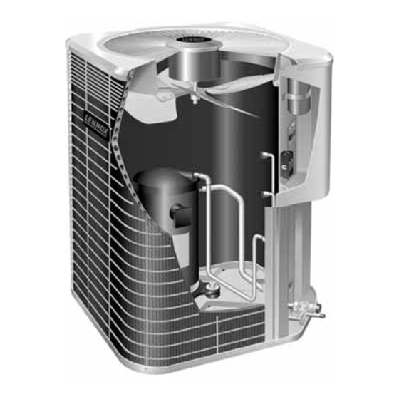
TSA*H4 Air Conditioners
The TSA*H4 Air Conditioners, which will also be referred to
in this instruction as the outdoor unit, uses HFC−410A
refrigerant. This outdoor unit must be installed with a
matching indoor unit and line set as outlined in the TSA*H4
Engineering Handbook. TSA*H4 Air Conditioners are
designed for use in thermal expansion valve (TXV)
systems.
Page 1
. . . . . . . . . . . . . . . . . . . . . . . .
. . . . . . . . . . . . . . . . . . . . . . . . .
. . . . . . . . . . . . . . . . . . . . . . . . . . . . .
. . . . . . . . . . . . . . . . .
. . . . . . . . . . . . . . . . . . . . .
. . . . . . . . . . . . . . . . . . . . .
. . . . . . . . . . . . . . . . . . . . . . . . . . . . .
. . . . . . . . . . . .
. . . . . . . . . . . . . . . . . . . . . . . . . . . . .
. . . . . . . . . . . . . . . . . . . . . . . . . . . . . . .
. . . . . . . . . . . . . . . . . . . . . . . . . .
. . . . . . . . . . .
. . . . . . . . . . . . . . . . . . . . . . . . . .
. . . . . . . . . . . . . . . .
. . . . . . . . . . . . . . . . . . . . . . . . . . . . . .
. . . . . . . . . . . . . . . . . . . . . . . . .
. . . . . . . . . . . . . .
506083−01
*P506083-01*
Litho U.S.A.
1
1
2
2
. . . . . . .
4
5
5
6
7
8
9
. . . . . . . . .
10
12
12
13
13
15
18
19
19
20
Advertisement
Table of Contents

Related Manuals for Lennox TSA036H4N41


Summary of Contents for Lennox TSA036H4N41
-
Page 1: Table Of Contents
This unit must be matched with an indoor coil as matching indoor unit and line set as outlined in the TSA*H4 specified in the Lennox Engineering Handbook. Engineering Handbook. TSA*H4 Air Conditioners are Coils previously charged with HCFC−22 must be designed for use in thermal expansion valve (TXV) flushed. -
Page 2: Unit Dimensions
OPERATING SERVICE VALVES available from address shown below, or contact your supervisor. IMPORTANT Lennox Industries Inc. P.O. Box 799900 Only use Allen wrenches of sufficient hardness Dallas, TX 75379−9900 (50Rc − Rockwell Harness Scale minimum). Fully insert the wrench into the valve stem recess. - Page 3 OUTDOOR UNIT (Uncased Coil Shown) OUTDOOR COIL HIGH PRESSURE PRESSURE LIQUID LINE SUCTION LINE GAUGE MANIFOLD SERVICE VALVE SERVICE VALVE HFC−410A COMPRESSOR DRUM FILTER DRIER Figure 1. Typical Manifold Gauge Connection Setup Each service valve is equipped with a service port which To Open and Close Angle−Type Service Valve: has a factory−installed valve stem.
-
Page 4: Recovering Refrigerant From Existing System
3. Replace the stem cap and tighten as follows: VALVE IS BACK−SEATED SERVICE PORT CAP (OPENED) With Torque Wrench: Finger tighten and then tighten per table 1. SERVICE PORT SERVICE PORT CORE Without Torque Wrench: Finger tighten and use an OPEN TO BOTH (VALVE STEM SHOWN OPEN) INDOOR AND... -
Page 5: Removing Existing Outdoor Unit
3. When the low side system pressures reach 0 psig, property, not from the installation property. Install the close the suction line valve. unit as far as possible from the property line. 4. Check gauges after shutdown to confirm that the When possible, do not install the unit directly outside valves are not allowing refrigerant to flow back into the a window. -
Page 6: New Or Replacement Line Set
LINE SERVICE VALVE LIQUID LINE from the outdoor unit (braze connections) to the indoor unit FILTER DRIER coil (flare or braze connections). Use Lennox L15 (braze, OUTDOOR non−flare) series line set, or use field−fabricated refrigerant UNIT lines as listed below. -
Page 7: Brazing Connections
IMPORTANT - REFRIGERANT LINES MUST NOT CONTACT WALL. WARNING LIQUID OUTSIDE WALL LINE SUCTION LINE Polyol ester (POE) oils used with HFC−410A WOOD BLOCK refrigerant absorb moisture very quickly. It is very BETWEEN STUDS important that the refrigerant system be kept closed as much as possible. -
Page 8: Removing Indoor Unit Metering Device
REMOVE CAP AND CORE FROM ATTACH CUT AND DEBUR BOTH LIQUID AND SUCTION GAUGES SERVICE PORTS SERVICE PORT MUST BE OPEN TO ALLOW EXIT SERVICE POINT FOR NITROGEN VALVE SUCTION LINE OUTDOOR INDOOR UNIT UNIT LIQUID LINE SERVICE VALVE FLOW NITROGEN WRAP BRAZE LINE SET NITROGEN... -
Page 9: Flushing The System
LIQUID LINE ONLY) ORIFICE HOUSING existing traps. Polyol ester (POE) oils are used in DISTRIBUTOR Lennox units charged with HFC−410A refrigerant. TUBES TEFLON Residual mineral oil can act as an insulator, RING preventing proper heat transfer. It can also clog... -
Page 10: Installing New Indoor Unit Metering Device
5. Close the valve on the inverted HCFC−22 drum and Two gauge sets (one for HCFC−22; one for the gauge set valves. Pump the remaining refrigerant HFC−410A). out of the recovery machine and turn the machine off. 6. Use dry nitrogen to break the vacuum on the INVERTED HCFC−22 CYLINDER CONTAINS CLEAN HCFC−22 TO refrigerant lines and indoor unit coil before removing... - Page 11 TYPICAL TXV INSTALLATION PROCEDURE 6. Attach the sensing bulb of the TXV in the proper orientation as illustrated in figure 22 to the suction line The TXV unit can be installed internal or external to the using the clamp and screws provided. indoor coil.
-
Page 12: Testing For Leaks
6. After a few minutes, open a refrigerant port to ensure Testing for Leaks the refrigerant you added is adequate to be detected. After the line set has been connected to the indoor unit and NOTE − Amounts of refrigerant will vary with line lengths. outdoor unit, check the line set connections and indoor unit 7. -
Page 13: Servicing Unit Delivered Void Of Charge
6. When the absolute pressure reaches 23,000 microns In Canada, wiring must conform with current local codes (29.01 inches of mercury), close the manifold gauge and the current Canadian Electrical Code (CEC). Refer to valves, turn off the vacuum pump and disconnect the the furnace or blower coil installation instructions for manifold gauge center port hose from vacuum pump. - Page 14 5. Install low−voltage wiring from outdoor to indoor unit 6. Do not bundle any excess 24V control wire inside and from thermostat to indoor unit. control box. Run control wire through installed wire tie and tighten wire tie to provided low voltage strain relief INDOOR UNIT THERMOSTAT and to maintain separation of field installed low and...
-
Page 15: Start−Up And Charging Procedures
6. Set the thermostat for a cooling demand. Turn on Start−Up and Charging Procedures power to the indoor indoor unit and close the outdoor unit disconnect switch to start the unit. IMPORTANT 7. Recheck voltage while the unit is running. Power must be within range shown on the nameplate. - Page 16 START: Determine how refrigerant is metered WHEN TO CHARGE? Warm weather best Can charge in colder weather CHARGE METHOD? Determine by: Metering device type OUTDOOR AMBIENT Outdoor ambient temperature TEMPERATURE REQUIREMENTS: Sufficient heat load in structure 65ºF (18.3ºC) 64ºF (17.7ºC) Indoor temperature between 70-80ºF (21−26ºC) and ABOVE and BELOW...
- Page 17 1. Confirm proper airflow across coil using figure 65ºF START: Measure outdoor ambient temperature 2. Compare unit pressures with Table 4, Normal ABOVE Operating Pressures. USE WEIGH-IN METHOD DO NOT CHARGE UNIT 3. Set thermostat to call for heat (must have a ABOVE or Weigh-in or remove refrigerant cooling load between 70-80ºF (21−26ºC)
-
Page 18: System Operation
Table 4. HFC−410A Normal Operating Pressures (Liquid +10 and Suction +5 psig) Use this table to perform maintenance checks; it is not a procedure for charging the system. Minor variations in these pressures may be due to IMPORTANT differences in installations. Significant deviations could mean that the system is not properly charged or that a problem exists with some component in the system. -
Page 19: Maintenance
LOW PRESSURE SWITCH OPTIONAL ACCESSORIES Refer to the Engineering Handbook for optional TSA*H4 units are equipped with a low pressure switch that accessories that may apply to this unit. The following may is located in the suction line to the compressor. The switch or may not apply: is a SPST, auto−reset switch that is normally closed. -
Page 20: Start−Up And Performance Checklist
PUSH PIN PROGRAMMABLE THERMOSTATS MESH Â Â Â Â Â Â Â Â Â Â Â Â Your Lennox system controlled SCREEN Â Â Â Â Â Â Â Â Â Â Â Â programmable thermostat. These thermostats provide the added feature of programmable time-of-day setpoints for Figure 33.