Table of Contents
Advertisement
Quick Links
Advertisement
Table of Contents

Related Manuals for Delta CANopen DVPCOPM-SL


Summary of Contents for Delta CANopen DVPCOPM-SL
- Page 1 DVPCOPM-SL CANopen Communication Module Operation Manual DVP-0204420-02...
-
Page 2: Table Of Contents
Installing DVPCOPM-SL and DVP-SV CPU on DIN Rail ............10 Connecting to CANopen Connection Port................11 Constructing CANopen Network .....................11 How to Construct a CANopen Network ................. 11 Data Mapping in CANopen Network ..................13 How to Configure Network by Delta CANopen Builder Software ..........14 DVP-PLC Operation Manual... - Page 3 CANopen Communication Module DVPCOPM-SL Saving the Configuration Data....................26 CANopen Network Control ....................26 Sending SDO, NMT and Reading Emergency by Ladder Diagram ..........28 Principle ..........................28 Structure of SDO Request Message..................28 Structure of NMT Service Message ..................30 Structure of Emergency Request Message ................
-
Page 4: Introduction
CANopen Communication Module DVPCOPM-SL Introduction 1. To ensure correct installation and operation of DVPCOPM-SL, please read this chapter carefully before using your DVPCOPM-SL. 2. This chapter only provides introductory information on DVPCOPM-SL. For more detailed information on CANopen protocol, please refer to relevant references or literatures. 3. -
Page 5: Functions
Able to read Emergency message through the ladder diagram in PLC. SYNC producer; Range: 0 ~ 65,535ms. As the interface between Delta CANopen Builder software and CANopen network. The software can configure the network directly through DVPCOPM-SL. In the auto data exchange with PLC, the user only has to program the D register mapped in PLC without applying FROM/TO instructions. -
Page 6: Explanation Of Output/Input Mapping Area Of Dvpcopm-Sl
CANopen Communication Module DVPCOPM-SL Storage -25ºC ~ 70ºC (temperature); 5 ~ 95% (humidity) Shock/vibration International standard: IEC 61131-2, IEC 68-2-6 (TEST Fc)/IEC 61131-2 & IEC immunity 68-2-27 (TEST Ea) Certificates IEC 61131-2, UL508 1.3 Explanation of Output/Input Mapping Area of DVPCOPM-SL When DVPCOPM-SL serves as the master of the CANopen network, the output/ input mapping areas in different positions of the left side of PLC are shown as below table is. -
Page 7: Product Profile & Outline
CANopen Communication Module DVPCOPM-SL When DVPCOPM-SL serves as the slave of CANopen network, the input and output mapping areas in the different positions of the left side of PLC are shown in below table. Of the left side of PLC (except DVP10MC11T), the position where the first DVPCOPM-SL is equipped is 1; the position where the second one is equipped is 2;... -
Page 8: Product Profiles
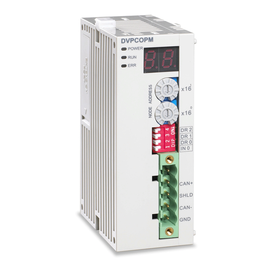
CANopen Communication Module DVPCOPM-SL 2.2 Product Profiles DVPCOPM-SL PO WER DR 2 DR 1 DR 0 IN 0 SHLD CAN- 1. Model name 6. Fixing clip for I/O module 2. I/O module Interface 7. Address switch 3. POWER, RUN, ERR indicators 8. -
Page 9: Can Network Endpoint And Topology Structure
CANopen Communication Module DVPCOPM-SL 2.4 CAN Network Endpoint and Topology Structure In order to make the CAN communication more stable, the two endpoints of the CAN network are connected to 120 ohm terminal resistors. The topology structure of the CAN network is illustrated below. 2.5 Address Switch The switch is used on setting up the node address of DVPCOPM-SL on CANopen network. -
Page 10: Function Switch
CANopen Communication Module DVPCOPM-SL 2.6 Function Switch The switch is used on setting up the baud rate between DVPCOPM-SL and CANopen network (DR0 ~ DR2). See the table below for the baud rate and its maximum communication distance. Baud rate (bps) Max. -
Page 11: Basic Operation
CANopen Communication Module DVPCOPM-SL Basic Operation 3.1 Connecting DVPCOPM-SL to DVP-SV CPU Open the fixing clip on top and bottom of DVP-SV. Meet the extension port of DVPCOPM-SL with DVP-SV, as Press the fixing clips on top and bottom of DVP-SV and check is the connection is fine, as DVPCOPM DVP28SV POWE R... -
Page 12: Connecting To Canopen Connection Port
In the example below, we will illustrate how to control RUN/STOP and speed of a Delta ASD-B servo drive by a Delta digital I/O module DVP-08ST. - Page 13 CANopen Communication Module DVPCOPM-SL Set up DVPCOPM-SL and IFD9503 according to the table below. For how to operate IFD9503, please refer to Chapter 13. Module Node address Baud rate (bps) DVPCOPM-SL IFD9503 02 (connected to ASD-B) IFD9503 03 (connected to DVP-12SA) Set up ASD-B as follows: Parameter Set value...
-
Page 14: Data Mapping In Canopen Network
CANopen Communication Module DVPCOPM-SL 4.2 Data Mapping in CANopen Network Data mapping in DVP-12SA DVP-08ST, connected on the right hand side of DVP-12SA, offers 8 channels of digital input and 1 byte of input data. In this example, we will use X0 and X1 on DVP-08ST to RUN/STOP ASD-B and select speed. Y0 is for the output signal of ASD-B operational status. -
Page 15: How To Configure Network By Delta Canopen Builder Software
Input data D6036 Multi-function digital output Output data D6286 Multi-function digital input 4.3 How to Configure Network by Delta CANopen Builder Software Using CANopen Builder to scan the network (1) Open CANopen Builder software, as below: DVP-PLC Operation Manual... - Page 16 CANopen Communication Module DVPCOPM-SL (2) Select ”Setup” => ”Communication Setting” => ”System Channel”, and the "Serial Port Setting” dialog box will appear. (3) Set up the communication parameters in the PC and DVP-SV, e.g. the communication port, address, baud rate and communication format.
- Page 17 CANopen Communication Module DVPCOPM-SL (4) Select “Network” => ”Online”, and the “Select Communication Channel” dialog box will appear. In this example, if the connection with DVP-SV is in normal status, you will see the screen as below. If there are more than one DVPCOPM-SL module (less than 8) connected to the left side of DVP-SV and supposed there are two connected in this example, after clicking on “Online”, you will see the screen as below.
- Page 18 CANopen Communication Module DVPCOPM-SL (5) Select the DVPCOPM-SL which needs to establish the communication. Click on “OK” and start to scan all the slaves in the network. If the network installation and power supply are normal, you will see the screen as below.
- Page 19 CANopen Communication Module DVPCOPM-SL Setting up parameters in CANopen master Select “Network” => ”Master Parameter”, and you will see the dialog box as below. Work Mode: The work mode of DVPCOPM-SL. You can select either “Master Mode” or “Slave Mode”. Cycle Period: The period of sending synchronous information.
- Page 20 CANopen Communication Module DVPCOPM-SL (2) Relevant parameter settings Error Control Protocol: In the “Node Configuration…” page, click on “Error Control Protocol”, and you will see the dialog box appearing as below. In this page, you can set up parameters for error control, e.g. “Master Consumer Timeout” and “Node Heartbeat Producer Time”.
- Page 21 CANopen Communication Module DVPCOPM-SL Parameter Name Explanation Remark Node Slave sends the heartbeat message to heartbeat master in cycle of “Node heartbeat The time for “Master consumer producer time producer time” timeout” should be longer than Heartbeat If master does not receive the heartbeat that for “slave heartbeat Master message from slave within the period of...
- Page 22 CANopen Communication Module DVPCOPM-SL Auto SDO Configuration: In the “Node Configuration” page, click on “Auto SDO Configuration”, and you will see the page as below. Click on “Add” to edit Auto SDO. Click on “Edit” to modify the Auto SDO selected. Please note that the Auto SDO cannot be longer than 8 bytes, and every slave is able to posses maximum 20 auto SDOs.
- Page 23 CANopen Communication Module DVPCOPM-SL PDO mapping: In the “Node Configuration…” page, select a TxPDO or RxPDO in “Configured PDO” and click on “PDO Mapping”, and you will enter the “PDO Mapping…” page as below. You can add the parameters in “Available Objects from EDS file”...
- Page 24 CANopen Communication Module DVPCOPM-SL PDO COB-ID setting rule is as follows. RxPDO Number COB-ID(HEX) TxPDO Number COB-ID (HEX) RxPDO1 200+slave node address TxPDO1 180+slave node address RxPDO2 300+slave node address TxPDO2 280+slave node address RxPDO3 400+slave node address TxPDO3 380+slave node address RxPDO4 500+slave node address TxPDO4...
- Page 25 CANopen Communication Module DVPCOPM-SL Transmission Type Description Remark RxPDO To analogize on basis of transmission type 1 and 2 3~240 SYNCH Cycle TxPDO To analogize on basis of transmission type 1 and 2 When there is any change for RxPDO, RxPDO data is transmitted to slave and the PxPDO that slave receives is RxPDO valid immediately.
- Page 26 CANopen Communication Module DVPCOPM-SL > (2) In this example, first select DVP-SS/SA/EH PLC at Node 003 and click on to add this node into the node list. After this, select Node 003 in the node list, and you will be able to see how the I/O data correspond to D registers in DVP-SV from the Output Table and Input Table below.
-
Page 27: Saving The Configuration Data
CANopen Communication Module DVPCOPM-SL Downloading the data to the master Select “Network“ => “Download” to download the configuration data to DVPCOPM-SL master. If the PLC is in RUN status at this moment, you will be given a warning saying that you have to stop the operation before the download. Click on “OK”... - Page 28 CANopen Communication Module DVPCOPM-SL The program in DVP-SV CPU (master): M1002 D6032 D6286 D6286 D6036 D6282 Program explanations: 1. The 2 row of the program indicates sending the content of D256 in DVP-SA (mapped on D6032 of DVP-SV) to the control word (Multi-Function Digital Input, mapped on D6286 of DVP-SV) of the servo drive.
-
Page 29: Sending Sdo, Nmt And Reading Emergency By Ladder Diagram
CANopen Communication Module DVPCOPM-SL Sending SDO, NMT and Reading Emergency by Ladder Diagram 5.1 Principle See the chart below for sending SDO by WPL program: SDO request message (PLC -> COPM) SDO response message (COPM -> PLC) DVPCOPM DVP28SV STOP DVPCOPM-SL DVP28SV SDO request message from master... - Page 30 CANopen Communication Module DVPCOPM-SL See the table below for the format of SDO request message: Request Message PLC device 15 14 13 12 11 10 9 D6250 ReqID Command D6251 Message Header Reserved Size D6252 Type MAC ID D6253 High byte of main index Low byte of main index D6254 Reserved...
-
Page 31: Structure Of Nmt Service Message
CANopen Communication Module DVPCOPM-SL 5.3 Structure of NMT Service Message You can send the NMT request message to D6250 ~ D6281, and the slave will not respond with a message. Request Message PLC device 15 14 13 12 11 10 9 D6250 ReqID Command... -
Page 32: Application Examples
CANopen Communication Module DVPCOPM-SL Response Message PLC device 15 14 13 12 11 10 9 D6012 ~ D6015 Emergency3 D6016 ~ D6019 Emergency4 Message Data D6020~ D6023 Emergency5 D6024~ D6031 Reserved Command: Fixed to “01Hex”. ReqID: The request ID. Whenever an Emergency message is sent out, the message will be given a ReqID for the CANopen master to identify. - Page 33 CANopen Communication Module DVPCOPM-SL Hardware Connection: DVPCOPM DVP28SV C A N+ S H LD C A N- STOP G N D Node 1 Master CANopen Node 2 RJ12 RS-485 IFD9503 VFD-B Software operation: Add a master and slave in the CANopen Builder software as below: DVP-PLC Operation Manual...
- Page 34 CANopen Communication Module DVPCOPM-SL Right click the VFD icon and then click "Parameter Edit" on the menu which pops up. The "Parameter Edit" dialog box appears subsequently. From the following window, the VFD parameters and the corresponding index and subindex can be seen, which will be used in the program.
- Page 35 CANopen Communication Module DVPCOPM-SL Required settings in DVPCOPM-SL: Parameter Setting Explanation Node address Set the node address of DVPCOPM-SL to “01”. Set the communication speed between DVPCOPM-SL and Baud rate 1 Mbps bus to “1 Mbps”. Required settings in IFD9503: Parameter Setting Explanation...
- Page 36 CANopen Communication Module DVPCOPM-SL ReqID = 01, Command = 01 H0101 D6250 Size = 04 H0004 D6251 Type = 01, MAC ID = 02 H0102 D6252 H2021 D6253 Index = 2021 H0004 D6254 Sub index = 04 Program explanation 1.
- Page 37 CANopen Communication Module DVPCOPM-SL Hardware connection: DVPCOPM DVP28SV CAN+ SHLD CAN- STOP Node 1 Master CANopen Node 2 °C ° ALM1 ALM2 DTA4848 RS-485 IFD9503 Software operation: Add a master and slave to the CANopen Builder software as below. DVP-PLC Operation Manual...
- Page 38 CANopen Communication Module DVPCOPM-SL Right click the DTA icon and then click "Parameter Edit" on the menu which pops up. The "Parameter Edit" dialog box appears subsequently. From the following window, the DTA parameters and the corresponding index and subindex can be seen, which will be used in the program.
- Page 39 CANopen Communication Module DVPCOPM-SL Master and slave parameters setting: Required settings in DVPCOPM-SL: Parameter Setting Explanation Node address Set the node address of DVPCOPM-SL to “01”. Set the communication speed between DVPCOPM-SL and the bus Baud rate 1 Mbps to “1 Mbps”.
-
Page 40: Network Node Status Display
CANopen Communication Module DVPCOPM-SL PLC program M1002 ZRST D6000 D6031 Reset response message editing area and request message editing area. ZRST D6250 D6281 ReqID = 01, Command = 01 H0101 D6250 Size = 06 H0006 D6251 Type = 02, MAC ID = 02 H0202 D6252 H2047... -
Page 41: Master Status Of Canopen Network
CANopen Communication Module DVPCOPM-SL The corresponding relations between index H”5002>> subindex H’01 and network nodes are as follows. Corresponding Network Node H’5002>>H’01 … … Word 0 Node 15 Node 14 Node 13 … … Node 1 Reserved Word 1 Node 31 Node 30 Node 29 …... -
Page 42: Canopen Network Status
CANopen Communication Module DVPCOPM-SL Content Value Explanation Actions The storage space receiving data in Check and ensure bus cable connection is normal and then DVPCOPM-SL is full. repower DVPCOPM-SL. Master is in normal status 6.3 CANopen Network Status User can read the content value for H’5004>>H’01 to acquire CANopen network status message by editing ladder diagram to send SDO. - Page 43 CANopen Communication Module DVPCOPM-SL Data Format for SDO Response Message Request Message Device 15 14 13 12 11 10 9 D6000 Response ID Status code D6001 Message Header Reserved Data Length D6002 Type Node address D6003 Main index high byte Main index low byte D6004 Reserved...
-
Page 44: Application Examples
CANopen Communication Module DVPCOPM-SL 6.5 Application Examples 【Control Requirement】 Edit ladder diagram to achieve monitor function of CANopen network as follows. Real-time monitoring of the slave state in the node list of master module; Real-time monitoring of the state of master module; ... -
Page 45: Led Indicator & Trouble-Shooting
CANopen Communication Module DVPCOPM-SL L D= D6 0 0 0 H0 1 0 1 B MOV D6 0 0 5 H5 0 0 3 D2 0 1 D6 0 0 0 H0 1 0 3 L D= H0 2 0 1 D2 0 0 L D= D6 0 0 0... -
Page 46: Run Led
CANopen Communication Module DVPCOPM-SL 7.2 RUN LED LED status Indication How to correct Check the power of DVPCOPM-SL and make sure the No power connection is normal. Green light Upper computer is downloading network configuration and DVPCOPM-SL in STOP status single flash DVPCOPM-SL is waiting till the download is finished. -
Page 47: Codes In Digital Display
CANopen Communication Module DVPCOPM-SL Error LED red light single flash versus double flashes: 7.4 Codes in Digital Display DVPCOPM-SL as master: Code Indication How to correct The node address of DVPCOPM-SL when 1 ~ 7F in normal operation. Slave has not been added to node list of Add slave into the node list and then redownload it to CANopen builder software. - Page 48 Code Indication How to correct DVPCOPM-SL receives Emergency Read relevant information through PLC CPU or Delta message sent by the slave. CANopen Builder software. PDO data length returned from the slave Reset the PDO data length in the slave and download is not consistent with the length set in the the new setting to DVPCOPM-SL.
- Page 49 CANopen Communication Module DVPCOPM-SL Code Indication How to correct The sending buffer in DVPCOPM-SL is Make sure the bus works normally and repower full. DVPCOPM-SL. The receiving buffer in DVPCOPM-SL is Check if the bus cables in CANopen network are full.