
Related Manuals for Sony UP-27MD


Summary of Contents for Sony UP-27MD
- Page 1 5-029-577-11 (1) 2021-09 Color Video Printer Instructions for Use Before operating the unit, please read this manual thoroughly and retain it for future reference. UP-27MD © 2021 Sony Corporation...
-
Page 2: Table Of Contents
Adjusting the Color and Sharpness .... 55 Table of Contents Compensating for source image brightness, etc.............. 55 Matching the video monitor and printout color ............56 Introduction Adjusting the printout sharpness ....58 System Features ......... 11 When a black frame or lines show up on Part Names and Functions ...... - Page 3 Indications for Use/Intended Use Symbols on the product The Sony UP-27MD printer is a color printer with Consult the instructions for use digital video interface. It is designed to be Follow the directions in the instructions connected with medical imaging systems such as...
- Page 4 IEC 60601-1 standards. If expense. in doubt, consult qualified Sony service You are cautioned that any changes or personnel. modifications not expressly approved in this manual could void your authority to operate this 3.
- Page 5 • Portable RF communications equipment should be used no closer than 30 cm (12 inches) to any part of the UP-27MD. Otherwise, degradation of the performance of this equipment could result. • If the UP-27MD will be used adjacent to or stacked with other equipment, normal operation of the UP-27MD under such configurations should be verified via observation.
- Page 6 Guidance and manufacturer’s declaration – electromagnetic immunity The UP-27MD is intended for use in the electromagnetic environment specified below. The customer or the user of the UP-27MD should assure that it is used in such an environment. IEC 60601 Immunity test Compliance level Electromagnetic environment –...
- Page 7 Guidance and manufacturer’s declaration – electromagnetic immunity The UP-27MD is intended for use in the electromagnetic environment specified below. The customer or the user of the UP-27MD should assure that it is used in such an environment. IEC 60601 Compliance Immunity test Electromagnetic environment –...
- Page 8 If the measured field strength in the location in which the UP-27MD is used exceeds the applicable RF compliance level above, the UP-27MD should be observed to verify normal operation. If abnormal performance is observed, additional measures may be necessary, such as reorienting or relocating the UP-27MD.
- Page 9 The UP-27MD is intended for use in an electromagnetic environment in which radiated RF disturbances are controlled. Portable RF communications equipment should be used no closer than 30 cm (12 inches) to any part of the UP-27MD. Otherwise, degradation of the performance of this equipment could result. IEC 60601...
- Page 10 U.S.A. and Canada article/resources-warranty for important information and complete terms and conditions Plug type HOSPITAL GRADE of Sony’s limited warranty applicable to this Cord type Min. Type SJT product. Min. 18 AWG For the customers in Europe Minimum rating for plug...
-
Page 11: System Features
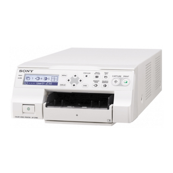
Part Names and Functions System Features Front The UP-27MD is a color video printer that captures images from an imaging output device such as video equipment and prints the images at A6 size with simple operations. It prints images by... - Page 12 When the menu screen is displayed: The Paper feed tray (page 20) screen display is hidden when this button is Load paper in this tray. Printouts stack in the pressed and held. tray above. Directional buttons (, , , ) ...
-
Page 13: Rear
RS-232C connector (page 16) Rear Connects to a computer for controlling the printer. Caution Do not come into contact with this terminal and patients at the same time. Doing so may result in a generation of voltage that can be harmful to patients if the unit is malfunctioning. - Page 14 Printer window display Reduced image setting Monitor display: Displays the number of reduced image screens. Printer window display: Displays the type of reduced image screens. Full-size image Two reduced images 1080p User01 Four reduced images Image capture position The current position of the pointer is indicated with an asterisk (*).
-
Page 15: Preparation
Connecting video equipment Preparation Note The printer cannot accommodate 4K video signal Connections or 3D video signal input. To enable printing, video equipment acting as an To AC power source input signal source must be connected along with a video monitor to display images or menus. Power cord The connection diagrams illustrate how to connect the input signal source to the printer, how... -
Page 16: Connecting A Video Monitor
Connecting a video monitor Connecting a foot switch Connect a video monitor as follows to view The printer can be controlled remotely by captured images and to check those to be printed. connecting the FS-24 Foot Switch (not supplied), or a computer. To AC power source Computer Power cord... -
Page 17: Color Printing Pack
Notes for preserving your printouts Color Printing Pack • Keep printouts in a dark and cool place. • Avoid using tape on printouts, leaving an eraser on printouts, or putting the printout on objects which contain plastic (desk mat, etc.) Compatible ink ribbon and paper •... -
Page 18: Loading The Ink Ribbon
Load the ink ribbon. Loading the Ink Align the two pegs on each side of the ink Ribbon ribbon with the slots on the ribbon tray. Note When using the printer for the first time, the thermal head may be set to its transport position. Be sure to turn on the printer and release the thermal head from its transport position before removing the ribbon tray. - Page 19 If the ink ribbon tears during use Note Cellophane tape, etc., can be used to repair a torn Do not touch the white tabs on the sides of ink ribbon so that the remainder of the ribbon can the ribbon tray. Doing so may result in be used.
-
Page 20: Loading The Paper
If the paper feed tray partition is raised, Loading the Paper lower it. Follow the steps below to load paper into the paper feed tray and to insert the tray into the printer. When using the printer for the first time, begin with step 2. - Page 21 Neatly stack and load the paper in the Insert the paper feed tray into the printer until paper feed tray, aligning the mark on it clicks into place. the protective sheet with the mark inside the tray. Notes Notes •...
-
Page 22: Selecting The Input Signal
Selecting the Input Note Do not pull on the metallic portion of the Signal stopper. Select the appropriate input signal format according to the signal from the video equipment connected to the input connectors on the rear of the printer. Note When settings are changed, it may take several seconds to switch. - Page 23 Use the or button to select the [Input Notes Setup] tab (), then the or button to select [Input Signal] (). • You cannot mix an HD video signal image and SD video signal image on the same memory page.
-
Page 24: Setting The Message Display Language
Use the or buttons to select the Setting the Message [Machine Setup] tab (), then the and buttons to select [Message Language] (). Display Language You can select either English or Japanese for the System Setup message language displayed on the video monitor. -
Page 25: Operation
Display the video from the video input source Operation on the monitor. This operation is done using the controls of the connected video equipment. Making Full-Size Image Printouts Print a full-size image on a single piece of paper. (This is known as “full-size image.”) The operations described here constitute the basic procedure for making a printout. - Page 26 On a video monitor If the printer does not print If you cannot print even when pressing the PRINT button, an error message is displayed on the video monitor and printer window display. Page A Printing Proceed as described in “Error/Warning Messages”...
-
Page 27: Making Printouts With A User Registered Settings
• Be sure not to spill alcohol or other volatile Use the or button to select the [Load organic solvents onto the printouts. User Setup] tab (), then the or button to select the user setting (). Making printouts with a user registered settings User Setup... - Page 28 To set the printout quantity by using the PRINT Use the or button to select the [Print QTY button Setup] tab (), then the or button to select [Print Quantity] (). 1, 2 User Setup Load Function Output Print Setup...
-
Page 29: Queuing Another Image While Printing
Repeatedly press the MEMORY PAGE button Note to select a memory page. When making multiple copies, the printer may stop printing due to printout conditions, and “Remove Printed Paper” appears. In such a case, remove printouts accumulated on the paper tray. The printer will resume printing the remaining copies automatically. -
Page 30: Making Variations Of Printouts
Selecting a memory page Making Variations of Printouts Memory page A memory area in which an image is captured is You can import and store several types of images called a memory page in this manual. in printer memory. Also, changing the print The number of usable memory pages depends on method allows you to create various types of the type of the reduced images selected and on... -
Page 31: Making A Printout Of Reduced Images - Multi Print
Press the MEMORY PAGE button repeatedly until Making a Printout of the desired memory page appears. Reduced Images – Multi Print You can make a printout of different types of images (reduced images). This section explains how to make a printout of reduced images. Configure the following settings to make a printout of reduced images: •... - Page 32 Use the or button to select the type of Select the type of reduced images to be reduced images. captured in memory by pressing the or button. Type Number of reduced images User Setup (names in parentheses are used in this manual) Load Function...
- Page 33 Making a printout with reduced images Use the or button to select the [Function Setup] tab (), then the or This section explains how to make printouts of button to select [Auto Live] (). reduced images using a printout of four reduced images as an example.
- Page 34 Output images from the video device (source Press the SOURCE/MEMORY button. images) onto the monitor. The source image appears on the video This operation is done using the controls of monitor. the connected equipment. Repeat steps 2 and 3 until you have captured When white frames have four images when the memory image been set, they appear on...
- Page 35 Display the [User Setup] screen according to Press the MENU button. the operations of step 1 described in “Making The [User Setup] screen is closed. printouts with a user registered settings” (page 27). Use the or button to select the [Print Setup] tab (), then the ...
-
Page 36: Making Printouts With A Caption
Non-text items Making Printouts with a Description Caption B.S. Deletes one character in front of the cursor. Moves the cursor position. On-screen keyboard Insert Inserts a character at the cursor position. An underline appears when turned on. A caption, such as comments, can be added to a Caps Switches between uppercase and lowercase printout below the image (up to 58 characters). - Page 37 Use the or button to select the [Print Press the EXEC button. Setup] tab (), then the or button to The character selected in step 4 appears at select [Caption Edit] (). the point where the cursor is positioned in the text input display area, after which the cursor moves to the next position.
-
Page 38: Zoom And Print Part Of An Image
To enter a space Zoom and Print Part of Move the cursor to the position where you want to enter a space, press the , , , or an Image button to select [Space], then press the EXEC button. Each the EXEC button is pressed, a single You can zoom the area of an image you need and space is inserted. - Page 39 [Zoom Mode]: [All] Zooms and prints the image area of all four 2, 3 screens. Image area 123456789 ABCDEFGH abcdefghij 123456789 ABCDEFGH abcdefghij 123456789 ABCDEFGH abcdefghij 123456789 ABCDEFGH abcdefghij Display the [User Setup] screen according to the operations of step 1 described in “Making printouts with a user registered settings”...
- Page 40 Fixed area Option Description Zooms and prints image area images in all screens. 123456789 ABCDEFGH abcdefghij Press the MENU button. 123456789 The [User Setup] screen is closed. ABCDEFGH First abcdefghij capture Press the CAPTURE button to capture an image. Follow steps 1 to 4 in “Making a printout with reduced images”...
- Page 41 To set the image zoom area User Setup In the [Print Area Setup] tab of the [User Setup] screen, select [Zoom Area], then use the or Print Area Save Initialize Setup User Setup User Setup button to select the zoom area. General Range User Setup Zoom Mode...
- Page 42 Setting Setting Description Setting Setting Description item range item range (default (default value) value) V Start 0 to 200 Sets the image capture V Start 0 to 200 Sets the image capture (4:3/5:4) (96) position (top edge) in the (4:3/5:4) position (top edge) in the vertical direction for an vertical direction for an...
-
Page 43: Deleting Images Stored In Memory
Deleting Images Stored Note The zooming size of the fixed area cannot be in Memory changed. The zoom size for 1920 × 1080 HD images is 832 × 624 (fixed). You can use the STOP/CLEAR button to delete individual reduced images captured to a memory page, or to delete all of the images from one or all of the memory pages. -
Page 44: Deleting Images Stored In Memory
Use the or button to select [Clear Button], User Setup then the or button to select the STOP/ CLEAR button function. Load Function Output Print Setup User Setup Setup Setup User Setup Clear Button All Images Clear Function Normal Load... - Page 45 To delete a single reduced image Notes • Even if you press the STOP/CLEAR button when Check the source image is displayed on the video Using [Clear Button] in the [Function Setup] tab of monitor, the memory image appears without the [User Setup] menu, set the STOP/CLEAR deleting images.
-
Page 46: Hiding The Screen Display On The Video Monitor
To set the screen display from the menu screen Hiding the Screen In [Information Display] on the [Output Setup] tab of the [User Setup] menu, you can hide setting Display on the Video information and configure settings to show the ink ribbon type and remaining ink ribbon. -
Page 47: Locking Controls
Press the MENU button. Locking Controls The [Printer Menu] screen is closed. When turned [On], only the [Lock] menu is enabled, and all other items are unavailable. You can lock printer controls to prevent unintentional button presses and setting Note changes. -
Page 48: Adjustment
Adjustment Menu Configuration The menu configuration on the printer is as follows. Bold text is the factory default setting. For further details, see the page indicated inside parentheses ( ). For details on the [User Setup] menu and [System Setup] items, see “Items That Can be Set on Menus” (page 51). Printer Menu Lock (page 47) - Page 49 User Setup Load User Setup User 01, User 02, User 03, User 04, User 05, User 06, (page 27) User 07, User 08, User 09, User 10 Function Setup Clear Button All Images Normal, Advance Image Clear Function Auto Live Output Setup Information Display Messages Display...
- Page 50 When [Aspect Ratio] is set to [SD (480i)] H Start 0 - 72 V Start 0 - 48 H Width 560 - 720 V Width 400 - 480 When [Aspect Ratio] is set to [SD (576i)] H Start 0 - 72 V Start 0 - 48...
-
Page 51: Items That Can Be Set On Menus
Functions that can be set Reference Items That Can be Set on page Menus Print Setup Selecting the type of printout (Multi Picture) Selecting whether or not white You can use the menu screen to set up the print to frames are added to multiple meet various specifications. -
Page 52: Basic Menu Operations
Functions that can be set Reference Basic Menu Operations page Machine Setting the message display Setup language (Message Language) 2, 3, 4, 5, 6 Setting whether or not to allow operation sounds and alarms (Beep) Adjusting the contrast of the printer window display (LCD Contrast) Adjusting the brightness of... - Page 53 Press the or button to select the desired Press the or button to select the desired tab. item. Example: Selecting the [Print Setup] tab Example: Selecting [Print Speed] in the [Print Setup] tab Use the or button to highlight the [Print Setup] tab. Use the ...
- Page 54 Use the or button to change the Example: Changing the [Monitor Color setting. Tone] adjustment value The current setting value To change the selection: Press the or button to select the desired option. System Setup Example: Selecting [Normal] speed Remote Color Input...
-
Page 55: Adjusting The Color And Sharpness
To return from the sub menu: Adjusting the Color and Select [ Back] on the top, then press the button. Sharpness Use the or button to highlight [ Back], then press the button. Compensating for source image Color Tone brightness, etc. -
Page 56: Matching The Video Monitor And Printout Color
Adjust the source image saturation, Matching the video monitor and brightness, and contrast. printout color Select the desired item, then perform the adjustment. If the video monitor and printout colors do no match and it is difficult to imagine what a printout Video Adjustment of the video monitor will look like, compare the Back... - Page 57 Display the [Output Setup] tab of the [User Display the [Monitor Color Tone] tab of the Setup] screen and use the or button to [System Setup] screen and adjust the video select [Source Image]. monitor color to match the printout. Select the desired item, then perform the adjustment.
-
Page 58: Adjusting The Printout Sharpness
Color adjustment Adjusting the printout sharpness Adjust the color balance using [Cyan-Red], You can adjust the printout color, contrast, [Magenta-Green], and [Yellow-Blue]. The sharpness, and tone (gamma). parameters can be adjusted in 15 steps. “0” is the standard value. Adjusting the color, contrast and Setting Setting Description... -
Page 59: When A Black Frame Or Lines Show Up On Printouts
To adjust the tone of the printout Display the [Print Area Setup] tab of [User Setup] screen, use the or button to select You can adjust the tone so that the details in the [General Range], then press the button. white or black areas of the source image are sharply defined in the print. -
Page 60: Printing To Match Paper Size
To eliminate a vertical black line on the left Aspect Setting Setting Default side: ratio item range value Adjust the capture position at the left edge of SD (576i) H Start 0 to 72 the image to be printed using [H Start]. V Start 0 to 48 H Width... -
Page 61: Adjusting The Color Balance
Use the or button to select [Resize To Fit], Display the [Color Correction] tab of the then the or button to select [On]. [System Setup] screen, use the or button to select [Color Balance], then press the General Range button. - Page 62 If you have already adjusted the color Select [Test Print], then press the EXEC button. balance, the previously adjusted values are Nine identical images from the area selected displayed. in step 2 are printed. Each image has a different color balance. Currently setting values of X and Y axes and the amount (This print operation can also be performed by of change between color balance items ([Bal Step])
- Page 63 Display the values of [Bal X] and [Bal Y] To make fine tune adjustments corresponding to the position selected in To fine tune the color balance within the step 5 by using the or button. current range, reduce the current [Bal Step] Example: When color balance 55 &...
-
Page 64: Specifying Colors For Adjustment
To make coarse adjustments Specifying colors for adjustment To coarsely adjust the color balance beyond the current range, increase the current [Bal Use the HSV function to select a specific color Step] value. within printouts for adjustment. You can specify red, yellow, green, cyan, blue, or magenta for If you change it from 5 to 10, the test print adjustment. - Page 65 Specify the color to adjust in [Color Sel]. Back Color Sel Red [R-Y] Press the or button to select [Color Sel], then use the Intensity Saturation or button to specify the color you want to adjust. Value Split9 Step...
- Page 66 Specify the parameter to adjust in [Split9]. Setting Description range (default value) Back 1 to 4 (2) Set a small value for fine tune Red [R-Y] Color Sel adjustments, and a large value for coarse adjustments. Intensity Saturation Select [Test Print], then press the EXEC button. Value Nine identical images from the area selected in step 2 are printed.
- Page 67 The changes in the parameter specified with Parameter adjustments [Split9] that appear in the test print are as Adjustments can be made in the range from follows. –16 to +16. “0” is standard. Option Description I (Intensity) Specifies the hue range selected in [ ] of [Color Sel].
- Page 68 To readjust parameter values To make coarse adjustments If the desired parameter values were not obtained To make adjustments beyond the current in step 8 of “Specifying colors for adjustment” parameter range, increase the current [Step] readjust the parameters. value. You can also fine tune adjustment following the same procedures.
-
Page 69: Setting The Hd Signal Aspect Ratio
Setting the HD signal aspect ratio Configuring Various Set the aspect ratio for the HD image signal input. Settings Display the [Input Setup] tab of the [System Setup] screen and use the or button to select [HD Aspect Ratio]. Registering a user settings You can set print specifications in each menu System Setup... -
Page 70: Returning User Settings To Factory Defaults
To activate the user setting and print Note Display the [Load User Setup] tab of the [User Setup] screen, select the desired user setting, and If you return registered setting values to factory press the EXEC button. defaults, the caption set in [Caption Edit] on the The printer operates according to the activated [Print Setup] tab of the [User Setup] menu will be user setting. -
Page 71: Displaying The Ink Ribbon Or Printer Setting Information
Select [All Reset], then press the EXEC button. Ink ribbon type and remaining prints Maintenance Backup Initialize Cleaning All Reset [EXEC] Remaining prints Ink ribbon type S: UPC-21S L: UPC-21L C: Cleaning ribbon End : MENU “All Reset” appears and all setting values on the printer are returned to factory defaults. - Page 72 Operation Operation Note type Although the REMOTE connector is compatible Each push of the foot switch Cap-Stop with the conventional REMOTE2 connector, captures an image to memory, and (Capture Stop) RM-5500 Remote Control Unit cannot be used when the last memory page is reached, “Press any button”...
-
Page 73: Setting The Communication Speed With A Printer
If not, press the SOURCE/MEMORY button to Adjusting the printer window display the source image. When multiple reduced display images are being captured, after the last image is captured, the printer starts printing (or queues printing), then switches to the next memory page. When it is hard to read the contents of the printer b) When multiple reduced images are being window display, adjust the contrast and... -
Page 74: Setting The Cleaning Message Display Function
• Correctly load the ink ribbon and paper, and Select [Head Cleaning Notify], then select ensure no error message is displayed. whether to display the message. Display the [Backup] tab of the [Maintenance] Maintenance screen. Backup Initialize Cleaning Select [Print Parameters] and press the EXEC Roller Cleaning [EXEC] button. -
Page 75: Miscellaneous
Printer location Miscellaneous Avoid placing or storing the printer in the following locations: • Direct sunlight Maintaining Printer • Humid locations • Extremely hot or cold locations Functionality • Locations with significant vibration • Dusty locations • Unstable locations In addition to the following precautions, be sure to For safety purposes, do not place anything on top refer to the safety warnings and notices at the of the printer, such as a monitor. -
Page 76: On Condensation
When the cabinet becomes dirty To unlock the thermal head Turn on the printer again. The thermal head When solvents such as benzene or thinner, or moves, and the ink ribbon can be loaded. acid, alkaline or abrasive detergent, or chemical cleaning cloths are used on the printer cabinet, the surface finish may be damaged. -
Page 77: Automatic Paper Feed Roller Cleaning
Note Note Once a protective sheet has been used as a The cleaning cartridge is reusable. Store it in cleaning sheet, do not use it again. the package to protect it from dust and other particles. Cleaning side Protective sheet Automatic paper feed roller (Cleaning sheet) cleaning... -
Page 78: Specifications
Control Connectors Specifications REMOTE (stereo mini jack) (1) For optional FS-24 Foot Switch connector Power Requirements RS-232C (D-sub 9 pin) (1) 100 V to 240 V , 50/60 Hz Supplied Accessories Input Current 1.7 A to 1.0 A Paper feed tray (1) Operating Temperature Stopper (1) 5 °C to 35 °C (41 °F to 95 °F) - Page 79 PERIOD OR AFTER EXPIRATION OF THE WARRANTY, OR FOR ANY OTHER REASON WHATSOEVER. • SONY WILL NOT BE LIABLE FOR CLAIMS OF ANY KIND MADE BY USERS OF THIS UNIT OR MADE BY THIRD PARTIES. • SONY WILL NOT BE LIABLE FOR THE...
- Page 80 Input signal format and output signal relation The output signal format for the input signal is as follows according to settings. For information on the input signal format selection method, see “Selecting the Input Signal” (page 22). For output signal setting instructions, see “Matching the video monitor and printout color” (page 56). Input signal Input signal Output signal...
- Page 81 Input signal Input signal Output signal Printer window selection display Source image Memory image [Input Signal] ([Source Image] settings) setting EE image Through image [General] setting [Through] setting [1080p] 480i 1080/59.94p 480i 1080/59.94p 1080/59.94i 1080/59.94p 1080/59.94i 1080/59.94p 1080i 1080/59.94p 1080/59.94p 1080/59.94p 1080/59.94p 1080p...
-
Page 82: Troubleshooting
Check “Error/Warning the following. If the printer still does not function Messages” and perform the normally, please contact your Sony dealer or local appropriate steps. See “Error/ authorized Sony service facility. Warning Messages” (page 84). • Paper that cannot be used with this printer has been loaded. - Page 83 Symptom Causes and remedies The printer ejects a The ink ribbon has been used up. blank sheet of Replace the ink ribbon. (page 18) paper, the ALARM Do not reuse the ejected paper. indicator lights and the message “Change Ribbon”. appears on the printer window display and the...
-
Page 84: Error/Warning Messages
Check Ribbon • The ink ribbon has torn. Repair the torn ink ribbon. (page 19) • If this message appears even though the ink ribbon is not torn, contact your Sony service facility or your Sony dealer. Remove Printed Paper The maximum number of printouts has accumulated on the paper tray. -
Page 85: Warning And Other Messages
Warning and other messages For warning or other messages, the message will be displayed and the ALARM indicator will remain off. Follow the instructions in the message. Message Causes and remedies Check Input Signal • The source image signals from the input device (VTR, video camera, etc.) do not match the [Input Signal] settings in the [Input Setup] tab of the [System Setup] menu. -
Page 86: Clearing A Paper Jam
Load the paper properly. Clearing a paper jam If the ALARM indicator on the ribbon door panel lights after printing starts, or if “Remove Paper” or “Check Paper” appears on the printer window display, a paper jam may have occurred inside the printer. - Page 87 Be sure to reattach the base plate. The printer cannot print with the base plate removed. If a paper jam still cannot be cleared Consult your Sony dealer or your Sony service facility. Do not attempt to remove the paper by force.
-
Page 88: License
Project (www.freetype.org). All rights reserved. License """ Please replace <year> with the value from the FreeType version you actually use. “zlib”, “FreeType” and “ttfautohint” software are Legal Terms provided in this unit. We provide this software =========== based on license agreements with their owners of 0. - Page 89 haven't found anything to help you in the documentation. 1. No Warranty o freetype-devel@nongnu.org -------------- Discusses bugs, as well as engine internals, design issues, THE FREETYPE PROJECT IS PROVIDED `AS IS' WITHOUT WARRANTY OF ANY specific licenses, porting, etc. KIND, EITHER EXPRESS OR IMPLIED, INCLUDING, BUT NOT LIMITED TO, WARRANTIES OF MERCHANTABILITY AND FITNESS FOR A PARTICULAR Our home page can be found at PURPOSE.