Table of Contents
Advertisement
Quick Links
Advertisement
Chapters
Table of Contents

Related Manuals for Eaton EX Pulsar Series


Summary of Contents for Eaton EX Pulsar Series
- Page 1 . e a t o n . c o m www.eaton.com 2200 RT 2U 2200 RT 2U 3000 RT 2U 3000 RT 2U EXB RT 3U EXB RT 3U インストレーションおよび 取扱説明書 Installation and User Manual Installation and User Manual English 日本語...
- Page 2 86-86710-00...
- Page 3 2200 RT 2U 3000 RT 2U 3000 RT 2U EXB RT 3U EXB RT 3U インストレーションおよび 取扱説明書 Installation and User Manual English Pulsar Series Pulsar Series 版権 ©2010 年 EATON 社 版権所有。 弊社の製品についてご不明な点がございましたら、 下記までお問合せください。Email:JapanSales@Eaton.com Website:http://powerquality.eaton.com/Japan 86-86710-00 A02 UM.indd 1 14/01/2009 10:56:17...
-
Page 5: Table Of Contents
目次 はじめに ····································································································································1 安全上の重要な注意事項 ········································································································· 2 記号説明 ····································································································································3 外観 1.1 標準形態····································································································································5 1.2 背面パネル ································································································································6 1.3 操作パネル ································································································································6 インストレーション 2.1 開梱と付属品の確認··················································································································7 2.2 縦 使用時のインストレーション·······························································································8 2.3 ラックマウント使用時のインストレーション ··········································································8 2.4 通信ポート ································································································································9 2.5 FlexPDUモジュール(配電ユニット)[オプション]との接続 ················································10 2.6 ホットスワップMBP(メンテナンス・バイパス)モジュール[オプション]との接続 ············10 2.7 FlexPDUまたはホットスワップMBPモジュールがない時のUPS接続 ··································· 11 運転 3.1 起動と通常運転... -
Page 7: はじめに
はじめに このたびはEATON社の製品をご購入いただき、誠にありがとうございます。 EXシリーズは弊社が細心の注意をはらい安全を期して設計したものです。 本装置の全ての機能を十分にご理解頂くために、この取扱説明書をよくお読みください。 またお読みになったあとは、必ず保管してください。 ご注意:この装置は、一般財団法人VCCI協会の基準に基づくクラスAレベル装置です。この装置を家庭環境で 使用すると電波妨害を引き起こすことがあります。この場合には使用者が適切な対策を講ずるよう要求される ことがあります。 もし、IIIまたはIV類の過電圧環境で本装置を取り付けざるを得ない場合は、上流の設備に対し、追加で過電圧 保護を付加しなければなりません。 本装置(UPS)をご使用前に必ずこの取扱説明書および注意書きをお読みになり、 本書の指示に従い、操作し てください。 EATON社のEX全シリーズ製品とオプションパーツをお知りになりたい場合は、当社のウェブサイトをご覧く ださい:www.eaton.com(英語)。またはEATON社UPS販売代理店にお問い合わせください。 環境保全 EATON社は環境保全政策を推進しています。 本製品は当社のエコデザイン方式で開発されたものです。 有害物質 本製品はCFC、HCFC及びアスベストは含まれていません。 梱包 リサイクルを促進するために、各包装材は分類処理をしてください。 » 本製品に使用しているダンボール紙は 50% 以上がリサイクル品を使用しています。 » 包装材はポリエチレン(PS)を使用しています。 » 包装材はリサイクルできます。それぞれに相応の識別記号が記してあります。 記号 材料 略語 番号 ポリエチレンテレフタレート HDPE 高密度ポリエチレン ポリ塩化ビニル LDPE 低密度ポリエチレン... -
Page 8: 安全上の重要な注意事項
» IEC 61000-4-4(EFT) » IEC 61000-4-5(Surge) » IEEE-C6241 Category B(Ring wave) » IEC 61000-4-6(Electromagnetic field) » IEC 61000-4-8(Conducted magnetic field) » 安全上のご注意 UPS(無停電電源装置)の本体には蓄電池(バッテリ)が装備されています。システムのACパワーを切断しても、電源コン » セントは帯電している可能性があります。 UPSは危険な電圧レベルです。EATON社が認めた有資格者以外は筐体を開けないでください。 » UPSは確実にアース接続してください。(必ず付属のACケーブル(3Pプラグ)をご使用ください。)取り付ける際、正しく » UPSと接続している設備(負荷)の特性パラメータを検査する必要があります。UPSと接続される設備の漏洩電流の合計は 3.5mAを超えてはなりません。 UPSやそのバッテリを屋内で使用される場合は、必ず換気し、管理監督された環境でご使用ください。 » UPSに内蔵されているバッテリには少量の有毒物質が含まれています。事故を未然に防ぐ為に、下記の事項を必ずお守りくだ » さい: ーバッテリを燃やさないでください。爆発の恐れがあります。 ーバッテリを分解しないでください。電解液は目と皮膚に危険です。 ーバッテリを廃棄する際は、各国内法、各種条例・規則に従って廃棄してください。 ーショートすると非常に大きな電流が流れる可能性があります。取り扱う際には、腕時計、指輪、プレスレット等のいかなる... -
Page 9: 記号説明
環境 » 本製品は環境に配慮した設計になっています。 本製品はクロロフルオロカーボン(CFC)またはハイドロクロロフルオロカーボン(HCFC)は、含まれていません。 » 耐用年数の終了したUPSのリサイクルに関して: EATON社は認定された会社を通じて、すべての適用規則に従い、耐用年数の終了したすべてのEATON社製UPS製品を有償にて リサイクルいたします。(お近くのEATON社販売代理店にお問い合わせください) » 梱包:各自治体の条例等に従い、本装置(UPS)の梱包材料をリサイクルしてください。 警告:本製品は鉛バッテリが使用されています。鉛は環境に影響がある物質です。廃棄処分等は専門会社に依頼してください。 記号説明 常に従われなければならない重要な指示(危険!、警告、注意!) 情報、アドバイス、ヘルプ 目で見る確認 確認 音による確認 LEDランプが消灯します LEDランプが点灯します LEDランプが点滅します... -
Page 11: 標準形態
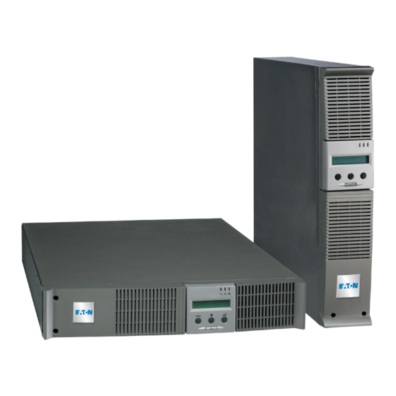
1. 外観 1. Presentation 1. Presentation Standard Positions 標準形態 Standard Positions Tower Position Tower Position 縦 使用 Dimensions (H x W x D) in inches Dimensions (H x W x D) in inches EX 2200 RT 2U 17.3 x 3.38 x 25.2 EX 2200 RT 2U 17.3 x 3.38 x 25.2 寸法(高×幅×奥行)... -
Page 12: 背面パネル
1. Presentation 1. 外観 1. Presentation Rear Panels 1. Presentation 背面パネル Rear Panels EX 2200 / 3000 / 3000 XL Rear Panels EX 2200 / 3000 / 3000 XL EX 2200 EX 2200 / 3000 / 3000 XL (1) USB communication port USB通信ポート... -
Page 13: インストレーション
2. Installation 2. インストレーション Unpacking and Contents Check 開梱と付属品の確認 (30) EX 2200 or 3000 UPS (30) EX 2200 / 3000 UPS(本体) 1台 (38) 19 インチラックマウントキット 1組 (38) Mounting kit for 19-inch bays. (33) RS232 communications cable (33) RS232 通信ケーブル 1本 (39) 縦使用時の補助キット ... -
Page 14: 縦 使用時のインストレーション
Follow steps 1 to 4 for module mounting on the rails. Follow steps 1 to 4 for module mounting on the rails. ガイドレールにモジュールを取り付ける際、ステップ 1-4 の操作順に従ってください。 The rails and necessary hardware are supplied by EATON. ガイドレールと必要な部品は同梱されています。 The rails and necessary hardware are supplied by EATON. -
Page 15: 通信ポート
RS232 (2) communication port on the UPS. に接続します。 RS232 (2) communication port on the UPS. The UPS can now communicate with 2. 通信ケーブル(33)または(34)のもう一端をUPS The UPS can now communicate with EATON power management software. のUSB(1)またはRS232(2)通信ポートに接続し EATON power management software. ます。 Installation of the communication cards (optional) 通信カードのインストレーション[オプション]... -
Page 16: Flexpduモジュール(配電ユニット)[オプション]との接続
2. Installation 2. インストレーション FlexPDUモジュール(配電ユニット)[オプション]との接続 Connections with a FlexPDU (Power Distribution Unit) Module (optional) 2. Installation 1. UPS電源ケーブル(10)をAC電源に接続しま EX 3000 す。 1. Connect the UPS powercord (10) to the AC Connections with a FlexPDU (Power Distribution Unit) Module (optional) power source. 2. -
Page 17: FlexpduまたはホットスワップMbpモジュールがない時のUps接続
20A (or 30A on EX 3000) outlet (7) as during operation on battery power and shown at left for EX 2200. thus optimise the available backup time, ます。 the EATON communications software is To program shutdown of outlets (8) required. (8)のプログラマブルコンセントは、プログラ during operation on battery power and ムの組み方によっては、バックアップ運転時... - Page 18 (このページは空白です) 86-86710-...
-
Page 19: 起動と通常運転
If UPS personalization is desired, it is advised to enter the personalization mode at this time. によって、当モードに入ることができます。 This mode may be entered using the buttons on the control panel or the Personal Solution-Pac Software (Windows) included on the Solution-Pac CD-ROM provided by EATON. 86-86710-00EN A02 - Page 17 86-86710-00 A02 UM.indd 17... -
Page 20: バッテリパワーによる運転
3. Operation 3. 運転 3. Operation 3. Operation Operation on Battery Power バッテリパワーによる運転 Operation on Battery Power Operation on Battery Power Transfer to battery power Transfer to battery power Transfer to battery power Transfer to battery power Transfer to battery power Transfer to battery power バッテリ給電への切り換え... -
Page 21: Upsのリモート機能
3. 運転 3. Operation 3. Operation UPSのリモート機能 Using the UPS Remote Control Functions Using the UPS Remote Control Functions EXは 2種類のリモート機能を選択できます。 EX has the choice of two remote control options. EX has the choice of two remote control options. » RPO(Remote Power Off): リモートパワーオフ機能はリモートでUPSに接続されたすべての機器の電源を切断することが RPO: Remote Power Off allows a remote contact to be used to disconnect all the equipment connected to the できます。... - Page 22 (このページは空白です)...
-
Page 23: メンテナンスとカスタマイズの設定
4. メンテナンスとカスタマイズの設定 4. Access to Maintenance and Personalization Data ディスプレイ表示 Display Organization 状態とアラーム 状態とアラーム Status and Alarms Status and Alarms 測定結果 UPSの入力測定結果 UPSの出力測定結果 Measurements バッテリ測定結果 UPS input measurements UPS output measurements Battery measurements カスタマイズ設定 ローカルカスタマイズ設定 出力のカスタマイズ設定 Personalization オン/オフのカスタマイズ設定 Local personalization バッテリのカスタマイズ設定... -
Page 24: 外部ソフトウェアによるカスタマイズ設定
機能 メーカー設定 オプション 備考 バッテリ試験間隔時間 毎週試験 試験しません/毎日試験/毎月試験 AC電源が復帰する時、 バッテリモジュール 0-200A時 バックアップ時間選択 UPSを自動再起動します。 の数の自動検出 当該機能の使用を停止した時、 バッテリの過度放電保 EATON社の保証の対象外となりま 使用可 使用不可 護 す。 外部ソフトウェアによるカスタマイズ設定 » Solution-PacCD-ROMをPCのドライブに挿入してください。 » 最初のナビ画面より「Point to Point solution」を選択し、取扱説明書に従い、Personal Solution-Pacソフトウェアをインス トールしてください。 » 「Settings」→「Advanced Settings」→「UPS Settings」を選択します。 ご注意:Personal Solution-Pacソフトウェアは、Linux/Unix/MacOSをサポートしていません。 (1). UPSパワーオフの時のみに、これらのパラメータを変更できます。 (2). 周波数コンバータ機能を使用する時、バイパスの機能を停止します。... -
Page 25: メンテナンス
5. メンテナンス トラブルシューティング LEDランプ(21) または(22) が点灯すると、故障が発生したことが考えられます。 Escapeボタン (24) で警報音を停止してくだ さい。 指示 診断 解決方法 UPSが起動できない場合、アルフ AC入力電源がつながっていない、ま » AC電源の有無を確認してください。 ァベット数字ディスプレーが次の たはUPS出力コネクタにつながって » UPSとAC入力電源が正確に接続してい ように表示します:COLD START います。 るかを確認してください。 NOK CHECK AC WIRING(コール ドスタートが失敗しました。AC配 線を検査してください) LEDランプ (22) が点灯し、UPS背 AC入力電源が逆相が発生しました。 極性と接地システムを検査してくださ 面のSWF LEDランプ (11) も点灯 UPSが起動できません。... -
Page 26: バッテリモジュールの交換
5.メンテナンス ホットスワップMBPモジュール付のUPSのトラブルシューティング 指示 診断 解決方法 UPSとホットスワップMBPモジュールの » 接続機器がホットスワップMBPモジ ホットスワップMBPモジュールの スイッチ (53) をBypass位置に設 ュールでなく、UPS側に接続されてい 間の配線を検査してください(第2.6節 置しても、負荷に給電しません。 る。 をご参照ください)。 » AC電源ケーブルがホットスワップ MBPモジュール側でなく、UPS側に接 続されている。 » UPSが停止状態である。 » UPSを起動してください。 ホットスワップMBPモジュールの スイッチ (53) をNormal位置に設置 » UPSとホットスワップMBPモジュー » UPSとホットスワップMBPモジュール ルの間の配線は不適切です。 の間の配線を検査してください(第2.6 しても、負荷に給電しません。 節をご参照ください)。 AC電源に故障が発生した際、負荷 » ホットスワップMBPモジュールのス »... - Page 27 新バッテリモジュールの取付 Carry out the above instructions in reverse order. 上記手順の逆順で行ってください w To ensure safety and high performance, use only batteries supplied by EATON. » 安全と高性能を保証するため、必ずEATON社指定のバッテリを使用してください。 w Take care to firmly press together the two parts of the connector during remounting.
-
Page 28: ホットスワップMbpモジュール付のUpsのメンテナンス
5.メンテナンス 5. Troubleshooting ホットスワップMBPモジュール付のUPSのメンテナンス Maintenance on a UPS Equipped With the HotSwap MBP Module ホットスワップMBPモジュールにより、接続され た負荷に影響しない状況下で、UPSを修理または 交換することが可能となります(ホットスワップ The HotSwap MBP module makes possible 機能)。 to service or even replace the UPS without affecting the connected loads (HotSwap メンテナンス: function). 1. スイッチ(53)をBypass位置に設置します。 Maintenance: ホットスワップMBPモジュールの赤色LED ランプ(52) が点灯し、負荷はAC電源から直... -
Page 29: 技術規格
6. Appendices 6.付録 技術規格 Technical Specifications フィルタ コンバータ インバータ フィルタ チャージャ DC-DC インバータ バッテリ EX 2200 EX 3000 EX 2200 EX 3000 1890 VA 2500VA 出力パワー 2100 VA 3000 VA 1480 W 2150 W Output power 1650 W 2550 W AC入力電源... -
Page 30: プログラマブルコンセントのプログラミング
Programming the Programmable Outlets 1. 「スタートメニュー/プログラム/EATON/Personal Solution Pac/Settings」を左クリックするか、SYS Tray(システム To open the Setting window, left-click on Start Menu / Programs / EATON / Personal Solution Pac / Settings, トレー)のPSP電源プラグを右クリックして、「Settings」ウインドウを開きます。 or right-click on the PSP power plug located in the SYS Tray. - Page 31 6.付録 6. Appendices 4. 各プログラム可能コンセントに対し、ステップ3(前ページ)を繰り返します。 Repeat step 3 for each programmable outlet. 5. 変更後、「Apply」ボタンをクリックします。 After making the changes,s click on the “Apply” button. ユーザーは、タイトルが「Shutdown timer」の部分について、停止後、電源にコンセントが共有され、引き続き給電する期間 The section entitled “Shutdown timer” allows the user to define how long the powershare outlet should provide を設定できます。...
-
Page 32: 用語集
6.付録 用語集 AC電源からのバイパス配線はUPSがコントロールし、UPSに過負荷または故障が発生した バイパスAC入力 際、直接負荷に給電します。 バックアップ時間 バッテリパワーで運転するUPSが負荷に給電できる時間。 UPS内部試験(バッテリ状態の検査)。 バッテリ試験 UPS出力に接続された装置。 設備 過度放電 許容限度を超えたバッテリ放電で、バッテリに回復不可能な損壊を引き起こします。 FlexPDU Power Distribution Unit。配電するための電源タップです。種類によってタイプの異なるコン セント形状となります。 UPS入力と出力の間にAC電源の周波数(50 Hz -> 60 Hzまたは60 Hz -> 50 Hz)の切り換え 周波数コンバータ に用いる運転モードです。 ホットスワップMBP メンテナンスに用いるUPSの手動バイパス接続モジュールです。モジュールによってタイプ の異なるコンセント形状なります。 バッテリパワー低下の警告 パワー低下のバッテリ電圧レベルを表示します。負荷はまもなく給電が停止するので、ユー ザーは措置を講じなければなりません。 液晶ディスプレィ。 通常AC入力 通常条件下でUPSに給電するAC電源です。 負荷率 負荷値とUPSの最大出力のパワーの比率です。 メーカー設定の一部のUPSパラメータを変更できます。... - Page 33 86-86710-00 A02 86-86710-00 A02 UM.indd 34 14/01/2009 10:56:53...
- Page 34 86-86710-00...
- Page 35 Installation and User Manual Installation and User Manual English Pulsar Series Pulsar Series Copyright © 2010 EATON All rights reserved. For Technical Support, Customer Care Center, or Customer FAQ, Please contact us: Email: JapanSales@Eaton.com Website: http://powerquality.eaton.com/Japan 86-86710-00 A02 UM.indd 1 14/01/2009 10:56:17...
- Page 37 Contents Introduction ........................1 Important Safety Instructions .................... 2 Symbol Usage ........................3 1. Presentation 1.1 Standard Positions ......................5 1.2 Rear Panels ........................6 1.3 Control Panel ........................6 2. Installation 2.1 Unpacking and Contents Check ..................7 2.2 Installation in Tower Position ..................
-
Page 39: Introduction
Before installing EX, please read the booklet on the required safety instructions. Then follow the indications in this manual. To discover the entire range of EATON products and the options available for the EX range, we invite you to visit our web site at www.eaton.com or contact your EATON representative. -
Page 40: Important Safety Instructions
This is a Class A product based on the standard of the Voluntary Control Council for Interference (VCCI) for information technology equipment. If this equipment is used in a domestic environment, radio disturbance may arise. When such trouble occurs, the user may be required to take corrective actions. -
Page 41: Symbol Usage
Symbol Usage Important instructions that must always be followed. Information, advice, help. Visual indication. Action. Audible signal. LED off. LED on. LED flashing. 86-86710-00EN A02 - Page 7 86-86710-00 A02 UM.indd 7 14/01/2009 10:56:20... - Page 42 86-86710-00...
-
Page 43: Presentation
1. Presentation Standard Positions Tower Position Dimensions (H x W x D) in inches Dimensions (H x W x D) in inches EX 2200 RT 2U 17.3 x 3.38 x 25.2 EX 2200 RT 2U 17.3 x 3.38 x 25.2 EX 3000 RT 2U 17.3 x 3.38 x 25.2 EX 3000 RT 2U... -
Page 44: Rear Panels
1. Presentation Rear Panels EX 2200 / 3000 / 3000 XL EX 2200 (1) USB communication port (2) RS232 communication port (3) Connector for automatic recognition of an additional battery module (4) Slot for optional communication card (5) Connector for remote ON/OFF and RPO (Remote Power Off) control (6) Connector for additional battery module (7) L5-20R (or L5-30R for EX 3000) receptacle... -
Page 45: Installation
2. Installation Unpacking and Contents Check (30) EX 2200 or 3000 UPS (38) Mounting kit for 19-inch bays. (33) RS232 communications cable (39) 2 supports for the upright position. (34) USB communications cable (40) FlexPDU module (optional) (42) NMC communication card (optional) (36) Solution-Pac CD-ROM (37) Documentations supplied depending on the UPS (43) HotSwap MBP module (optional) -
Page 46: Installation In Tower Position
It is advised to first install the battery module, then the power module above. Follow steps 1 to 4 for module mounting on the rails. The rails and necessary hardware are supplied by EATON. 86-86710-00EN A02 - Page 12 86-86710-00 A02 UM.indd 12... -
Page 47: Communication Ports
(33) or (34) to the USB (1) or RS232 (2) communication port on the UPS. The UPS can now communicate with EATON power management software. Installation of the communication cards (optional) It is not necessary to shutdown the UPS before installing a communications card. -
Page 48: Connections With A Flexpdu (Power Distribution Unit) Module (Optional)
2. Installation Connections with a FlexPDU (Power Distribution Unit) Module (optional) EX 3000 1. Connect the UPS powercord (10) to the AC power source. 2. Connect the input cord of the FlexPDU module (48) to the UPS outlet (9). The cord and the outlet are marked in red. -
Page 49: Ups Connection Without A Flexpdu Or Hotswap Mbp Module
EATON communications software is required. Note: The UPS charges the battery as soon as it is connected to the AC power source, even if button (27) is not pressed. - Page 50 (This page left blank intentionally) 86-86710-00...
-
Page 51: Operation
If UPS personalization is desired, it is advised to enter the personalization mode at this time. This mode may be entered using the buttons on the control panel or the Personal Solution-Pac Software (Windows) included on the Solution-Pac CD-ROM provided by EATON. 86-86710-00EN A02 - Page 17 86-86710-00 A02 UM.indd 17... -
Page 52: Operation On Battery Power
3. Operation Operation on Battery Power Transfer to battery power Transfer to battery power w The connected devices continue to be supplied by the UPS when AC power is no longer available. The necessary energy is provided by the battery. w LEDs (20) and (21) go ON. -
Page 53: Using The Ups Remote Control Functions
3. Operation Using the UPS Remote Control Functions EX has the choice of two remote control options. RPO: Remote Power Off allows a remote contact to be used to disconnect all the equipment connected to the UPS from the power supply. Restarting the UPS requires manual intervention. - Page 54 (This page left blank intentionally) 86-86710-00...
-
Page 55: Access To Maintenance And Personalization Data
4. Access to Maintenance and Personalization Data Display Organization Status and Alarms Status and Alarms Measurements UPS input measurements UPS output measurements Battery measurements Personalization Local personalization Output personalization On/Off personalization Battery personalization Access to Measurements Press the scroll button (25) to access any status conditions and alarms, then the measurements for voltage, current, frequency, power output and battery backup time. -
Page 56: Personalization Using External Software
Automatic detection of UPS restarts automatically when 0 to 200 Ah backup time number of battery modules Normal AC source is restored. Battery protection When function disabled, EATON against excessive Enabled Disabled warranty no longer applies. discharges Personalization Using External Software Insert the Solution-Pac CD-ROM in the drive. -
Page 57: Maintenance
5. Maintenance Troubleshooting If LED (21) or (22) is ON, a fault or an alarm has occurred. Use the escape button (24) to stop the audio alarm. Indication Diagnostic Correction The UPS does not start, the LCD The AC input power is not w Check AC power availability. -
Page 58: Battery Module Replacement
5. Troubleshooting Troubleshooting a UPS equipped with the HotSwap MBP module Indication Diagnostic Correction The load is no longer supplied Check the wiring between the UPS w The protected devices are con- when the rotary switch (53) on nected to the UPS output instead and the HotSwap MBP module (see the HotSwap MBP module is set of to the HotSwap MBP module. - Page 59 Mounting the new battery module Carry out the above instructions in reverse order. w To ensure safety and high performance, use only batteries supplied by EATON. w Take care to firmly press together the two parts of the connector during remounting.
-
Page 60: Maintenance On A Ups Equipped With The Hotswap Mbp Module
5. Troubleshooting Maintenance on a UPS Equipped With the HotSwap MBP Module The HotSwap MBP module makes possible to service or even replace the UPS without affecting the connected loads (HotSwap function). Maintenance: 1. Set switch (53) to the Bypass position. The red LED (52) on the HotSwap MBP module goes ON, indicating that the load is supplied directly with AC power. -
Page 61: Appendices
6. Appendices Technical Specifications Filter Converter Inverter Filter Charger DC-DC Inverter Battery EX 2200 EX 3000 EX 2200 EX 3000 2100 VA 3000 VA 1890 VA 2500 VA Output power Output power 1650 W 2550 W 1480 W 2150 W Electrical supply network Electrical supply network 100-120 V... -
Page 62: Programming The Programmable Outlets
6. Appendices Programming the Programmable Outlets To open the Setting window, left-click on Start Menu / Programs / EATON / Personal Solution Pac / Settings, or right-click on the PSP power plug located in the SYS Tray. Click on the “+” symbol next to “UPS Settings” to expand the “UPS Settings” section. - Page 63 6. Appendices Repeat step 3 for each programmable outlet. After making the changes,s click on the “Apply” button. The section entitled “Shutdown timer” allows the user to define how long the powershare outlet should provide power after a power loss. To configure the powershare to power off at the same time as the main outlets: Set the “The group of outlet is powered OFF after”...
-
Page 64: Glossary
6. Appendices Programming the Programmable Outlets Glossary To open the Setting window, left-click on Start Menu / Programs / EATON / Personal Solution Pac / Settings, or right-click on the PSP power plug located in the SYS Tray. Bypass AC input Bypass line from the AC power source, controlled by the UPS, used to directly supply the Click on the “+”... - Page 65 2009 10:56:32 2009 10:56:32...
- Page 66 614-03760-01 86-86710-00 A02 86-86710-00 A02 UM.indd 34 14/01/2009 10:56:53...