
Related Manuals for Alcatel-Lucent OmniSwitch 6865-P16X


Summary of Contents for Alcatel-Lucent OmniSwitch 6865-P16X
- Page 1 Alcatel-Lucent Enterprise OmniSwitch 6865 Hardware Users Guide Part No. 060435-10, Rev P July 2021...
- Page 2 This user guide document s OmniSwit ch 6865 hardware, including chassis and associat ed component s. The specif icat ions described in t his guide are subj ect t o change wit hout not ice. The Alcat el-Lucent name and logo are t rademarks of Nokia used under license by ALE. To view ot her t rademarks used by af f iliat ed companies of ALE Holding, visit : www.
-
Page 3: Table Of Contents
Contents Cont ent s ....................... 0 About This Guide 1 Relat ed Document at ion . - Page 4 Inst alling Power Supplies................... . 28 Inst alling Power Supplies f or Side Mount Trays .
- Page 5 Cl ass A Warning f or Taiwan and Ot her Chinese Market s..........70 Translat ed Saf et y Warnings .
-
Page 6: About This Guide
About This Guide Related Documentation • Omni Swi t ch CLI Ref er ence Gui de • Omni Swi t ch AOS Swi t ch Management Gui de • Omni Swi t ch AOS Net work Conf i gur at i on Gui de •... -
Page 7: Chassis And Power
1 Chassis and Power OmniSwit ch 6865 Hardware Users Guide... -
Page 8: Omniswitch 6865-P16X
The Alcat el-Lucent Ent erprise OmniSwit ch® 6865 series are Gigabit Et hernet (GigE) and 10 Gb Et hernet (GigE) swit ches designed f or demanding elect rical and severe t emperat ure environment s. OmniSwitch 6865-P16X (Side Mounted Power Supply Tray Shown) OmniSwit ch 6865-P16X Chassis Specif icat ions... -
Page 9: Chassis Front Panel
OmniSwit ch 6865-P16X Chassis Specif icat ions 1G/ 10G SFP+ Port s 1588v2 Capabilit y Support ed PoE Power Budget “ Power over Et hernet Budget ” on page 57 f or more inf ormat ion. Power Consumpt ion (idle) Chassis Front Panel Front Panel Descript ions (Lef t t o Right ) Console (RJ45) -
Page 10: Chassis Rear Panel
Chassis Rear Panel Rear Panel Descript ions (Lef t t o Right ) Power Supply Connect or Power Supply Connect or Grounding Block Chassis Ground OmniSwit ch 6865 Hardware Users Guide... -
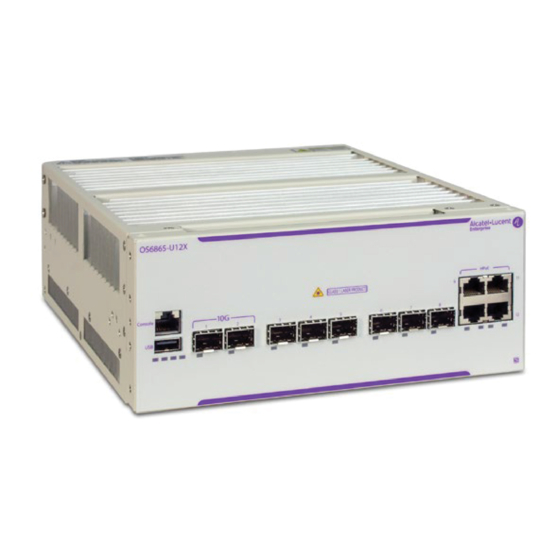
Page 11: Omniswitch 6865-U12X
OmniSwitch 6865-U12X OmniSwit ch 6865-U12X Chassis Specif icat ions Fans None Power Supplies 2 t ot al (1 primary PSU and 1 opt ional backup PSU) Rack Unit Dimensions 2 RU (Addit ional clearance is required f or airf low, “... -
Page 12: Chassis Front Panel
Chassis Front Panel Front Panel Descript ions (Lef t t o Right ) Console (RJ45) For console or modem USB Type A For st orage devices t hat can download code or save conf igurat ion inf ormat ion, such as f lash-based pen drives or ext ernal hard drives. -
Page 13: Chassis Rear Panel
Chassis Rear Panel Rear Panel Descript ions (Lef t t o Right ) Power Supply Connect or Power Supply Connect or Grounding Block Chassis Ground OmniSwit ch 6865 Hardware Users Guide... -
Page 14: Omniswitch 6865-U28X
OmniSwitch 6865-U28X OmniSwit ch 6865-U28X Chassis Specif icat ions Fans None Power Supplies 2 t ot al (1 primary PSU and 1 opt ional backup PSU) Rack Unit Dimensions 1 RU (Addit ional clearance is required f or airf low, “... -
Page 15: Chassis Front Panel
Chassis Front Panel Front Panel Descript ions (Lef t t o Right ) Console (RJ45) For console or modem USB Type A For st orage devices t hat can download code or save conf igurat ion inf ormat ion, such as f lash-based pen drives or ext ernal hard drives. -
Page 16: Chassis Rear Panel
Chassis Rear Panel Rear Panel Descript ions (Lef t t o Right ) Power Supply Connect or Power Supply Connect or Grounding Block Chassis Ground Port s 29 and 30 QSFP+ VFL Port s OmniSwit ch 6865 Hardware Users Guide... -
Page 17: Power Supplies
Power Supplies OS6865-BP - 180W AC Power Supply Power Supply Rear Power Supply Front OS6865-BP - 180W Power Supply Descript ion Modular AC power supply. Up t o t wo (2) power supplies may be inst alled. Dimensions (H x W x L) 5. -
Page 18: Os6865-Bp-D - 180W/ 140W Dc Power Supply
OS6865-BP-D - 180W/ 140W DC Power Supply Power Supply Front Power Supply Rear OS6865-BP-D 180W/ 140W DC Power Supply Descript ion Modular DC power supply. Up t o t wo (2) power supplies may be inst alled. Dimensions (H x W x L) 5. -
Page 19: Dc Power Supply Connection
DC Power Supply Connection Connecting a DC Cable Harness to the Chassis Power Supply When plugging in t he cable, insert t he connect or end of t he cable harness int o t he power supply connect or unt il it clicks f irmly int o place. This is an indicat ion t hat t he connect or is secure and properly seat ed. - Page 20 A clamp inside each slot keeps t he power wire t ight ly in place during operat ion. The DC power supply connect or has side screws t hat can be used t o remove t he connect or if required. Installing DC Power Source Wire Leads These inst ruct ions describe how t o connect your 3-wire DC power source t o t he power connect or on your DC power supply.
-
Page 21: Dying Gasp
t erminal of t he DC power supply. This rule always applies t o bot h -24V, and -48V input volt ages, regardless of t he polarit y signs shown on t he power supply specif icat ion label s such as: -48V, +24V, or -24V. -
Page 22: Syslog Message
Syslog Message As soon as t he power f ailure is det ect ed, t he f ollowing Syslog message is sent t o t he f irst t hree conf ig- ured Syslog servers, along wit h t he t ime of t he f ailure: Dying Gasp Power Failure Event Occurred Use t he command t o add a Syslog st at ion. -
Page 23: Getting Started And Installation
2 Getting Started and Installation OmniSwit ch 6865 Hardware Users Guide... -
Page 24: Getting Started
Getting Started Preparing for the Installation Alcat el-Lucent Ent erprise product s must be inst alled by a prof essional inst aller. It is t he responsibilit y of t he inst aller t o comply wit h product specif icat ions and all appl icable local and nat ional codes. When preparing f or inst allat ion, unpack t he product as close as possible t o t he locat ion where it will be inst alled. - Page 25 Additional Electrical Requirements The swit ches have t he f ollowing general el ect rical requirement s: • AC and DC power supply support • Each supplied AC power cord is 2 met ers (approx. 6. 5 f eet ). Do not use ext ension cords. •...
-
Page 26: Providing Air Flow And Minimum Recommended Clearances
Providing Air Flow and Minimum Recommended Clearances • Swit ches operat ing in an environment at or above 65° C require air f low. • Swit ches operat ing in an environment below 65° C do not require airf low. •... - Page 27 OmniSwit ch 6865 Hardware Users Guide...
-
Page 28: Preparing The Chassis And Power Supply Tray Assembly
Preparing the Chassis and Power Supply Tray Assembly The power supply t ray may be mount ed at t he side or t he rear of t he chassis. Side mount ed t ray assemblies are t ypical ly used f or rack mount applicat ions; rear mount ed t ray assemblies are t ypical ly used f or t able mount applicat ions. - Page 29 Align t he holes in t he power supply t ray and f ast en t he t wo part s int o a single assembly using t he at t achment screws. 2 (M4) Screws 4 (M3) Screws OmniSwit ch 6865 Hardware Users Guide...
-
Page 30: Rear Mount Power Supply Tray
Rear Mount Power Supply Tray Note: For rear mount power supply assemblies, f act ory-inst alled power t ray bracket s (shown on page 23) should be removed. To mount t he power supply t ray t o t he rear of t he chassis, insert t he t ray t abs int o t he slot s at t he rear panel of t he chassis. -
Page 31: Attaching Rack Mount Flanges
Attaching Rack Mount Flanges Bef ore rack mount ing, rack mount f langes must be inst alled at t he lef t and right sides of t he chassis/ t ray assembly. To at t ach t he f langes, align t he holes in wit h t he t hreaded holes in t he side of t he chassis and power supply t ray. -
Page 32: Attaching Table Mount Feet
Attaching Table Mount Feet Bef ore t able mount ing, t able mount f eet must be inst alled at t he lef t and right sides of t he chassis/ t ray assembly. To inst all t he f eet , align t he holes wit h t he t hreaded holes in t he sides of t he chassis and power supply t ray, as shown below. -
Page 33: Installing Power Supplies
Installing Power Supplies Once t he chassis and t ray are assembled and t he mount ing bracket s are at t ached, inst all t he power supplies. Note. Whenever connect ing or disconnect ing a power supply t o/ f rom a chassis, t he power supply must be disconnect ed f rom t he power source. - Page 34 Plug t he power supply-t o-chassis connect or cable (provided) int o t he DB-15 connect ors locat ed at t he rear of t he power supply and t he chassis. Power Supply-t o-Chassis Cable (Provided) For redundant power supply conf igurat ions, repeat t hese st eps f or t he addit ional power supply at t he ot her side of t he power suppl y t ray.
-
Page 35: Installing Power Supplies For Rear Mount Trays
Installing Power Supplies for Rear Mount Trays Orient t he power supply as shown below. Insert t he guide pins (locat ed on eit her side of t he DB-15 connect or) int o t he guide hol es in t he rear of t he chassis. Hole f or Guide Pin For this example, table mount assembly shown. - Page 36 Do not connect t o a power source unt il all power supplies and power supply-t o- chassis cabl es are inst al led and t he swit ch is ready t o boot . Power Cord and Holder OmniSwit ch 6865 Hardware Users Guide...
-
Page 37: Mounting The Omniswitch 6865
Mounting the OmniSwitch 6865 Rack Mounting General Rack Mounting Recommendations • Inst all t he swit ch in t he rack using t he rack manuf act urer’ s recommended at t achment screws (not provided). Always f ollow rack manuf act urer’ s specif icat ions when inst alling. •... - Page 38 (Use M4X6mm Screws) Bracket Mounting holes ‘C’ (4) Tray Mounting Holes ‘A’ (4) Chassis Mounting Holes ‘A’ (3) 22.5” Chassis Mounting Holes ‘C’ (3) OS6865-REAR-MNT (Mounting Hole Locations for Chassis and Rear Power Supply Tray) (Use M4X6mm Screws) Chassis Mounting Holes ‘B’ (2) Chassis Mounting Holes ‘D’...
- Page 39 (Use M4X6mm Screws) 16” Tray Mounting Holes ‘B’ (4) Tray Mounting Holes ‘D’ (4) OS6865-TRAY-1U (Mounting Hole Locations for Power Supply Tray) OmniSwit ch 6865 Hardware Users Guide...
- Page 40 Table Mounting Important. Table mount f eet provide t he 1/ 2 RU clearance required at t he bot t om of t he chassis. Do not at t empt t o operat e t he swit ch on a t ablet op surf ace wit hout t hese f eet properly inst alled.
-
Page 41: Din Rail Mounting - Power Supply
DIN Rail Mounting - Power Supply The power supply can be mount ed on a DIN rail. At t ach DIN rail clip t o t he power supply using t he screws (M4X6mm) provided. Hook t he bot t om of t he DIN rail cl ip under t he bot t om of t he DIN rail. Push up, compressing t he t ension spring at t he bot t om of t he DIN rail clip. -
Page 42: Din Rail Mounting - Chassis
DIN Rail Mounting - Chassis The chassis can be mount ed on a DIN rail (OS6865-DIN-MNT). At t ach t wo (2) f lat bracket s t o f ront and rear of chassis side mount bracket s using f our (4) screws (M5X10mm) provided f or each f lat bracket . - Page 43 Mount ed (Chassis Not Shown) Compl et ed Mount ing Example DIN Rail Mounting Chassis Assembly OmniSwit ch 6865 Hardware Users Guide...
-
Page 44: Dnv Mounting Steps
Mounting Steps The OmniSwitch chassis can be mounted according to DNV standards. The parts required are contained in the OS6865-DNV-FRCK and OS6865-DNV-HRCK kits. • OS6865-DNV-FRCK (Full Rack) - (2) Side Rails, (2) Rear Brackets, (1) Support Bracket, (21) M4X8MM with DNV Power Supply Tray and Cover - (1) Power Supply Tray (182343-10), (1) Power Supply Cover, (1) Filler Bracket, (2) Slider Brackets, (6) M3X6MM (Flat), (4) M3X6MM (Round) •... - Page 45 Thumb Screws Side Rails, Rear Brackets, and Power Supply Tray with Power Supplies 3 Install Power Supply Cover. Cover (4) M3X6MM Slider Brackets (2) M3X6MM Filler Bracket (2) M3X6MM Bottom View Top View Power Supply Tray Cover (Power Supplies Not Shown) OmniSwit ch 6865 Hardware Users Guide...
- Page 46 4 Final Assembly Final Assembly OmniSwit ch 6865 Hardware Users Guide...
- Page 47 Half-rack Mounting Inst all / align f ront and rear chassis-t o-t ray bracket s. Front Chassis-t o-Tray Bracket Front Chassis-t o-Tray Bracket Rear Chassis-t o-Tray Bracket Front Tray-t o-chassis Bracket (Aligns wit h Front Chassis-t o-Tray Bracket (See Next St ep) Required Brackets for Side Mount Power Supply Tray (Brackets may be factory-installed.
- Page 48 Align t he holes in t he power supply t ray and f ast en t he t wo part s int o a single assembly using t he at t achment screws. (2) M4X8MM (4) M3X6 Secure Power Supply Tray to Chassis Inst all Front Bracket s and Side Rails.
- Page 49 Inst all Power Supplies using t humb screws. Thumb Screws toward front (not shown) Side Rails, Rear Brackets, and Power Supply Tray with Power Supplies Inst all Power Supply Cover. Cover (4) M3X6MM Slider Brackets (2) M3X6MM Filler Bracket (2) M3X6MM Bottom View Top View Side Power Supply Tray Cover (Power Supplies Not Shown)
- Page 50 Final Assembl y Final Assembly OmniSwit ch 6865 Hardware Users Guide...
-
Page 51: Additional Din / Wall Mounting Examples
Additional DIN / Wall Mounting Examples This sect ion provides images of addit ional mount ing examples. • Be sure t hat t he wall sect ion and wall at t achment screws (not provided) have t he required st rengt h t o easily support t he chassis assembly, mount ing bracket s, and power suppl ies. - Page 52 OS6865-U12X/ P16X Wall Mount Examples OS6865-U28X DIN Mount Examples OmniSwit ch 6865 Hardware Users Guide...
- Page 53 OS6865-U28X Wall Mount Examples OmniSwit ch 6865 Hardware Users Guide...
-
Page 54: Connections And Cabling
Connections and Cabling Once t he swit ch is properly inst alled, connect all net work and management cables required f or net work applicat ions. Network Cable Installation Warning Never inst all exposed net work cables out doors. Inst all net work cables per manuf act urer requirement s. For addit ional inf ormat ion on cabling f or console, USB, and ot her connect ions, ref er t o t he OmniSwit ch AOS Swi t ch Management Gui de . -
Page 55: Booting The Switch
Booting the Switch The swit ch does not have a power on/ power of f swit ch. To boot a swit ch, plug a power cord int o t he power supply unit and t hen plug t he cord int o an easily-accessible, properly grounded power out let . (Do not use an ext ension cord. -
Page 56: The First Login Session
The def ault welcome banner— which includes inf ormat ion such as t he current sof t ware version and syst em dat e— displays, f ollowed by t he CLI command prompt : Welcome to the Alcatel-Lucent Enterprise OS6865 8.3.1, June 03, 2016. Copyright (c) 1994-2014 Alcatel-Lucent. -
Page 57: Unlocking Session Types
Copyright (c) 2014-2016 Alcatel-Lucent Enterprise. All Rights Reserved. OmniSwitch(tm) is a trademark of Alcatel-Lucent, registered in the United States Patent and Trademark Office. -> Unlocking Session Types Remot e session t ypes (Telnet , FTP , WebView, SNMP) are rest rict ed unt il t hey are manually unlocked by t he user. -
Page 58: Setting The System Time Zone
password inf ormat ion is ret ained f ollowing a reboot . All subsequent login sessions, including t hose t hrough t he console port , will require t he new password t o access t he swit ch. For det ailed inf ormat ion on managing login inf ormat ion, including user names and passwords, ref er t o t he Omni Swi t ch Swi t ch Management Gui de . -
Page 59: Saving Your Changes
Saving Your Changes Once you have conf igured t his basic swit ch inf ormat ion, save your changes by ent ering write memory at t he CLI command prompt . OmniSwit ch 6865 Hardware Users Guide... -
Page 60: Power Over Ethernet (Poe)
3 Power Over Ethernet (PoE) OmniSwit ch 6865 Hardware Users Guide... -
Page 61: Managing Power Over Ethernet (Poe)
Managing Power over Ethernet (PoE) Important: It ’ s recommended t hat PoE-enabled swit ches wit h at t ached IP t elephones have operat ional power supply redundancy at all t imes f or 911 emergency requirement s. In addit ion, bot h t he swit ch and t he power supply should be plugged int o an Unint errupt ibl e Power Source (UPS). -
Page 62: Power Over Ethernet Budget
300W 150W 150W (1) OS6865-BP and (1) OS6865-BP-D @ 24V 240W 150W 150W OmniSwitch 6865-P16X / U12X PoE Budget and Temperature Table Operat ing Temperat ure (TMRA)/ 60° C 65° C 74° C Power Supply (wit hout airf low) (wit hout airf low) -
Page 63: Determining The Power Available For Powered Devices (Pds)
Determining the Power Available for Powered Devices (PDs) Viewing Power Supply Status To view t he t ype and st at us f or inst alled power supplies, use t he show powersupply command. Viewing PoE Status To view current PoE st at us and set t ings, uncluding t he amount of PoE power available f or incoming powered devices, use t he show lanpower slot command. - Page 64 If power t o a part icular port has been administ rat ively disconnect ed, you can react ivat e power t o t he port using t he lanpower port admin-st at e command. For exampl e: -> lanpower port 1/1/1-16 admin-state enable Note.
-
Page 65: Set T Ing Port Priorit Y Levels
To enable Perpet ual PoE, use t he lanpower slot ppoe command. For example: -> lanpower slot 1/1 ppoe enable Configuring the Total Power Available to a Port By def ault , each port is aut horized by t he syst em sof t ware t o use up t o a maximum amount of milliwat t s t o power any at t ached device. -
Page 66: Understanding Priority Disconnect
The lanpower power-rule command al lows user t o set addit ional rules f or PoE power (e. g. , set t ing PoE t o t urn on or of f on specif ic dat es or at specif ic t imes). Ref er t o t he Omni Swi t ch AOS CLI Command Ref er ence Gui de f or more inf ormat ion. - Page 67 Based on priorit y disconnect rules, in some cases one or more exist ing devices may be powered down in order t o accommodat e t he incoming device. In ot her cases, t he incoming device will be denied power. Priorit y disconnect rules involve t he port priorit y st at us of an incoming device (i.
-
Page 68: Understanding Guard Band
Reminder. Priorit y disconnect examples are appl icable only when t here is inadequat e power remaining t o power an incoming device. When a PD is being connect ed t o a port wit h a higher priorit y level t han all ot her in t he slot , t he incoming PD will aut omat ically be grant ed power over t he ot her devices, regardless of it s physical port number. - Page 69 • The port 's maximum PoE power value is 75W. In t his example t he newly connect ed PD will not be powered on since t he port 's maximum PoE power value is great er t han t he PoE power remaining on t he swit ch. To allow t he PD t o be powered, t he port 's maximum PoE value can be conf igured t o be less t han t he power remaining by issuing t he f ollowing command t o set t he port 's maximum PoE power t o 10W: ->...
-
Page 70: Regulatory Compliance And Safety Information
A Regulatory Compliance and Safety Information This appendix provides information on regulatory agency compliance and safety for the OmniSwitch. Declaration of Conformity: CE Mark This equipment is in compliance with the essential requirements and other provisions of Directive 2014/30/EU (EMC), 2014/35/EU (LVD), 2011/65/EU (RoHS-Directive), 91/263/EEC (Telecom Terminal Equipment, if applicable), 2014/53/EU (R&TTE, if applicable). -
Page 71: Compliance And Certifications
Compliance and Certifications Safety Standards • US UL 60950-1 • US UL 62368-1 • IEC 60950-1 Health and Safety • IEC 62368-1 Audio/Video, Information Technology: Safety requirement • CAN/CSA-C22.2 No. 60950-1 • CAN/CSA-C22.2 No. 62638-1 • EN 62368-1 • NOM-019 SCFI, Mexico •... - Page 72 EMI/ EMC Standards • FCC Part 15:2012, Subpart B, Class A • ICES–003:2012 Issue 5, Class A • ANSI C63.4-2009 • FCC CRF Title 47 Subpart B (Class A) • VCCI (Class A) • AS/NZS 3548 (Class A) • CE marking for European countries (Class A) •...
-
Page 73: Industrial Compliance Requirements
Industrial Compliance Requirements Indust rial Compl iance Requirement s Saf et y ISA 12. 12. 01 (UL 1604), CSA22. 2/ 213, UL 508, EN50021 Operat ional IEC 60870-2-2 (operat ional t emperat ure) Temperat ure IEC 60068-2-1 (t emperat ure t ype t est - cold) IEC 60068-2-2 (t emperat ure t ype t est - hot ) St orage IEC 60721-3-1: Class 1K5 (st orage t emperat ure) -
Page 74: China Rohs: Hazardous Substance Table
China RoHS: Hazardous Substance Table OmniSwit ch 6865 Hardware Users Guide... -
Page 75: Taiwan Rohs: Hazardous Substance Table
Taiwan RoHS: Hazardous Substance Table California Proposition 65 Warning WARNING: This product can expose you t o chemicals including Pb and Pb compounds, which is known t o t he St at e of Calif ornia t o cause cancer and birt h def ect s or ot her reproduct ive harm. For more inf ormat ion go t o www. -
Page 76: Waste Electrical And Electronic Equipment (Weee) Statement
Waste Electrical and Electronic Equipment (WEEE) Statement The product at end of lif e is subj ect t o separat e coll ect ion and t reat ment in t he EU Member St at es, Norway and Swit zerland, and is t heref ore marked wit h t he symbol: Treat ment appl ied at end of lif e of t he product in t hese count ries shall comply wit h t he applicable nat ional laws impl ement ing direct ive 2002/ 96EC on Wast e Elect rical and Elect ronic Equipment (WEEE). -
Page 77: Jate
Canada Class A Statement This equipment does not exceed Cl ass A limit s per radio noise emissions f or digit al apparat us, set out in t he Radio Int erf erence Regulat ion of t he Canadian Depart ment of Communicat ions. Avis de conformitè... - Page 78 Translated Safety Warnings Chassis Lifting Warning Two people are required when lif t ing t he chassis. Due t o it s weight , lif t ing t he chassis unassist ed can cause personal inj ury. Also be sure t o bend your knees and keep your back st raight when assist ing wit h t he lif t ing of t he chassis.
- Page 79 Invisible Laser Radiation Warning Lasers emit invisible radiat ion f rom t he apert ure opening when no f iber-opt ic cable is connect ed. When removing cables do not st are int o t he open apert ures. In addit ion, inst all prot ect ive apert ure covers t o f iber wit h no cable connect ed.
- Page 80 Français: Pour évit er t out risque de choc élect rique: • Ne j amais rendre inopérant le conduct eur de masse ni ut iliser l'équipement sans un conduct eur de masse adéquat ement inst allé. • En cas de dout e sur la mise à la masse appropriée disponible, s'adresser à l'organisme responsable de la sécurit é...
- Page 81 Wrist Strap Warning Because elect rost at ic discharge (ESD) can damage swit ch component s, you must ground yourself properly bef ore cont inuing wit h t he hardware inst allat ion. For t his purpose, Al cat el-Lucent Ent erprise provides a grounding wrist st rap and a grounding lug l ocat ed near t he t op-right of t he chassis.
- Page 82 Instrucciones de seguridad en español Advertencia sobre el levantamiento del chasis Se requieren dos personas para levant ar el chasis. Debido a su peso, la elevación del chasis sin ayuda puede causar daños corporales. También es seguro dobl ar sus rodillas y guardar su espalda derecho al ayudar a levant ar el chasis.
- Page 83 El cable de aliment ación debe est ar conect ado a una t oma de aliment ación adecuadament e cableada y con t oma de t ierra. Cualquier equipo al cual se conect e est e product o debe est ar t ambién conect ado a t omas de aliment ación adecuadament e cableadas.