Alcatel-Lucent OmniSwitch 6850-48 Getting Started Manual
Omniswitch 6850 series
Hide thumbs
Also See for OmniSwitch 6850-48:
- Cli reference manual (3706 pages) ,
- Network configuration manual (1162 pages) ,
- Management manual (312 pages)
Table of Contents
Advertisement
Advertisement
Table of Contents

Related Manuals for Alcatel-Lucent OmniSwitch 6850-48


Summary of Contents for Alcatel-Lucent OmniSwitch 6850-48
- Page 1 OmniSwitch 6850 Series Getting Started Guide 060208-10, Rev. C June 2007...
- Page 2 The features and specifications described in this guide are subject to change without notice. Copyright © 2007 by Alcatel-Lucent. All rights reserved. This document may not be reproduced in whole or in part without the express written permission of Alcatel-Lucent.
-
Page 3: Table Of Contents
Table of Contents OmniSwitch 6850 Series Related Documentation ......2 Installing the Hardware Items Required ......3 Site Preparation . - Page 4 Files and Directories ....20 Boot and Image Files ......20 boot.params File .
-
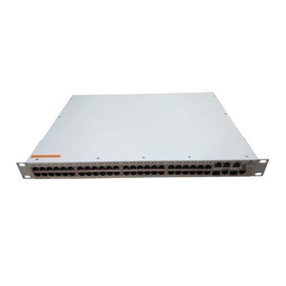
Page 5: Omniswitch 6850 Series
5/5E/6 cabling. OmniSwitch 6850-U24X OmniSwitch 6850-24 Refer to the User Manual CD for additional hardware and software OmniSwitch documentation. OmniSwitch 6850-48 OmniSwitch 6850-24X OmniSwitch 6850-48X OmniSwitch 6850-P24 OmniSwitch 6850-P48 OmniSwitch 6850 Series... -
Page 6: Related Documentation
Related Documentation The following are the titles and descriptions of all the OmniSwitch 6850 Series user documentation included in the User Manual CD: OmniSwitch 6850 Series Getting Started Guide • Describes the hardware and software procedures for getting an OmniSwitch 6850 Series switch up and running. -
Page 7: Installing The Hardware
Installing the Hardware Items Required In addition to the materials and components provided in the OmniSwitch 6850 Series shipment, you must provide the following items in order to complete this installation: Grounding wrist strap • Phillips screwdriver • Serial cable •... -
Page 8: Weight Considerations
All surfaces that are used for intentionally grounding the EUT shall be brought to a bright finish and an anti oxidant solution must be applied to the surfaces being joined. Non-conductive coatings (such as lacquer and enamel) must be removed from threads and other contact surfaces to assure electrical conductivity. -
Page 9: Items Included
Items Included Your OmniSwitch 6850 Series switch order includes the following items: OmniSwitch 6850 Series chassis • Rack mount flanges with attachment screws (rack • mount flanges may be pre-installed on some orders) Power cord (country-specific) • Documentation CD containing a complete set of user •... -
Page 10: Setting Up The Switch
Carefully remove any foam pads and protective plastic from the switch chassis. Note. Alcatel-Lucent provides factory-installed blank cover plates for empty backup power supply or 10-Giga- bit expansion module bays. Do not remove these cover plates unless a backup power supply or expansion module is to be installed immediately at the corresponding bay. -
Page 11: Installation Options
Never obstruct the air vents located at the left and right sides of the chassis. Note. Clearance is not required at the top and bottom of the chassis. For detailed chassis airflow diagrams, refer to the OmniSwitch 6850 Series Hardware Users Guide. Installation Options There are two ways in which the OmniSwitch 6850 Series switches can be installed:... -
Page 12: Rack-Mounting The Switch
(not supplied). Alcatel-Lucent provides two rack-mount flanges with • each OmniSwitch 6850 Series switch. These flanges support standard 19-inch rack mount installations. - Page 13 After the rack-mount flanges are secured to the chas- sis, mark the holes on the rack where the switch is to be installed. Lift and position the switch until the rack-mount flanges are flush with the rack post. Align the holes in the flanges with the rack holes that were marked in step 3.
-
Page 14: Installing Combo Port Sfps
Installing Combo Port SFPs OmniSwitch 6850 Series switches offer Gigabit Ethernet combo ports, located on the front panel. These combo ports support hot-swappable fiber Small Form-Factor Pluggables (SFPs). For instructions on installing and removing combo port SFPs, refer to the instruction card provided with the SFP product. -
Page 15: Connections And Cabling
Connections and Cabling Once your switch is properly set up and all the required hard- ware components are installed, you should connect all network and management cables required for your network applica- tions. Connections may include: RJ-45 cable connection to the console port •... -
Page 16: Booting Omniswitch 6850 Series Switches
Booting OmniSwitch 6850 Series Switches Booting a Standalone Switch The OmniSwitch 6850 Series switch does not use an on/off switch. The power cord is the switch’s only connect/discon- nect device. The power connector socket is located on the switch’s rear panel. For more information, refer to the OmniSwitch 6850 Series Hardware Users Guide. - Page 17 If any of the LED state differs from the states shown in the table above, refer to the OmniSwitch 6850 Series Hardware Users Guide for more information. Contact Alcatel-Lucent Customer Support if the unexpected LED state persists. For information on booting stacked configurations and dynamic slot numbering, refer to the OmniSwitch 6850 Series Hardware Users Guide.
-
Page 18: Your First Login Session
Your First Login Session Once the switch or stack has successfully booted and you have accessed your computer’s terminal emulation software via the console port, you are ready to log in to the switch’s Command Line Interface (CLI) and configure basic information. Complete the following steps during your first login session: Log in to the switch or stack •... -
Page 19: Assigning An Ip Address To The Switch
The default welcome banner, which includes information such as the current software version and system date, displays— followed by the CLI command prompt: Welcome to the Alcatel-Lucent OmniSwitch 6850 Series Software Version 6.1.5.281.R01 Development, March 16, 2007. Copyright(c), 1994-2007 Alcatel-Lucent All Rights reserved. -
Page 20: Unlocking Session Types
Unlocking Session Types Security is a key feature on OmniSwitch 6850 Series switches. As a result, when you access the switch for the first time, you must use a direct console port connection. All other session types (Telnet, FTP, WebView, SNMP, etc.) are “locked out” until they are manually unlocked by the user. -
Page 21: Changing The Login Password
Changing the Login Password Change the login password for admin user sessions by follow- ing the steps below: Be sure that you have logged into the switch as user type admin (see “Logging in to the Switch” on page Enter the keyword password and press Enter. Enter your new password at the prompt (refer to the note below). -
Page 22: Setting The System Time Zone
Setting the System Time Zone The switch’s default time zone is UTC (also referred to as Greenwich Mean Time). If you require a time zone that is specific to your region—or if you need to enable Daylight Savings Time (DST) on the switch—you can configure these settings via the system timezone system daylight savings time... -
Page 23: Specifying A System Name
Specifying a System Name The system name is a simple, user-defined text description for the switch. To specify a system name, enter system name, followed by a text description of up to 19 characters. Note. You cannot include spaces between words when entering a system name. -
Page 24: Files And Directories
Files and Directories Boot and Image Files Although the flash memory on OmniSwitch 6850 Series switches can contain many file types (e.g., log and snapshot files), there are four specific file types that provide key switch and network functions. These files include the boot.cfg file, boot.params file, boot.slot.cfg file, and image (.img) files. -
Page 25: Image Files
If you delete all copies of an image file, you will be required to contact Alcatel-Lucent Customer Support for replacements. Therefore, it is recommended that you keep backup copies on your computer’s hard drive or a locally-accessible server. -
Page 26: Working And Certified Directories
Working and Certified Directories OmniSwitch 6850 Series switches offer flash memory with 8 MB base ROM space and 64 MB extended ROM. This mem- ory is used to store files, including boot and image files, that are used for switch operations. The /flash directory contains two subdirectories: /working and /certified. -
Page 27: Certified Directory
Certified Directory Certified Directory Intended for: Reliable, Tested configuration and image files. The switch will roll back to this software in the event of a system software error. On reload: By default, the switch will use the software in this directory if there are any differences between the Working and Certified directories. -
Page 28: Working And Certified Are Identical
Can I save changes to the Certified directory? No. The /flash/certified directory is intended to store only tested, reliable configuration and image files. Configuration changes must be saved to the boot.cfg file in the /flash/working directory. Once those changes have been road- tested, the contents of the /flash/working directory can be copied to the /flash/certified directory via the copy working certified... -
Page 29: Working And Certified Are Different
Working and Certified Are Different If the software in the /flash/working directory differs even slightly from the software in the /flash/certified directory, the switch will automatically run from the /flash/certified directory. Working Directory revised_boot.cfg K2base.img K2release.img Working and Certified Etc. contents are different. -
Page 30: Using Webview
Using WebView The switch can be configured and monitored using WebView, Alcatel-Lucent’s Web-based device management tool. WebView software is pre-installed in the switch; you are not required to load additional software. Note. Although WebView software is pre-installed, you must first enable HTTP sessions for your switch before you can log in. -
Page 31: Navigating Webview
Enter the switch’s IP address in the browser’s “Address” text field (“Location:” for Netscape users). The login screen displays. Enter the user name and password at the login prompt. Remember, if you have already changed the user name and password for your switch, be sure to use the new information. If you have not changed your user name or password, the factory defaults are admin and switch, respectively. - Page 32 Navigate the application by clicking on the “Configuration Group” buttons in the left-hand toolbar. Main “Configuration Group” Toolbar. (In this case, the group “Health” has been selected.) Using WebView Refine your navigation by selecting “Configuration Options” for each group from the items displayed in the grey, horizontal navigation bar.
-
Page 33: Online Help
Online Help General online help is available through the main Help link located in the top WebView banner. Detailed, context-based help is provided for each status table and configuration dialog window. June 2007 Additional Information For more information on using WebView, refer to the “Using WebView”... -
Page 34: Troubleshooting
Troubleshooting The WebView login screen does not display. This suggests either a physical or network connection issue. Try the following options: Be sure that you have a good physical Ethernet cable • connection to the switch. Be sure your computer has a valid Ethernet connection •...