Table of Contents
Advertisement
Quick Links
Advertisement
Table of Contents

Related Manuals for ZyXEL Communications 760559122614


Summary of Contents for ZyXEL Communications 760559122614
- Page 1 NBG-418N v2 Wireless N300 Home Router Version 1.0 Edition 1, 07/2014 Quick Start Guide User’s Guide Default Login Details LAN IP Address http://192.168.1.1 User Name admin www.zyxel.com Password 1234 Copyright © 2014 ZyXEL Communications Corporation...
- Page 2 IMPORTANT! READ CAREFULLY BEFORE USE. KEEP THIS GUIDE FOR FUTURE REFERENCE. Screenshots and graphics in this book may differ slightly from your product due to differences in your product firmware or your computer operating system. Every effort has been made to ensure that the information in this manual is accurate.
-
Page 3: Table Of Contents
Contents Overview Contents Overview User’s Guide ............................10 Introduction .............................12 The Web Configurator ..........................17 Connection Wizard ..........................20 Modes ..............................29 Tutorials ..............................44 Technical Reference ..........................58 Wireless LAN ............................60 WAN ................................76 LAN .................................92 DHCP Server ............................96 Network Address Translation ........................100 Dynamic DNS ............................109 Firewall .............................. -
Page 4: Table Of Contents
Table of Contents Table of Contents Contents Overview ..........................3 Table of Contents ..........................4 Part I: User’s Guide ..................10 Chapter 1 Introduction............................12 1.1 Overview ............................12 1.2 Securing the NBG-418N v2 .......................13 1.3 LEDs ..............................14 1.4 The WPS/RESET Button ........................14 1.4.1 Using the WPS/RESET Button ....................15 1.5 Wall Mounting ...........................15 Chapter 2 The Web Configurator ........................17... - Page 5 Table of Contents 4.3 Setting your NBG-418N v2 to AP Mode ....................36 4.3.1 Status Screen (AP Mode) ......................37 4.3.2 AP Navigation Panel ........................38 4.4 Setting your NBG-418N v2 to Universal Repeater Mode ..............39 4.4.1 Status Screen (Universal Repeater Mode) ................40 4.4.2 Universal Repeater Navigation Panel ..................42 Chapter 5 Tutorials ...............................44...
- Page 6 Table of Contents 6.9 Scheduling Screen ..........................71 6.10 MBSSID Screen ..........................72 6.11 AP Select Screen ..........................74 Chapter 7 WAN ..............................76 7.1 Overview ............................76 7.2 What You Need To Know ........................76 7.2.1 Configuring Your Internet Connection ..................76 7.3 Internet Connection Screen ......................77 7.3.1 Ethernet Encapsulation ......................77 7.3.2 PPPoE Encapsulation ......................79 7.4 Advanced Screen ..........................81...
- Page 7 Table of Contents 10.6.1 NAT Port Forwarding: Services and Port Numbers .............106 10.6.2 NAT Port Forwarding Example ....................106 10.6.3 Trigger Port Forwarding .......................107 10.6.4 Trigger Port Forwarding Example ..................107 10.6.5 Two Points To Remember About Trigger Ports ..............108 Chapter 11 Dynamic DNS ............................109 11.1 Overview ............................109 11.2 Dynamic DNS Screen...
- Page 8 Table of Contents 15.4 Bandwidth MGMT Screen ......................126 15.5 Advanced Screen .........................127 Chapter 16 System ...............................129 16.1 Overview ............................129 16.2 What You Can Do .........................129 16.3 System General Screen .......................129 16.4 Time Setting Screen ........................130 Chapter 17 Logs ..............................132 17.1 Overview ............................132 17.2 What You Need to Know .......................132 17.3 View Log Screen ...........................132 Chapter 18...
- Page 9 Table of Contents Appendix A IP Addresses and Subnetting..................148 Appendix B Pop-up Windows, JavaScripts and Java Permissions..........158 Appendix C Setting Up Your Computer’s IP Address ..............167 Appendix D Wireless LANs......................195 Appendix E Common Services ......................209 Appendix F Legal Information......................212 Appendix G Customer Support......................218 Index ..............................224 NBG-418N v2 User’s Guide...
-
Page 10: User's Guide
User’s Guide... -
Page 12: Introduction
H A PT ER Introduction 1.1 Overview The NBG-418N v2 extends the range of your existing wired network without additional wiring, providing easy network access to mobile users. Your can create the following connections using the NBG-418N v2: • LAN. You can connect network devices via the Ethernet ports of the NBG-418N v2 so that they can communicate with each other and access the Internet. -
Page 13: Securing The Nbg-418N V2
Chapter 1 Introduction Use a (supported) web browser to manage the NBG-418N v2. Menus vary according to which mode you’re using. Router Mode Non-Router Mode Chapter 4 on page 29 for more information on these modes. 1.2 Securing the NBG-418N v2 Do the following things regularly to make the NBG-418N v2 more secure and to manage the NBG- 418N v2 more effectively. -
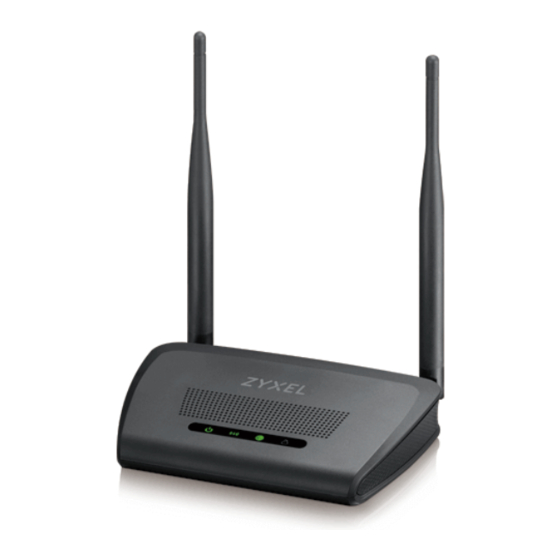
Page 14: Leds
Chapter 1 Introduction 1.3 LEDs Figure 2 Front Panel The following table describes the LEDs and the WPS button. Table 1 Front Panel LEDs and WPS Button COLOR STATUS DESCRIPTION POWER Green The NBG-418N v2 is receiving power and functioning properly. The NBG-418N v2 is not receiving power. -
Page 15: Using The Wps/Reset Button
Chapter 1 Introduction WPS allows you to quickly set up a wireless network with strong security, without having to configure security settings manually. Each WPS connection works between two devices. Both devices must support WPS (check each device’s documentation to make sure). Depending on the devices you have, you can either press a button (recommended) on the device itself, or in its configuration utility or enter a PIN (a unique Personal Identification Number that allows one device to authenticate the other) in each of the two devices. - Page 16 Chapter 1 Introduction Align the holes on the back of the NBG-418N v2 with the screws on the wall. Hang the NBG-418N v2 on the screws. Figure 3 Wall Mounting Example NBG-418N v2 User’s Guide...
-
Page 17: The Web Configurator
H A PT ER The Web Configurator 2.1 Overview This chapter describes how to access the NBG-418N v2 Web Configurator and provides an overview of its screens. The Web Configurator is an HTML-based management interface that allows easy setup and management of the NBG-418N v2 via Internet browser. - Page 18 Chapter 2 The Web Configurator Figure 4 Login Screen Note: The management session automatically times out when the time period set in the Administrator Inactivity Timer field expires (default five minutes). Simply log back into the NBG-418N v2 if this happens. Select the setup type you want to use.
-
Page 19: Resetting The Nbg-418N V2
Chapter 2 The Web Configurator Selecting the setup mode Figure 5 2.3 Resetting the NBG-418N v2 If you forget your password or IP address, or you cannot access the Web Configurator, you will need to use the WPS/RESET button at the back of the NBG-418N v2 to reload the factory-default configuration file. -
Page 20: Connection Wizard
H A PT ER Connection Wizard 3.1 Wizard Setup This chapter provides information on the wizard setup screens in the Web Configurator. The Web Configurator’s wizard setup helps you configure your device to access the Internet. Refer to your ISP (Internet Service Provider) checklist in the Quick Start Guide to know what to enter in each field. -
Page 21: Connection Wizard: Step 1: Wan Connection Type
Chapter 3 Connection Wizard Figure 7 Welcome to the Connection Wizard Read the on-screen information and click Next. 3.2 Connection Wizard: STEP 1: WAN Connection Type The NBG-418N v2 offers three Internet connection types. They are PPP over Ethernet (PPPoE) or Dynamic IP or Static IP. -
Page 22: Pppoe Connection
Chapter 3 Connection Wizard Figure 8 Wizard Step 1: WAN Connection Type: PPPoE, Dynamic IP, Static IP The following table describes the labels in this screen. Table 3 Wizard Step 1: WAN Connection Type LABEL DESCRIPTION PPPoE Select PPPoE radio button for a dial-up connection. Dynamic IP Select Dynamic IP radio button if your ISP did not assign you a fixed IP address. -
Page 23: Dynamic Ip Connection
Chapter 3 Connection Wizard By implementing PPPoE directly on the NBG-418N v2 (rather than individual computers), the computers on the LAN do not need PPPoE software installed, since the NBG-418N v2 does that part of the task. Furthermore, with NAT, all of the LAN's computers will have Internet access. Figure 9 Wizard Step 2: PPPoE Connection The following table describes the labels in this screen. -
Page 24: Static Ip Connection
Chapter 3 Connection Wizard Figure 10 Wizard Step 1: Dynamic IP Connection 3.2.3 Static IP Connection The following wizard screen allows you to assign a fixed IP address to the NBG-418N v2 Figure 11 Wizard Step 2: Static IP Click Next to open the following screen. NBG-418N v2 User’s Guide... -
Page 25: Connection Wizard: Step 2: Wireless Lan
Chapter 3 Connection Wizard Figure 12 Wizard Step 2: Static IP Connection The following table describes the labels in this screen Table 5 Wizard Step 2: Static IP Connection LABEL DESCRIPTION IP Address Select this option if you were given IP address and/or DNS server settings by the ISP. - Page 26 Chapter 3 Connection Wizard Figure 13 Wizard Step 2: Wireless LAN The following table describes the labels in this screen. Table 6 Wizard Step 2: Wireless LAN LABEL DESCRIPTION Wireless LAN Disable the Click this check box to disable the WLAN in the NBG-418N v2. wireless radio SSID Enter a descriptive name (up to 32 printable 7-bit ASCII characters) for the wireless LAN.
-
Page 27: Connection Wizard: Step 3: Internet Configuration
Chapter 3 Connection Wizard Table 6 Wizard Step 2: Wireless LAN (continued) LABEL DESCRIPTION WPA2-PSK AES Choose WPA2-PSK AES security to configure a Pre-Shared Key. Choose this option only if your wireless clients support WPA2-PSK. You will need to enter a Pre-Shared Key in the box below. - Page 28 Chapter 3 Connection Wizard Figure 15 Connection Wizard Complete Well done! You have successfully set up your NBG-418N v2 to operate on your network and access the Internet. NBG-418N v2 User’s Guide...
-
Page 29: Modes
H A PT ER Modes 4.1 Overview You can set up the NBG-418N v2 with other IEEE 802.11b/g/n compatible devices in different device modes. Note: Choose your device mode carefully to avoid having to change it later. The NBG- 418N v2 automatically restarts when you change modes. The default LAN IP address of the NBG-418N v2 in Router mode is 192.168.1.1. -
Page 30: Setting Your Nbg-418N V2 To Router Mode
Chapter 4 Modes • Universal Repeater: In this mode, the NBG-418N v2 (N) can be an access point and a wireless client at the same time. Use this mode if there is an existing wireless router or access point in your network and you want the NBG-418N v2 (N) to wirelessly relay communications from its wireless clients to the access point. -
Page 31: Status Screen (Router Mode)
Chapter 4 Modes A pop-up window appears providing information on this mode. Click OK in the pop-up message window. Click Apply. Note: Wait while the NBG-418N v2 restarts, then log in to the Web Configurator again. The NBG-418N v2 IP address is now 192.168.1.1. 4.2.1 Status Screen (Router Mode) The screen below shows the status screen in Router mode. - Page 32 Chapter 4 Modes The following table describes the labels shown in the Status screen in Router mode. Table 8 Web Configurator Status Screen (Router Mode) LABEL DESCRIPTION Device Information System Name This is the System Name you enter in the Maintenance > System > General screen.
- Page 33 Chapter 4 Modes Table 8 Web Configurator Status Screen (Router Mode) (continued) LABEL DESCRIPTION Link-Local Address This field displays the link-local IP address of the NBG-418N v2 LAN port. A link-local address is similar to a “private IP address” in IPv4. You can have the same link-local address on multiple interfaces on a device.
- Page 34 Chapter 4 Modes The following table describes the labels in this screen. Table 9 Summary: DHCP Table LABEL DESCRIPTION This is the index number of the host computer. IP Address This field displays the IP address relative to the # field listed above. Host Name This field displays the computer host name.
-
Page 35: Router Mode Navigation Panel
Chapter 4 Modes Table 10 Summary: Packet Statistics (continued) LABEL DESCRIPTION Set Interval Click this button to apply the new poll interval you entered in the Poll Interval(s) field. Stop Click Stop to stop refreshing statistics. 4.2.2 Router Mode Navigation Panel Use the menu in the navigation panel menus to configure NBG-418N v2 features in Router Mode. -
Page 36: Setting Your Nbg-418N V2 To Ap Mode
Chapter 4 Modes Table 11 Menus: Router Mode (continued) LINK FUNCTION Internet This screen allows you to configure ISP parameters, WAN IP address Connection assignment, DNS servers and the WAN MAC address. Advanced Use this screen to configure multicast WAN and auto IP setup. IPv6 Use this screen to set the IPv6 WAN connection type. -
Page 37: Status Screen (Ap Mode)
Chapter 4 Modes The default LAN IP address of the NBG-418N v2 is 192.168.1.1 in router mode (192.168.1.2 by default in non-router mode). In router mode, the NBG-418N v2 can assign your computer an IP address, so you must set your computer to get an IP address automatically (computer factory default) or give it a fixed IP address in the range between 192.168.1.3 and 192.168.1.254. -
Page 38: Ap Navigation Panel
Chapter 4 Modes The following table describes the labels shown in the Status screen. Table 12 Status Screen (AP Mode) LABEL DESCRIPTION Device Information System Name This is the System Name you enter in the Maintenance > System > General screen. -
Page 39: Setting Your Nbg-418N V2 To Universal Repeater Mode
Chapter 4 Modes Figure 26 Menu: AP Mode The following table describes the sub-menus. Table 13 Menu: AP Mode LINK FUNCTION Network Wireless LAN General Use this screen to configure wireless LAN. MAC Filter Use the MAC filter screen to configure the NBG-418N v2 to block access to devices or block the devices from accessing the NBG-418N v2. -
Page 40: Status Screen (Universal Repeater Mode)
Chapter 4 Modes The default LAN IP address of the NBG-418N v2 is 192.168.1.1 in router mode (192.168.1.2 by default in non-router mode). In router mode, the NBG-418N v2 can assign your computer an IP address, so you must set your computer to get an IP address automatically (computer factory default) or give it a fixed IP address in the range between 192.168.1.3 and 192.168.1.254. - Page 41 Chapter 4 Modes Figure 28 Status Screen (Universal Repeater Mode) The following table describes the labels shown in the Status screen. Table 14 Status Screen (Universal Repeater Mode) LABEL DESCRIPTION Device Information System Name This is the System Name you enter in the Maintenance > System > General screen.
-
Page 42: Universal Repeater Navigation Panel
Chapter 4 Modes Table 14 Status Screen (Universal Repeater Mode) (continued) LABEL DESCRIPTION - WPS This shows the WPS (WiFi Protected Setup) Status. Click the link to display Network > Wireless LAN > WPS screen. WLAN STA Information - SSID This is the name of the selected AP that the NBG-418N v2 is associating with. - Page 43 Chapter 4 Modes The following table describes the sub-menus. Table 15 Menu: Universal Repeater Mode LINK FUNCTION Status This screen shows the NBG-418N v2’s general device, system and interface status information. Use this screen to access the wizard, and summary statistics tables. Network WLAN AP Select...
-
Page 44: Tutorials
H A PT ER Tutorials 5.1 Overview This chapter provides tutorials for your NBG-418N v2 as follows: • How to Connect to the Internet from an AP • Configure Wireless Security Using WPS on both your NBG-418N v2 and Wireless Client •... -
Page 45: Push Button Configuration (Pbc)
Chapter 5 Tutorials • Push Button Configuration (PBC) - create a secure wireless network simply by pressing a button. See Section 5.3.1 on page 45.This is the easier method. • PIN Configuration - create a secure wireless network simply by entering a wireless client's PIN (Personal Identification Number) in the NBG-418N v2’s interface. -
Page 46: Pin Configuration
Chapter 5 Tutorials Figure 31 Example WPS Process: PBC Method NBG-418N v2 Wireless Client WPS/Reset WITHIN 2 MINUTES SECURITY INFO COMMUNICATION 5.3.2 PIN Configuration When you use the PIN configuration method, you need to use both NBG-418N v2’s configuration interface and the client’s utilities. Launch your wireless client’s configuration utility. - Page 47 Chapter 5 Tutorials Figure 32 Example WPS Process: PIN Method Wireless Client NBG-418N v2 WITHIN 2 MINUTES Authentication by PIN SECURITY INFO COMMUNICATION NBG-418N v2 User’s Guide...
-
Page 48: Enable And Configure Wireless Security Without Wps On Your Nbg-418N V2
Chapter 5 Tutorials 5.4 Enable and Configure Wireless Security without WPS on your NBG-418N v2 This example shows you how to configure wireless security settings with the following parameters on your NBG-418N v2. SSID SSID_Example3 Channel Security WPA-PSK (Pre-Shared Key: ThisismyWPA-PSKpre-sharedkey) Follow the steps below to configure the wireless settings on your NBG-418N v2. -
Page 49: Configure Your Wireless Client
Chapter 5 Tutorials Figure 34 Tutorial: Status Screen 5.4.1 Configure Your Wireless Client Note: We use the ZyXEL M-302 wireless adapter utility screens as an example for the wireless client. The screens may vary for different models. The NBG-418N v2 supports IEEE 802.11b, IEEE 802.11g and IEEE 802.11n wireless clients. Make sure that your notebook or computer’s wireless adapter supports one of these standards. - Page 50 Chapter 5 Tutorials Figure 35 Connecting a Wireless Client to a Wireless Network t Select WPA2-PSK and type the security key in the following screen. Click Next. Figure 36 Security Settings The Confirm Save window appears. Check your settings and click Save to continue. Figure 37 Confirm Save Check the status of your wireless connection in the screen below.
-
Page 51: Using Multiple Ssids On The Nbg-418N V2
Chapter 5 Tutorials Figure 38 Link Status If your connection is successful, open your Internet browser and enter http://www.zyxel.com or the URL of any other web site in the address bar. If you are able to access the web site, your wireless connection is successfully configured. -
Page 52: Configuring Security Settings Of Multiple Ssids
Chapter 5 Tutorials For example, you may set up three wireless networks (A, B and C) in your office. A is for workers, B is for guests and C is specific to a VoIP device in the meeting room. SSID_Workers SSID_VoIP SSID_Guest 5.5.1 Configuring Security Settings of Multiple SSIDs... - Page 53 Chapter 5 Tutorials Type a new password and retype it to confirm, then click Apply. Otherwise, click Ignore. A window appears asking you to select Wizard or Advance mode. Click Go to Advanced Setup in the navigation panel. Go to Network > Wireless LAN > MBSSID. Type SSID_Workers in the Name (SSID) field, select WPA2-PSK(AES) in the Security drop-down list, enter the pre-share key and click Apply.
- Page 54 Chapter 5 Tutorials 11 Click the MAC Filter tab to configure MAC filtering for the SSID_VoIP wireless network. Go to Network > Wireless LAN > MAC Filter and click Active check box and enter a MAC address of the VoIP device in the MAC Address field. Click Add to save the MAC address in the white list table.
-
Page 55: Installing Upnp In Windows 7 Example
Chapter 5 Tutorials 5.6 Installing UPnP in Windows 7 Example For more information on how to install Universal Plug and Play in Windows on your computer, see Section 14.4 on page 119 5.7 Using Bandwidth Management on the NBG-418N v2 Bandwidth management provides a convenient way to manage the use of various services on the network. - Page 56 Chapter 5 Tutorials Figure 39 Bandwidth Management Example -> VoIP -> FTP -> HTTP -> Chat, E-mail You can allocate specific amounts of bandwidth capacity (bandwidth budgets) to individual applications (like VoIP, Web, FTP, and E-mail for example). This example shows you how to configure the Bandwidth Management with the following parameters on your NBG-418N v2 (in router mode).
- Page 57 Chapter 5 Tutorials Then, Click Add in the QoS Rules section and several fields appears. Enter 192.168.1.10 in the Source IP field, 192.168.1.10/32 will appear in the field, the 32-bits network is IPv4 addresses block that is assigned by your ISP. Next, enter 150000 for Up Ceiling and 600000 for Down Ceiling and click Add.
-
Page 58: Technical Reference
Technical Reference... -
Page 60: Wireless Lan
H A PT ER Wireless LAN 6.1 Overview This chapter discusses how to configure the wireless network settings in your NBG-418N v2. See the appendices for more detailed information about wireless networks. The following figure provides an example of a wireless network. Figure 40 Example of a Wireless Network The wireless network is the part in the blue circle. -
Page 61: What You Can Do
Chapter 6 Wireless LAN 6.2 What You Can Do Wireless screens vary according to the device mode you are using. Wireless Screen Router Access Point Universal Repeater General MAC Filter Advanced ... -
Page 62: Wireless Security Overview
Chapter 6 Wireless LAN • If two wireless networks overlap, they should use different channels. Like radio stations or television channels, each wireless network uses a specific channel, or frequency, to send and receive information. • Every wireless client in the same wireless network must use security compatible with the AP. Security stops unauthorized devices from using the wireless network. -
Page 63: Encryption
Chapter 6 Wireless LAN 6.3.4 Encryption Wireless networks can use encryption to protect the information that is sent in the wireless network. Encryption is like a secret code. If you do not know the secret code, you cannot understand the message. Table 16 Types of Encryption for Each Type of Authentication NO AUTHENTICATION Weakest... - Page 64 Chapter 6 Wireless LAN Note: If you are configuring the NBG-418N v2 from a computer connected to the wireless LAN and you change the NBG-418N v2’s SSID, channel or security settings, you will lose your wireless connection when you press Apply to confirm. You must then change the wireless settings of your computer to match the NBG-418N v2’s new settings.
-
Page 65: No Security
Chapter 6 Wireless LAN The following table describes the general wireless LAN labels in this screen. Table 17 Network > Wireless LAN > General LABEL DESCRIPTION WLAN STA This section is available only when the NBG-418N v2 is in universal repeater mode. This Information shows the wireless and security settings of the selected AP wireless network. -
Page 66: Wep Encryption
Chapter 6 Wireless LAN Note: If you do not enable any wireless security on your NBG-418N v2, your network is accessible to any wireless networking device that is within range. Figure 43 Network > Wireless LAN > General: No Security The following table describes the labels in this screen. -
Page 67: Wpa-Psk/Wpa2-Psk
Chapter 6 Wireless LAN The following table describes the wireless LAN security labels in this screen. Table 19 Network > Wireless LAN > General: Static WEP LABEL DESCRIPTION Security Mode Choose Static WEP from the drop-down list box. WEP Encryption Select 64-bit WEP or 128-bit WEP to enable data encryption. -
Page 68: Mac Filter
Chapter 6 Wireless LAN Table 20 Network > Wireless LAN > General: WPA-PSK/WPA2-PSK (continued) LABEL DESCRIPTION Cipher Type Select the encryption type (TKIP, AES or TKIP+AES) for data encryption. Select AES if your wireless clients can all use AES. Otherwise, select TKIP or select TKIP+AES to allow the wireless clients to use either TKIP or AES Pre-Shared Key WPA-PSK/WPA2-PSK uses a simple common password for authentication. -
Page 69: Wireless Lan Advanced Screen
Chapter 6 Wireless LAN The following table describes the labels in this menu. Table 21 Network > Wireless LAN > MAC Filter LABEL DESCRIPTION Active Click Active check box to enable MAC address filtering. MAC Address This field shows the MAC addresses of the wireless station that are allowed or denied access (White List) to the NBG-418N v2 in these address fields. -
Page 70: Wps Screen
Chapter 6 Wireless LAN Table 22 Network > Wireless LAN > Advanced (Universal Repeater Mode) LABEL DESCRIPTION Enable Intra-BSS A Basic Service Set (BSS) exists when all communications between wireless clients or Traffic between a wireless client and a wired network client go through one access point (AP). Intra-BSS traffic is traffic between wireless clients in the BSS. -
Page 71: Wps Station Screen
Chapter 6 Wireless LAN Table 23 Network > Wireless LAN > WPS (continued) LABEL DESCRIPTION Apply Click Apply to save your changes back to the NBG-418N v2. Refresh Click Refresh to get this screen information afresh. 6.8 WPS Station Screen Use this screen when you want to add a wireless station using WPS. -
Page 72: Mbssid Screen
Chapter 6 Wireless LAN Figure 50 Network > Wireless LAN > Scheduling The following table describes the labels in this screen. Table 25 Network > Wireless LAN > Scheduling LABEL DESCRIPTION Enable Wireless Select this to enable Wireless LAN scheduling. LAN Scheduling Action Select On or Off to specify whether the Wireless LAN is turned on or off. - Page 73 Chapter 6 Wireless LAN Figure 51 Network > Wireless LAN > MBSSID The following table describes the labels in this screen. Table 26 Network > Wireless LAN > MBSSID LABEL DESCRIPTION Network Profiles Select Click the Select radio button to select the Multiple Basic Service Set Identifier (MBSSID) you wish to edit.
-
Page 74: Ap Select Screen
Chapter 6 Wireless LAN Table 26 Network > Wireless LAN > MBSSID LABEL DESCRIPTION Apply Click Apply to save your changes back to the NBG-418N v2. Reset Click Reset to reload the previous configuration for this screen. 6.11 AP Select Screen Use this screen to choose an access point that you want the NBG-418N v2 in universal repeater mode) to connect to. - Page 75 Chapter 6 Wireless LAN Table 27 Network > Wireless LAN > AP Select (continued) LABEL DESCRIPTION Mode This displays which IEEE 802.11b/g/n wireless networking standards the wireless device supports. Security Mode This displays the type of security configured on the wireless device. OPEN means no security is configured and you can connect to it without a password.
-
Page 76: Wan
H A PT ER 7.1 Overview This chapter discusses the NBG-418N v2’s WAN screens. Use these screens to configure your NBG- 418N v2 for Internet access. A WAN (Wide Area Network) connection is an outside connection to another network or the Internet. -
Page 77: Internet Connection Screen
Chapter 7 WAN WAN IP Address The WAN IP address is an IP address for the NBG-418N v2, which makes it accessible from an outside network. It is used by the NBG-418N v2 to communicate with other devices in other networks. - Page 78 Chapter 7 WAN Figure 54 Network > WAN > Internet Connection: Ethernet Encapsulation The following table describes the labels in this screen. Table 28 Network > WAN > Internet Connection: Ethernet Encapsulation LABEL DESCRIPTION ISP Parameters for Internet Access (Ethernet Static) Connection Type Choose the Ethernet (Static) option when the WAN port is used as a regular Ethernet.
-
Page 79: Pppoe Encapsulation
Chapter 7 WAN Table 28 Network > WAN > Internet Connection: Ethernet Encapsulation (continued) LABEL DESCRIPTION First DNS Server Enter the first and second DNS server's IP address in the fields. Second DNS Server WAN MAC Address The MAC address section allows users to configure the WAN port's MAC address by either using the NBG-418N v2’s MAC address, copying the MAC address from a computer on your LAN or manually entering a MAC address. - Page 80 Chapter 7 WAN For the service provider, PPPoE offers an access and authentication method that works with existing access control systems (for example Radius). One of the benefits of PPPoE is the ability to let you access one of multiple network services, a function known as dynamic service selection.
-
Page 81: Advanced Screen
Chapter 7 WAN Table 29 Network > WAN > Internet Connection: PPPoE Encapsulation (continued) LABEL DESCRIPTION MTU Size Enter the MTU or the largest packet size per frame that your NBG-418N v2 can receive and process. Connection Type Select Continuous if you do not want the connection to time out. Select Connection on Demand if you want to connect for a certain amount of time before the router automatically disconnects from the PPPoE server. -
Page 82: Ipv6 Screen
Chapter 7 WAN The following table describes the labels in this screen. Table 30 Network > WAN > Advanced LABEL DESCRIPTION Multicast Setup Multicast Proxy Click the Multicast Proxy radio button to enable this function on the NBG-418N v2. This allows an IPv6 router to discover the presence of MLD hosts who wish to receive multicast packets and the IP address of multicast groups the hosts want to join on its network. - Page 83 Chapter 7 WAN Figure 58 Network > WAN > IPv6 (Static IPv6) The following table describes the labels in this screen. Table 32 Network > WAN > IPv6 (Static IPv6) LABEL DESCRIPTION IPv6 Connection Select Static IPv6 when your ISP provides you a set IPv6 address that does not Type change.
- Page 84 Chapter 7 WAN Table 32 Network > WAN > IPv6 (continued)(Static IPv6) LABEL DESCRIPTION Address Autoconfiguration Settings Enable Click Enable Autoconfiguration if you want the devices on your local area network to Autoconfiguration obtain network address that are not managed by a DHCPv6 server. Autoconfiguration Select SLAAC + Stateless DHCPv6 if you want the interface to automatically generate Type...
- Page 85 Chapter 7 WAN Table 33 Network > WAN > IPv6 (continued)(SLAAC/DHCPv6) LABEL DESCRIPTION Use the following Click Use the following DNS address radio button to use a fixed DNS address. DNS address Primary and Enter the Primary and Secondary DNS address for the IPv6 server in the appropriate Secondary DNS box fields.
- Page 86 Chapter 7 WAN Figure 60 Network > WAN > IPv6 (PPPoE) The following table describes the labels in this screen. Table 34 Network > WAN > IPv6 (PPPoE) LABEL DESCRIPTION IPv6 Connection Select PPPoE if your ISP requires your to use a PPPoE connection to IPv6 Internet. This Type method of connection typically requires you to enter a Username and Password (provided by your ISP) to gain access to the IPv6 Internet.
- Page 87 Chapter 7 WAN Table 34 Network > WAN > IPv6 (continued)(PPPoE) LABEL DESCRIPTION Connection Type Select Continuous if you do not want the connection to time out. Select Connection on Demand if you want to connect for a certain amount of time before the router automatically disconnects from the PPPoE server.
- Page 88 Chapter 7 WAN Figure 61 Network > WAN > IPv6 (IPv6 in IPv4 Tunnel) The following table describes the labels in this screen. Table 35 Network > WAN > IPv6 (IPv6 in IPv4 Tunnel) LABEL DESCRIPTION IPv6 Connection IPv6 in IPv4 Tunnel is the encapsulation of IPv6 packets in IPv4 packets so that IPv6 Type packets can be sent over an IPv4 infrastructure.
- Page 89 Chapter 7 WAN Table 35 Network > WAN > IPv6 (IPv6 in IPv4 Tunnel) LABEL DESCRIPTION Address Autoconfiguration Settings Enable Click Enable Autoconfiguration if you want the devices on your local area network to Autoconfiguration obtain network address that are not managed by a DHCPv6 server. Autoconfiguration Select SLAAC + Stateless DHCPv6 if you want the interface to automatically generate Type...
- Page 90 Chapter 7 WAN Table 36 Network > WAN > IPv6 (continued)(6 to 4) LABEL DESCRIPTION IPv6 DNS Settings Primary/Secondary Enter the Primary and Secondary DNS address for the IPv6 server in the appropriate DNS Address box fields. Lan IPv6 Address Settings LAN IPv6 Address Enter the IPv6 IP address for the LAN port in this field.
- Page 91 Chapter 7 WAN The following table describes the labels in this screen. Table 37 Network > WAN > IPv6 (6rd) LABEL DESCRIPTION IPv6 Connection IPv6 Rapid Deployment (6rd) is used when the local network uses IPv6 and the ISP has Type an IPv4 network.
-
Page 92: Lan
H A PT ER 8.1 Overview This chapter describes how to configure LAN settings. A Local Area Network (LAN) is a shared communication system to which many computers are attached. A LAN is a computer network limited to the immediate area, usually the same building or floor of a building. -
Page 93: Ip Address And Subnet Mask
Chapter 8 LAN Figure 65 LAN and WAN IP Addresses The LAN parameters of the NBG-418N v2 are preset in the factory with the following values: • IP address of 192.168.1.1 with subnet mask of 255.255.255.0 (24 bits) • DHCP server enabled with 32 client IP addresses starting from 192.168.1.33. These parameters should work for the majority of installations. -
Page 94: Ip Pool Setup
Chapter 8 LAN important because without it, you must know the IP address of a computer before you can access The NBG-418N v2 can get the DNS server addresses in the following ways. The ISP tells you the DNS server addresses, usually in the form of an information sheet, when you sign up. - Page 95 Chapter 8 LAN Table 38 Network > LAN > IP (continued) LABEL DESCRIPTION IP Subnet Mask The subnet mask specifies the network number portion of an IP address. Your NBG- 418N v2 will automatically calculate the subnet mask based on the IP address that you assign.
-
Page 96: Dhcp Server
H A PT ER DHCP Server 9.1 Overview DHCP (Dynamic Host Configuration Protocol, RFC 2131 and RFC 2132) allows individual clients to obtain TCP/IP configuration at start-up from a server. You can configure the NBG-418N v2’s LAN as a DHCP server or disable it. When configured as a server, the NBG-418N v2 provides the TCP/IP configuration for the clients. -
Page 97: Advanced Screen
Chapter 9 DHCP Server Figure 67 Network > DHCP Server > General The following table describes the labels in this screen. Table 39 Network > DHCP Server > General LABEL DESCRIPTION DHCP Mode Select DHCP server from the drop-down list to have the NBG-418N v2 act as a DHCP server. -
Page 98: Client List Screen
Chapter 9 DHCP Server Figure 68 Network > DHCP Server > Advanced The following table describes the labels in this screen. Table 40 Network > DHCP Server > Advanced LABEL DESCRIPTION Static DHCP Table IP Address Type the LAN IP address of a computer on your LAN. MAC Address Type the MAC address (with colons) of a computer on your LAN. - Page 99 Chapter 9 DHCP Server Figure 69 Network > DHCP Server > Client List The following table describes the labels in this screen. Table 41 Network > DHCP Server > Client List LABEL DESCRIPTION Host Name This field displays the computer Host name. IP Address This field displays the IP address of the computers on the LAN port.
-
Page 100: Network Address Translation
HAPTER Network Address Translation 10.1 Overview This chapter discusses how to configure NAT on the NBG-418N v2. NAT (Network Address Translation - NAT, RFC 1631) is the translation of the IP address of a host in a packet. For example, the source address of an outgoing packet, used within one network is changed to a different IP address known within another network. -
Page 101: What You Can Do
Chapter 10 Network Address Translation 10.2 What You Can Do • Use the General screen to enable NAT and set a default server (Section 10.3 on page 102). • Use the Application screen to change your NBG-418N v2’s port forwarding settings (Section 10.4 on page 103). -
Page 102: General Nat Screen
Chapter 10 Network Address Translation The global IP addresses for the inside hosts can be either static or dynamically assigned by the ISP. In addition, you can designate servers, for example, a web server and a telnet server, on your local network and make them accessible to the outside world. -
Page 103: Nat Application Screen
Chapter 10 Network Address Translation The following table describes the labels in this screen. Table 43 Network > NAT > General LABEL DESCRIPTION NAT Setup Network Address Network Address Translation (NAT) allows the translation of an Internet protocol Translation address used within one network (for example a private IP address used in a local network) to a different IP address known within another network (for example a public IP address used on the Internet). - Page 104 Chapter 10 Network Address Translation Network > NAT > Application Figure 73 The following table describes the labels in this screen. Table 44 Network > NAT > Application LABEL DESCRIPTION Add Application Rule User Name Select an option from the drop-down list to choose a pre-defined service. The pre- defined service port number(s) and protocol will display in the fields below.
-
Page 105: Port Triggering Screen
Chapter 10 Network Address Translation 10.5 Port Triggering Screen To change your NBG-418N v2’s port trigger settings, click Network > NAT > Port Triggering. The screen appears as shown. Note: Only one LAN computer can use a port trigger (range) at a time. Figure 74 Network >... -
Page 106: Technical Reference
Chapter 10 Network Address Translation Table 45 Network > NAT > Port Triggering (continued) LABEL DESCRIPTION Start Related Type a Starting port number that is related to the open protocol. Port End Related Type a Ending port number that is related to the open protocol. Port Open Protocol The open protocol is the protocol (UDP, TCP or UDP/TCP) that causes (or triggers) the... -
Page 107: Trigger Port Forwarding
Chapter 10 Network Address Translation Figure 75 Multiple Servers Behind NAT Example 10.6.3 Trigger Port Forwarding Some services use a dedicated range of ports on the client side and a dedicated range of ports on the server side. With regular port forwarding you set a forwarding port in NAT to forward a service (coming in from the server on the WAN) to the IP address of a computer on the client side (LAN). -
Page 108: Two Points To Remember About Trigger Ports
Chapter 10 Network Address Translation Port 7070 is a “trigger” port and causes the NBG-418N v2 to record Jane’s computer IP address. The NBG-418N v2 associates Jane's computer IP address with the "incoming" port range of 6970- 7170. The Real Audio server responds using a port number ranging between 6970-7170. The NBG-418N v2 forwards the traffic to Jane’s computer IP address. -
Page 109: Dynamic Dns
HAPTER Dynamic DNS 11.1 Overview Dynamic Domain Name Service (DDNS) services let you use a fixed domain name with a dynamic IP address. Users can always use the same domain name instead of a different dynamic IP address that changes each time to connect to the NBG-418N v2 or a server in your network. Note: The NBG-418N v2 must have a public global IP address and you should have your registered DDNS account information on hand. - Page 110 Chapter 11 Dynamic DNS Table 46 Network > DDNS LABEL DESCRIPTION Apply Click Apply to save your changes back to the NBG-418N v2. Reset Click Reset to begin configuring this screen afresh. Dynamic DDNS Table Select Click the Select check box to select the DDNS entry and click Delete to remove it or Apply to save changes made to it.
-
Page 111: Firewall
HAPTER Firewall 12.1 Overview Use these screens to enable and configure the firewall that protects your NBG-418N v2 and your LAN from unwanted or malicious traffic. Enable the firewall to protect your LAN computers from attacks by hackers on the Internet and control access between the LAN and WAN. -
Page 112: What You Need To Know
Chapter 12 Firewall 12.3 What You Need To Know The NBG-418N v2’s firewall feature physically separates the LAN and the WAN and acts as a secure gateway for all data passing between the networks. 12.3.1 About the NBG-418N v2 Firewall The NBG-418N v2 firewall is a stateful inspection firewall and is designed to protect against Denial of Service attacks when activated (click the General tab under Firewall and then click the Enable Firewall check box). -
Page 113: Services Screen
Chapter 12 Firewall Figure 79 Security > Firewall > General The following table describes the labels in this screen. Table 47 Security > Firewall > General LABEL DESCRIPTION Enable Firewall Select the Enable Firewall check box to activate the firewall. The NBG-418N v2 performs access control and protects against Denial of Service (DoS) attacks when the firewall is activated. - Page 114 Chapter 12 Firewall Table 48 Security > Firewall > Services (continued) LABEL DESCRIPTION VPN Passthrough Select the checkbox to enable the advanced pass through features: • PPTP Passthrough: Select this option to allow the NBG-418N v2 to pass through VPN traffic using PPTP. •...
-
Page 115: Remote Management
HAPTER Remote Management 13.1 Overview This chapter provides information on the Remote Management screens. Remote management allows you to determine which services/protocols can access which NBG- 418N v2 interface (if any) from which computers. You may manage your NBG-418N v2 from a remote location via: •... -
Page 116: Remote Management Limitations
Chapter 13 Remote Management 13.1.1 Remote Management Limitations Remote management over LAN or WAN will not work when: You have disabled that service in one of the remote management screens. The IP address in the Secured Client WAN IP Address field does not match the client IP address. If it does not match, the NBG-418N v2 will disconnect the session immediately. - Page 117 Chapter 13 Remote Management The following table describes the labels in this screen. Table 49 Management > Remote MGMT > WWW LABEL DESCRIPTION Enable WWW Click the Enable WWW check box to configure your NBG-418N v2 via HTTP using a web browser. Server Port You may change the Server port number for a service if needed, however you must use the same port number in order to use that service for remote...
-
Page 118: Universal Plug-And-Play (Upnp)
HAPTER Universal Plug-and-Play (UPnP) 14.1 Overview This chapter introduces the UPnP feature in the Web Configurator. Universal Plug and Play (UPnP) is a distributed, open networking standard that uses TCP/IP for simple peer-to-peer network connectivity between devices. A UPnP device can dynamically join a network, obtain an IP address, convey its capabilities and learn about other devices on the network. -
Page 119: Configuring Upnp
Chapter 14 Universal Plug-and-Play (UPnP) All UPnP-enabled devices may communicate freely with each other without additional configuration. Disable UPnP if this is not your intention. 14.3 Configuring UPnP Use this screen to enable UPnP. Click the Management > UPnP to open the following screen. Figure 82 Management >... - Page 120 Chapter 14 Universal Plug-and-Play (UPnP) Click Change Advanced Sharing Settings. Under Network Discover section, select Turn on network discovery and click Save Changes. Network discovery allows your computer to find other computers and devices on the network and other computers on the network to find your computer. This makes it easier to share files and printers.
-
Page 121: Using Upnp In Windows Xp Example
Chapter 14 Universal Plug-and-Play (UPnP) 14.4.1 Using UPnP in Windows XP Example This section shows you how to use the UPnP feature in Windows XP. You must already have UPnP installed in Windows XP and UPnP activated on the NBG-418N v2. Make sure the computer is connected to a LAN port of the NBG-418N v2. - Page 122 Chapter 14 Universal Plug-and-Play (UPnP) Figure 84 Internet Connection Properties You may edit or delete the port mappings or click Add to manually add port mappings. Figure 85 Internet Connection Properties: Advanced Settings Figure 86 Internet Connection Properties: Advanced Settings: Add Note: When the UPnP-enabled device is disconnected from your computer, all port mappings will be deleted automatically.
-
Page 123: Web Configurator Easy Access
Chapter 14 Universal Plug-and-Play (UPnP) Figure 87 System Tray Icon Double-click on the icon to display your current Internet connection status. Figure 88 Internet Connection Status 14.4.2 Web Configurator Easy Access With UPnP, you can access the web-based configurator on the NBG-418N v2 without finding out the IP address of the NBG-418N v2 first. - Page 124 Chapter 14 Universal Plug-and-Play (UPnP) Figure 89 Network Connections An icon with the description for each UPnP-enabled device displays under Local Network. Right-click on the icon for your NBG-418N v2 and select Invoke. The Web Configurator login screen displays. Figure 90 Network Connections: My Network Places Right-click on the icon for your NBG-418N v2 and select Properties.
- Page 125 Chapter 14 Universal Plug-and-Play (UPnP) Figure 91 Network Connections: My Network Places: Properties: Example NBG-418N v2 User’s Guide...
-
Page 126: Bandwidth Mgmt
HAPTER Bandwidth MGMT 15.1 Overview Bandwidth management provides a convenient way to manage the use of various services on the network. It manages general protocols (for example, HTTP and FTP) and applies traffic prioritization to enhance the performance of delay-sensitive applications like voice and video. 15.2 What You Can Do •... -
Page 127: Advanced Screen
Chapter 15 Bandwidth MGMT The following table describes the labels in this screen. Table 51 Management > Bandwidth MGMT > Bandwidth MGMT LABEL DESCRIPTION Service Management Enable Bandwidth Click the Enable Bandwidth Management check box to activate the bandwidth Management management feature in the NBG-418N v2. - Page 128 Chapter 15 Bandwidth MGMT Table 52 Management > Bandwidth MGMT > Advanced (continued) LABEL DESCRIPTION Click Add button to add the QoS rule. Delete Click Delete to remove the QoS rule. NBG-418N v2 User’s Guide...
-
Page 129: System
HAPTER System 16.1 Overview This chapter provides information on the System screens. See the chapter about wizard setup for more information on the next few screens. 16.2 What You Can Do • Use the General screen to enter a name to identify the NBG-418N v2 in the network and set the password (Section 16.3 on page 129). -
Page 130: Time Setting Screen
Chapter 16 System The following table describes the labels in this screen. Table 53 Maintenance > System > General LABEL DESCRIPTION System Setup System Name System Name is a unique name to identify the NBG-418N v2 in an Ethernet network. It is recommended you enter your computer’s “Computer name”... - Page 131 Chapter 16 System The following table describes the labels in this screen. Table 54 Maintenance > System > Time Setting LABEL DESCRIPTION Current Time and Date Current Time This field displays the time of your NBG-418N v2. Each time you reload this page, the NBG-418N v2 synchronizes the time with the time server.
-
Page 132: Logs
HAPTER Logs 17.1 Overview This chapter contains information about configuring general log settings and viewing the NBG-418N v2’s logs. The Web Configurator allows you to look at all of the NBG-418N v2’s logs in one location. 17.2 What You Need to Know An alert is a type of log that warrants more serious attention. - Page 133 Chapter 17 Logs Figure 96 Maintenance > Logs > View Log The following table describes the labels in this screen. Table 55 Maintenance > Logs > View Log LABEL DESCRIPTION First Click First button to see the first page of the log. Previous Click Previous button to go back one page from your current log page.
-
Page 134: Tools
HAPTER Tools 18.1 Overview This chapter shows you how to upload a new firmware, upload or save backup configuration files and restart the NBG-418N v2. 18.2 What You Can Do • Use the Firmware screen to upload firmware to your NBG-418N v2 (Section 18.3 on page 134). - Page 135 Chapter 18 Tools The following table describes the labels in this screen. Table 56 Maintenance > Tools > Firmware LABEL DESCRIPTION Choose File Click Choose File button to find the.bin file you want to upload. Remember that you must decompress compressed (.zip) files before you can upload them. Automatically Click the Automatically reset default after firmware upgraded check box to have the reset default...
-
Page 136: Configuration Screen
Chapter 18 Tools Figure 100 Upload Error Message 18.4 Configuration Screen Click Maintenance > Tools > Configuration. Information related to factory defaults, backup configuration, and restoring configuration appears as shown next. Figure 101 Maintenance > Tools > Configuration 18.4.1 Backup Configuration Backup configuration allows you to back up (save) the NBG-418N v2’s current configuration to a file on your computer. -
Page 137: Restore Configuration
Chapter 18 Tools 18.4.2 Restore Configuration Restore configuration allows you to upload a new or previously saved configuration file from your computer to your NBG-418N v2. Table 57 Maintenance Restore Configuration LABEL DESCRIPTION Choose File Click Choose File button to find the backup file of previous configuration you saved on your computer using the Backup button. -
Page 138: Back To Factory Defaults
Chapter 18 Tools 18.4.3 Back to Factory Defaults Pressing the Reset to default button in this section clears all user-entered configuration information and returns the NBG-418N v2 to its factory defaults. You can also press the WPS/RESET button on the rear panel to reset the factory defaults of your NBG-418N v2. -
Page 139: Sys Op Mode
HAPTER Sys OP Mode 19.1 Overview The Sys OP Mode (System Operation Mode) function lets you configure select the device operation mode: Router, Access Point, or Universal Repeater. Chapter 4 on page 29 for more information on which mode to choose. 19.2 General Screen Use this screen to select how you connect to the Internet. - Page 140 Chapter 19 Sys OP Mode Figure 107 Maintenance > Sys Op Mode > General: Router • In this mode there are both LAN and WAN ports. The LAN Ethernet and WAN Ethernet ports have different IP addresses. • The DHCP server on your device is enabled and allocates IP addresses to other devices on your local network.
-
Page 141: Language
HAPTER Language 20.1 Language Screen Use this screen to change the language for the Web Configurator display. Click the language you prefer. The Web Configurator language changes after a while without restarting the NBG-418N v2. Figure 109 Language Figure 110 Language Change Example NBG-418N v2 User’s Guide... -
Page 142: Troubleshooting
HAPTER Troubleshooting This chapter offers some suggestions to solve problems you might encounter. The potential problems are divided into the following categories. • Power, Hardware Connections, and LEDs • NBG-418N v2 Access and Login • Internet Access • Resetting the NBG-418N v2 to Its Factory Defaults •... -
Page 143: Nbg-418N V2 Access And Login
Chapter 21 Troubleshooting 21.2 NBG-418N v2 Access and Login I don’t know the IP address of my NBG-418N v2. The default IP address in router mode is 192.168.1.1 and in non-router mode is 192.168.1.2. If you changed the IP address and have forgotten it, you might get the IP address of the NBG-418N v2 by looking up the IP address of the default gateway for your computer. -
Page 144: Internet Access
Chapter 21 Troubleshooting Check the hardware connections, and make sure the LEDs are behaving as expected. See the Quick Start Guide. Make sure your Internet browser does not block pop-up windows and has JavaScript and Java enabled. See Appendix B on page 158. -
Page 145: Resetting The Nbg-418N V2 To Its Factory Defaults
Chapter 21 Troubleshooting Make sure you entered your ISP account information correctly in the wizard. These fields are case- sensitive, so make sure [Caps Lock] is not on. If you are trying to access the Internet wirelessly, make sure the wireless settings in the wireless client are the same as the settings in the AP. -
Page 146: Wireless Problems
Chapter 21 Troubleshooting You will lose all of your changes when you push the WPS/RESET button. To reset the NBG-418N v2, Make sure the power LED is on. Press the WPS/RESET button for longer than 10 second to reboot and restore factory-default configurations on the NBG-418N v2. - Page 147 Chapter 21 Troubleshooting When you change from router mode to a non-router mode, you must manually give your computer an IP address in the range between 192.168.1.3 and 192.168.1.254 as non-router mode has no LAN DHCP server. Refer to Appendix C on page 167 for instructions on how to change your computer’s IP address.
-
Page 148: Appendix A Ip Addresses And Subnetting
PP EN D I X IP Addresses and Subnetting This appendix introduces IP addresses and subnet masks. IP addresses identify individual devices on a network. Every networking device (including computers, servers, routers, printers, etc.) needs an IP address to communicate across the network. - Page 149 Appendix A IP Addresses and Subnetting Figure 111 Network Number and Host ID How much of the IP address is the network number and how much is the host ID varies according to the subnet mask. Subnet Masks A subnet mask is used to determine which bits are part of the network number, and which bits are part of the host ID (using a logical AND operation).
- Page 150 Appendix A IP Addresses and Subnetting Subnet masks are expressed in dotted decimal notation just like IP addresses. The following examples show the binary and decimal notation for 8-bit, 16-bit, 24-bit and 29-bit subnet masks. Table 60 Subnet Masks BINARY DECIMAL 4TH OCTET OCTET...
- Page 151 Appendix A IP Addresses and Subnetting Table 62 Alternative Subnet Mask Notation (continued) ALTERNATIVE LAST OCTET LAST OCTET SUBNET MASK NOTATION (BINARY) (DECIMAL) 255.255.255.224 1110 0000 255.255.255.240 1111 0000 255.255.255.248 1111 1000 255.255.255.252 1111 1100 Subnetting You can use subnetting to divide one network into multiple sub-networks. In the following example a network administrator creates two sub-networks to isolate a group of servers from the rest of the company network for security reasons.
- Page 152 Appendix A IP Addresses and Subnetting Figure 113 Subnetting Example: After Subnetting In a 25-bit subnet the host ID has 7 bits, so each sub-network has a maximum of 2 – 2 or 126 possible hosts (a host ID of all zeroes is the subnet’s address itself, all ones is the subnet’s broadcast address).
- Page 153 Appendix A IP Addresses and Subnetting Table 64 Subnet 2 LAST OCTET BIT IP/SUBNET MASK NETWORK NUMBER VALUE IP Address 192.168.1. IP Address (Binary) 11000000.10101000.00000001. 01000000 Subnet Mask (Binary) 11111111.11111111.11111111. 11000000 Subnet Address: Lowest Host ID: 192.168.1.65 192.168.1.64 Broadcast Address: Highest Host ID: 192.168.1.126 192.168.1.127 Table 65 Subnet 3...
- Page 154 Appendix A IP Addresses and Subnetting Table 67 Eight Subnets (continued) SUBNET LAST BROADCAST SUBNET FIRST ADDRESS ADDRESS ADDRESS ADDRESS Subnet Planning The following table is a summary for subnet planning on a network with a 24-bit network number. Table 68 24-bit Network Number Subnet Planning NO.
- Page 155 Appendix A IP Addresses and Subnetting Configuring IP Addresses Where you obtain your network number depends on your particular situation. If the ISP or your network administrator assigns you a block of registered IP addresses, follow their instructions in selecting the IP addresses and the subnet mask. If the ISP did not explicitly give you an IP network number, then most likely you have a single user account and the ISP will assign you a dynamic IP address when the connection is established.
- Page 156 Appendix A IP Addresses and Subnetting Conflicting Computer IP Addresses Example More than one device can not use the same IP address. In the following example computer A has a static (or fixed) IP address that is the same as the IP address that a DHCP server assigns to computer B which is a DHCP client.
- Page 157 Appendix A IP Addresses and Subnetting Figure 116 Conflicting Computer and Router IP Addresses Example NBG-418N v2 User’s Guide...
-
Page 158: Appendix B Pop-Up Windows, Javascripts And Java Permissions
PP EN D I X Pop-up Windows, JavaScripts and Java Permissions In order to use the web configurator you need to allow: • Web browser pop-up windows from your device. • JavaScripts (enabled by default). • Java permissions (enabled by default). Note: The screens used below belong to Internet Explorer version 6, 7 and 8. - Page 159 Appendix B Pop-up Windows, JavaScripts and Java Permissions Figure 118 Internet Options: Privacy Click Apply to save this setting. Enable Pop-up Blockers with Exceptions Alternatively, if you only want to allow pop-up windows from your device, see the following steps. In Internet Explorer, select Tools, Internet Options and then the Privacy tab.
- Page 160 Appendix B Pop-up Windows, JavaScripts and Java Permissions Figure 119 Internet Options: Privacy Type the IP address of your device (the web page that you do not want to have blocked) with the prefix “http://”. For example, http://192.168.167.1. Click Add to move the IP address to the list of Allowed sites. Figure 120 Pop-up Blocker Settings NBG-418N v2 User’s Guide...
- Page 161 Appendix B Pop-up Windows, JavaScripts and Java Permissions Click Close to return to the Privacy screen. Click Apply to save this setting. JavaScripts If pages of the web configurator do not display properly in Internet Explorer, check that JavaScripts are allowed. In Internet Explorer, click Tools, Internet Options and then the Security tab.
- Page 162 Appendix B Pop-up Windows, JavaScripts and Java Permissions Figure 122 Security Settings - Java Scripting Java Permissions From Internet Explorer, click Tools, Internet Options and then the Security tab. Click the Custom Level... button. Scroll down to Microsoft VM. Under Java permissions make sure that a safety level is selected. Click OK to close the window.
- Page 163 Appendix B Pop-up Windows, JavaScripts and Java Permissions Figure 123 Security Settings - Java JAVA (Sun) From Internet Explorer, click Tools, Internet Options and then the Advanced tab. Make sure that Use Java 2 for <applet> under Java (Sun) is selected. Click OK to close the window.
- Page 164 Appendix B Pop-up Windows, JavaScripts and Java Permissions Mozilla Firefox Mozilla Firefox 2.0 screens are used here. Screens for other versions may vary slightly. The steps below apply to Mozilla Firefox 3.0 as well. You can enable Java, Javascripts and pop-ups in one screen. Click Tools, then click Options in the screen that appears.
- Page 165 Appendix B Pop-up Windows, JavaScripts and Java Permissions Opera Opera 10 screens are used here. Screens for other versions may vary slightly. Allowing Pop-Ups From Opera, click Tools, then Preferences. In the General tab, go to Choose how you prefer to handle pop-ups and select Open all pop-ups.
- Page 166 Appendix B Pop-up Windows, JavaScripts and Java Permissions Figure 128 Opera: Enabling Java To customize JavaScript behavior in the Opera browser, click JavaScript Options. Figure 129 Opera: JavaScript Options Select the items you want Opera’s JavaScript to apply. NBG-418N v2 User’s Guide...
-
Page 167: Appendix C Setting Up Your Computer's Ip Address
PP EN D I X Setting Up Your Computer’s IP Address Note: Your specific NBG-418N v2 may not support all of the operating systems described in this appendix. See the product specifications for more information about which operating systems are supported. This appendix shows you how to configure the IP settings on your computer in order for it to be able to communicate with the other devices on your network. - Page 168 Appendix C Setting Up Your Computer’s IP Address In the Control Panel, click the Network Connections icon. Right-click Local Area Connection and then select Properties. On the General tab, select Internet Protocol (TCP/IP) and then click Properties. NBG-418N v2 User’s Guide...
- Page 169 Appendix C Setting Up Your Computer’s IP Address The Internet Protocol TCP/IP Properties window opens. NBG-418N v2 User’s Guide...
- Page 170 Appendix C Setting Up Your Computer’s IP Address Select Obtain an IP address automatically if your network administrator or ISP assigns your IP address dynamically. Select Use the following IP Address and fill in the IP address, Subnet mask, and Default gateway fields if you have a static IP address that was assigned to you by your network administrator or ISP.
- Page 171 Appendix C Setting Up Your Computer’s IP Address Windows Vista This section shows screens from Windows Vista Professional. Click Start > Control Panel. In the Control Panel, click the Network and Internet icon. Click the Network and Sharing Center icon. Click Manage network connections.
- Page 172 Appendix C Setting Up Your Computer’s IP Address Right-click Local Area Connection and then select Properties. Note: During this procedure, click Continue whenever Windows displays a screen saying that it needs your permission to continue. Select Internet Protocol Version 4 (TCP/IPv4) and then select Properties. NBG-418N v2 User’s Guide...
- Page 173 Appendix C Setting Up Your Computer’s IP Address The Internet Protocol Version 4 (TCP/IPv4) Properties window opens. NBG-418N v2 User’s Guide...
- Page 174 Appendix C Setting Up Your Computer’s IP Address Select Obtain an IP address automatically if your network administrator or ISP assigns your IP address dynamically. Select Use the following IP Address and fill in the IP address, Subnet mask, and Default gateway fields if you have a static IP address that was assigned to you by your network administrator or ISP.
- Page 175 Appendix C Setting Up Your Computer’s IP Address Windows 7 This section shows screens from Windows 7 Enterprise. Click Start > Control Panel. In the Control Panel, click View network status and tasks under the Network and Internet category. Click Change adapter settings. Double click Local Area Connection and then select Properties.
- Page 176 Appendix C Setting Up Your Computer’s IP Address Note: During this procedure, click Continue whenever Windows displays a screen saying that it needs your permission to continue. Select Internet Protocol Version 4 (TCP/IPv4) and then select Properties. NBG-418N v2 User’s Guide...
- Page 177 Appendix C Setting Up Your Computer’s IP Address The Internet Protocol Version 4 (TCP/IPv4) Properties window opens. NBG-418N v2 User’s Guide...
- Page 178 Appendix C Setting Up Your Computer’s IP Address Select Obtain an IP address automatically if your network administrator or ISP assigns your IP address dynamically. Select Use the following IP Address and fill in the IP address, Subnet mask, and Default gateway fields if you have a static IP address that was assigned to you by your network administrator or ISP.
- Page 179 Appendix C Setting Up Your Computer’s IP Address Mac OS X: 10.3 and 10.4 The screens in this section are from Mac OS X 10.4 but can also apply to 10.3. Click Apple > System Preferences. In the System Preferences window, click the Network icon. NBG-418N v2 User’s Guide...
- Page 180 Appendix C Setting Up Your Computer’s IP Address When the Network preferences pane opens, select Built-in Ethernet from the network connection type list, and then click Configure. For dynamically assigned settings, select Using DHCP from the Configure IPv4 list in the TCP/IP tab.
- Page 181 Appendix C Setting Up Your Computer’s IP Address For statically assigned settings, do the following: • From the Configure IPv4 list, select Manually. • In the IP Address field, type your IP address. • In the Subnet Mask field, type your subnet mask. •...
- Page 182 Appendix C Setting Up Your Computer’s IP Address Figure 130 Mac OS X 10.4: Network Utility Mac OS X: 10.5 and 10.6 The screens in this section are from Mac OS X 10.5 but can also apply to 10.6. Click Apple > System Preferences. In System Preferences, click the Network icon.
- Page 183 Appendix C Setting Up Your Computer’s IP Address When the Network preferences pane opens, select Ethernet from the list of available connection types. From the Configure list, select Using DHCP for dynamically assigned settings. For statically assigned settings, do the following: •...
- Page 184 Appendix C Setting Up Your Computer’s IP Address • In the IP Address field, enter your IP address. • In the Subnet Mask field, enter your subnet mask. • In the Router field, enter the IP address of your NBG-418N v2. Click Apply and close the window.
- Page 185 Appendix C Setting Up Your Computer’s IP Address Figure 131 Mac OS X 10.5: Network Utility Linux: Ubuntu 8 (GNOME) This section shows you how to configure your computer’s TCP/IP settings in the GNU Object Model Environment (GNOME) using the Ubuntu 8 Linux distribution. The procedure, screens and file locations may vary depending on your specific distribution, release version, and individual configuration.
- Page 186 Appendix C Setting Up Your Computer’s IP Address In the Authenticate window, enter your admin account name and password then click the Authenticate button. In the Network Settings window, select the connection that you want to configure, then click Properties. NBG-418N v2 User’s Guide...
- Page 187 Appendix C Setting Up Your Computer’s IP Address The Properties dialog box opens. • In the Configuration list, select Automatic Configuration (DHCP) if you have a dynamic IP address. • In the Configuration list, select Static IP address if you have a static IP address. Fill in the IP address, Subnet mask, and Gateway address fields.
- Page 188 Appendix C Setting Up Your Computer’s IP Address Click the Close button to apply the changes. Verifying Settings Check your TCP/IP properties by clicking System > Administration > Network Tools, and then selecting the appropriate Network device from the Devices tab. The Interface Statistics column shows data if your connection is working properly.
- Page 189 Appendix C Setting Up Your Computer’s IP Address Figure 132 Ubuntu 8: Network Tools Linux: openSUSE 10.3 (KDE) This section shows you how to configure your computer’s TCP/IP settings in the K Desktop Environment (KDE) using the openSUSE 10.3 Linux distribution. The procedure, screens and file locations may vary depending on your specific distribution, release version, and individual configuration.
- Page 190 Appendix C Setting Up Your Computer’s IP Address When the Run as Root - KDE su dialog opens, enter the admin password and click OK. When the YaST Control Center window opens, select Network Devices and then click the Network Card icon. NBG-418N v2 User’s Guide...
- Page 191 Appendix C Setting Up Your Computer’s IP Address When the Network Settings window opens, click the Overview tab, select the appropriate connection Name from the list, and then click the Configure button. When the Network Card Setup window opens, click the Address tab NBG-418N v2 User’s Guide...
- Page 192 Appendix C Setting Up Your Computer’s IP Address Figure 133 openSUSE 10.3: Network Card Setup Select Dynamic Address (DHCP) if you have a dynamic IP address. Select Statically assigned IP Address if you have a static IP address. Fill in the IP address, Subnet mask, and Hostname fields.
- Page 193 Appendix C Setting Up Your Computer’s IP Address Click Finish to save your settings and close the window. Verifying Settings Click the KNetwork Manager icon on the Task bar to check your TCP/IP properties. From the Options sub-menu, select Show Connection Information. Figure 134 openSUSE 10.3: KNetwork Manager When the Connection Status - KNetwork Manager window opens, click the Statistics tab to see if your connection is working properly.
- Page 194 Appendix C Setting Up Your Computer’s IP Address Figure 135 openSUSE: Connection Status - KNetwork Manager NBG-418N v2 User’s Guide...
-
Page 195: Appendix D Wireless Lans
PP EN D I X Wireless LANs Wireless LAN Topologies This section discusses ad-hoc and infrastructure wireless LAN topologies. Ad-hoc Wireless LAN Configuration The simplest WLAN configuration is an independent (Ad-hoc) WLAN that connects a set of computers with wireless adapters (A, B, C). Any time two or more wireless adapters are within range of each other, they can set up an independent network, which is commonly referred to as an ad-hoc network or Independent Basic Service Set (IBSS). - Page 196 Appendix D Wireless LANs Figure 137 Basic Service Set An Extended Service Set (ESS) consists of a series of overlapping BSSs, each containing an access point, with each access point connected together by a wired network. This wired connection between APs is called a Distribution System (DS). This type of wireless LAN topology is called an Infrastructure WLAN.
- Page 197 Appendix D Wireless LANs Figure 138 Infrastructure WLAN Channel A channel is the radio frequency(ies) used by wireless devices to transmit and receive data. Channels available depend on your geographical area. You may have a choice of channels (for your region) so you should use a channel different from an adjacent AP (access point) to reduce interference.
- Page 198 Appendix D Wireless LANs RTS/CTS Figure 139 When station A sends data to the AP, it might not know that the station B is already using the channel. If these two stations send data at the same time, collisions may occur when both sets of data arrive at the AP at the same time, resulting in a loss of messages for both stations.
- Page 199 Appendix D Wireless LANs Preamble Type Preamble is used to signal that data is coming to the receiver. Short and long refer to the length of the synchronization field in a packet. Short preamble increases performance as less time sending preamble means more time for sending data.
- Page 200 Appendix D Wireless LANs The following figure shows the relative effectiveness of these wireless security methods available on your NBG-418N v2. Table 71 Wireless Security Levels SECURITY SECURITY TYPE LEVEL Least Unique SSID (Default) Secure Unique SSID with Hide SSID Enabled MAC Address Filtering WEP Encryption IEEE802.1x EAP with RADIUS Server Authentication...
- Page 201 Appendix D Wireless LANs RADIUS is a simple package exchange in which your AP acts as a message relay between the wireless client and the network RADIUS server. Types of RADIUS Messages The following types of RADIUS messages are exchanged between the access point and the RADIUS server for user authentication: •...
- Page 202 Appendix D Wireless LANs EAP-MD5 (Message-Digest Algorithm 5) MD5 authentication is the simplest one-way authentication method. The authentication server sends a challenge to the wireless client. The wireless client ‘proves’ that it knows the password by encrypting the password with the challenge and sends back the information. Password is not sent in plain text.
- Page 203 Appendix D Wireless LANs If this feature is enabled, it is not necessary to configure a default encryption key in the wireless security configuration screen. You may still configure and store keys, but they will not be used while dynamic WEP is enabled. Note: EAP-MD5 cannot be used with Dynamic WEP Key Exchange For added security, certificate-based authentications (EAP-TLS, EAP-TTLS and PEAP) use dynamic keys for data encryption.
- Page 204 Appendix D Wireless LANs called Rijndael. They both include a per-packet key mixing function, a Message Integrity Check (MIC) named Michael, an extended initialization vector (IV) with sequencing rules, and a re-keying mechanism. WPA and WPA2 regularly change and rotate the encryption keys so that the same encryption key is never used twice.
- Page 205 Appendix D Wireless LANs WPA(2) with RADIUS Application Example To set up WPA(2), you need the IP address of the RADIUS server, its port number (default is 1812), and the RADIUS shared secret. A WPA(2) application example with an external RADIUS server looks as follows.
- Page 206 Appendix D Wireless LANs The AP and wireless clients use the TKIP or AES encryption process, the PMK and information exchanged in a handshake to create temporal encryption keys. They use these keys to encrypt data exchanged between them. Figure 141 WPA(2)-PSK Authentication Security Parameters Summary Refer to this table to see what other security parameters you should configure for each authentication method or key management protocol type.
- Page 207 Appendix D Wireless LANs Positioning the antennas properly increases the range and coverage area of a wireless LAN. Antenna Characteristics Frequency An antenna in the frequency of 2.4GHz or 5GHz is needed to communicate efficiently in a wireless Radiation Pattern A radiation pattern is a diagram that allows you to visualize the shape of the antenna’s coverage area.
- Page 208 Appendix D Wireless LANs For directional antennas, point the antenna in the direction of the desired coverage area. NBG-418N v2 User’s Guide...
-
Page 209: Appendix E Common Services
PP EN D I X Common Services The following table lists some commonly-used services and their associated protocols and port numbers. For a comprehensive list of port numbers, ICMP type/code numbers and services, visit the IANA (Internet Assigned Number Authority) web site. •... - Page 210 Appendix E Common Services Table 74 Commonly Used Services (continued) NAME PROTOCOL PORT(S) DESCRIPTION HTTPS HTTPS is a secured http session often used in e- commerce. ICMP User-Defined Internet Control Message Protocol is often used for diagnostic or routing purposes. 4000 This is a popular Internet chat program.
- Page 211 Appendix E Common Services Table 74 Commonly Used Services (continued) NAME PROTOCOL PORT(S) DESCRIPTION SQL-NET 1521 Structured Query Language is an interface to access data on many different types of database systems, including mainframes, midrange systems, UNIX systems and network servers. TCP/UDP Secure Shell Remote Login Program.
-
Page 212: Appendix F Legal Information
The contents of this publication may not be reproduced in any part or as a whole, transcribed, stored in a retrieval system, translated into any language, or transmitted in any form or by any means, electronic, mechanical, magnetic, optical, chemical, photocopying, manual, or otherwise, without the prior written permission of ZyXEL Communications Corporation. Published by ZyXEL Communications Corporation. All rights reserved. - Page 213 Appendix F Legal Information Industry Canada Statement This device complies with Industry Canada license-exempt RSS standard(s). Operation is subject to the following two conditions: 1) this device may not cause interference and 2) this device must accept any interference, including interference that may cause undesired operation of the device Le présent appareil est conforme aux CNR d’Industrie Canada applicables aux appareils radio exempts de license.
- Page 214 Appendix F Legal Information replace the defective products or components without charge for either parts or labor, and to whatever extent it shall deem necessary to restore the product or components to proper operating condition. Any replacement will consist of a new or re-manufactured functionally equivalent product of equal or higher value, and will be solely at the discretion of ZyXEL.
- Page 215 Appendix F Legal Information [Finnish] ZyXEL vakuuttaa täten että laitteet tyyppinen laite on direktiivin 1999/5/EY oleellisten vaatimusten ja sitä koskevien direktiivin muiden ehtojen mukainen. [Swedish] Härmed intygar ZyXEL att denna utrustning står I överensstämmelse med de väsentliga egenskapskrav och övriga relevanta bestämmelser som framgår av direktiv 1999/5/EC.
- Page 216 Appendix F Legal Information Outdoor 2.4 – 2.454 100mW (20dBm) 2.454 – 2.4835 10mW (10dBm) Italy This product meets the National Radio Interface and the requirements specified in the National Frequency Allocation Table for Italy. Unless this wireless LAN product is operating within the boundaries of the owner's property, its use requires a “general authorization.” Please check http://www.sviluppoeconomico.gov.it/ for more details.
- Page 217 Appendix F Legal Information Your product is marked with this symbol, which is known as the WEEE mark. WEEE stands for Waste Electronics and Electrical Equipment. It means that used electrical and electronic products should not be mixed with general waste. Used electrical and electronic equipment should be treated separately.
-
Page 218: Appendix G Customer Support
• Brief description of the problem and the steps you took to solve it. Corporate Headquarters (Worldwide) Taiwan • ZyXEL Communications Corporation • http://www.zyxel.com Asia China • ZyXEL Communications (Shanghai) Corp. ZyXEL Communications (Beijing) Corp. ZyXEL Communications (Tianjin) Corp. • http://www.zyxel.cn India • ZyXEL Technology India Pvt Ltd • http://www.zyxel.in Kazakhstan •... - Page 219 • ZyXEL Singapore Pte Ltd. • http://www.zyxel.com.sg Taiwan • ZyXEL Communications Corporation • http://www.zyxel.com Thailand • ZyXEL Thailand Co., Ltd • http://www.zyxel.co.th Vietnam • ZyXEL Communications Corporation-Vietnam Office • http://www.zyxel.com/vn/vi Europe Austria • ZyXEL Deutschland GmbH • http://www.zyxel.de Belarus • ZyXEL BY • http://www.zyxel.by...
- Page 220 Appendix G Customer Support Belgium • ZyXEL Communications B.V. • http://www.zyxel.com/be/nl/ Bulgaria • ZyXEL България • http://www.zyxel.com/bg/bg/ Czech • ZyXEL Communications Czech s.r.o • http://www.zyxel.cz Denmark • ZyXEL Communications A/S • http://www.zyxel.dk Estonia • ZyXEL Estonia • http://www.zyxel.com/ee/et/ Finland • ZyXEL Communications •...
- Page 221 • ZyXEL Communications Poland • http://www.zyxel.pl Romania • ZyXEL Romania • http://www.zyxel.com/ro/ro Russia • ZyXEL Russia • http://www.zyxel.ru Slovakia • ZyXEL Communications Czech s.r.o. organizacna zlozka • http://www.zyxel.sk Spain • ZyXEL Spain • http://www.zyxel.es Sweden • ZyXEL Communications • http://www.zyxel.se Switzerland •...
- Page 222 Ecuador • ZyXEL Communication Corporation • http://www.zyxel.com/ec/es/ Middle East Egypt • ZyXEL Communication Corporation • http://www.zyxel.com/homepage.shtml Middle East • ZyXEL Communication Corporation • http://www.zyxel.com/homepage.shtml North America • ZyXEL Communications, Inc. - North America Headquarters • http://www.us.zyxel.com/ NBG-418N v2 User’s Guide...
- Page 223 Appendix G Customer Support Oceania Australia • ZyXEL Communications Corporation • http://www.zyxel.com/au/en/ Africa South Africa • Nology (Pty) Ltd. • http://www.zyxel.co.za NBG-418N v2 User’s Guide...
-
Page 224: Index
Index Index restore contact information copyright Address Assignment CTS (Clear to Send) Advanced Encryption Standard See AES. customer support Alert alternative subnet mask notation antenna directional Daylight saving gain DDNS omni-directional service providers AP (access point) device mode 12, 29 AP Mode DHCP 33, 96... - Page 225 Index Independent Basic Service Set See IBSS initialization vector (IV) EAP Authentication Internet Assigned Numbers Authority encryption 63, 203 See IANA Internet connection WPA compatible Ethernet PPPoE. see also PPP over Ethernet ESSID PPTP Extended Service Set, See ESS WAN connection Internet connection wizard IP Address 82, 94, 103...
- Page 226 Index dial-up connection see also Point-to-Point Protocol over Ethernet PPTP 100, 103, 155 see also Point-to-Point Tunneling Protocol global preamble mode how it works 100, 102 inside product registration local outside overview port forwarding see also Network Address Translation server server sets Quality of Service (QoS) NAT traversal...
- Page 227 Index Service Set IDentification WAN (Wide Area Network) 65, 74 Service Set IDentity. See SSID. WAN MAC address SSID warranty 32, 38, 61, 65, 74 MBSSID note stateful inspection firewall Web Configurator how to access Static DHCP Overview subnet WEP Encryption Subnet Mask WEP encryption subnet mask...
- Page 228 Index WPA2 user authentication vs WPA2-PSK wireless client supplicant with RADIUS application example WPA2-Pre-Shared Key WPA2-PSK 203, 204 application example WPA-PSK 203, 204 application example WPS button NBG-418N v2 User’s Guide...