Table of Contents
Advertisement
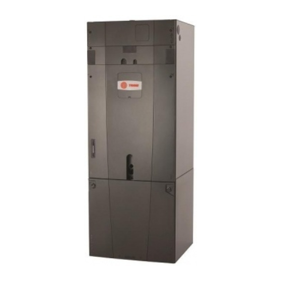
Installer's Guide
Air Handlers
Convertible 2 — 5 Ton
TAM7A0A24H21SC
TAM7A0C42H31SC
TAM7A0B30H21SC
TAM7A0C48H41SC
TAM7A0C36H31SC
TAM7B0C60H51SB
Only qualified personnel should install and service the equipment. The installation, starting up, and servicing of heating, ventilating, and
air-conditioning equipment can be hazardous and requires specific knowledge and training. Improperly installed, adjusted or altered
equipment by an unqualified person could result in death or serious injury. When working on the equipment, observe all precautions in the
literature and on the tags, stickers, and labels that are attached to the equipment.
November 2013
Scan or click to view
TAM7 Trouble
Shooting Video
Library
S S A A F F E E T T Y Y W W A A R R N N I I N N G G
18-GJ06D2-2A
Advertisement
Table of Contents

Related Manuals for Trane TAM7A0A24H21SC


Summary of Contents for Trane TAM7A0A24H21SC
- Page 1 Installer’s Guide Air Handlers Convertible 2 — 5 Ton TAM7A0A24H21SC TAM7A0C42H31SC TAM7A0B30H21SC TAM7A0C48H41SC TAM7A0C36H31SC TAM7B0C60H51SB Scan or click to view TAM7 Trouble Shooting Video Library S S A A F F E E T T Y Y W W A A R R N N I I N N G G Only qualified personnel should install and service the equipment.
- Page 2 . . N N o o t t e e : : Representative illustrations only included in this document. Most illustrations display the upflow configuration. 18-GJ06D2-2A ©2012 Trane...
-
Page 3: Table Of Contents
Table of Contents Installer Guide Notes ..... . . 4 Refrigerant Line ......25 Refrigerant System Layout . -
Page 4: Installer Guide Notes
Installer Guide Notes A A L L L L P P h h a a s s e e s s o o f f t t h h i i s s i i n n s s t t a a l l l l a a t t i i o o n n m m u u s s t t c c o o m m p p l l y y w w i i t t h h N N A A T T I I O O N N A A L L , , S S T T A A T T E E a a n n d d L L O O C C A A L L C C O O D D E E S S ! ! I I m m p p o o r r t t a a n n t t : : This Document is customer property and is to remain with t his unit. -
Page 5: Unit Design
Unit Design Table 1. Cabinet Penetration Important: Due to the unique design of this unit, which allows the electrical wiring to be routed within the insulation, do not screw, cut, or otherwise puncture the unit cabinet in any location other than the ones illustrated. Scre w s a re a llo w e d u p to 3- 3/4”... - Page 6 U U n n i i t t D D e e s s i i g g n n The Coil, Line Set, and Heater panels are removed using Phillips head screws. Removal requires #3 Size Phillips Coil and Heater panels must be removed prior to removing the Line Set panel.
-
Page 7: Unit Install Preparation
Unit Install Preparation Check for damage and report promptly to the carrier any damage found to the unit. Note: If the unit must be transported in a horizontal position, it must be laid on its back (marked “REAR” on carton). Note: After unit is removed from the carton, depress the Schrader valve, if equipped, to verify coil is pressurized. -
Page 8: Optional Equipment
Optional Equipment Accessory Number Description Fits Cabinet Size Electric Heater, 4kW, Breaker, RS-485 Control, 1 Ph BAYEVAC04BK1AA A to C Electric Heater, 4kW, Lugs, RS-485 Control, 1 Ph BAYEVAC04LG1AA A to C Electric Heater, 5kW, Breaker, RS-485 Control, 1 Ph BAYEVAC05BK1AA A to C Electric Heater, 5kW, Lugs, RS-485 Control, 1 Ph... -
Page 9: Optional Cabinet Disassembly
Optional Cabinet Disassembly Note: If the unit must be transported in a horizontal position, it must be laid on its back (marked “REAR” on carton). Note: To reassemble cabinet, follow the steps in reverse order. Ensure electrical connections are secure and the plug clips are engaged. Remove all four front panels. - Page 10 O O p p t t i i o o n n a a l l C C a a b b i i n n e e t t D D i i s s a a s s s s e e m m b b l l y y Disconnect the two wiring connections routed to the blower assembly.
- Page 11 O O p p t t i i o o n n a a l l C C a a b b i i n n e e t t D D i i s s a a s s s s e e m m b b l l y y Disconnect wires to the EEV motor and sensors.
- Page 12 O O p p t t i i o o n n a a l l C C a a b b i i n n e e t t D D i i s s a a s s s s e e m m b b l l y y Lift the Coil section up and away from the Blower section.
- Page 13 O O p p t t i i o o n n a a l l C C a a b b i i n n e e t t D D i i s s a a s s s s e e m m b b l l y y For extremely tight spaces where the cabinet needs to be rotated through a small opening, remove the top panel and all cross members.
-
Page 14: Placing Unit At Location
Placing Unit at Location Carry the unit to the installation location Reassembly by reversing the steps listed in Section 4 if disassembly was required. If cut, wire ties that held the sensor wiring must be replaced. Important: Under no conditions should metal strapping be attached to the unit to be used as support mechanisms for carrying or suspension purposes. -
Page 15: Unit Location Considerations
Coil and Heater H x W x D Compartment Unit Net Weight MODEL NUMBER (inches) Height * (pounds) (inches) TAM7A0A24H21SC 49.9 x 17.5 x 21.8 28.1 TAM7A0B30H21SC 55.7 x 21.3 x 21.8 33.9 TAM7A0C36H31SC 56.9 x 23.5 x 21.8 35.1 TAM7A0C42H31SC 56.9 x 23.5 x 21.8... -
Page 16: Four-Way Conversion
Four-Way Conversion To place the unit in the configuration your application requires (upflow, downflow, horizontal right, or horizontal left), simply turn the unit to that orientation. Remember to adjust the badge accordingly. Note: The air handlers are shipped from the factory suitable for four-way application. They are shipped in the downflow orientation. Re frig e ra n t Co n n e ctio n s Lo w Vo lta g e... - Page 17 F F o o u u r r - - W W a a y y C C o o n n v v e e r r s s i i o o n n Horiz ontal L e ft Co n fig u ra tio n Airflow Re frig e ra n t Lo w Vo lta g e...
-
Page 18: Applications
Ducted and Non-Ducted Applications Table 4. Non-Ducted Applications Suppl y Du ct C C A A U U T T I I O O N N H H A A Z Z A A R R D D O O U U S S V V A A P P O O R R S S ! ! F F a a i i l l u u r r e e t t o o f f o o l l l l o o w w t t h h i i s s C C a a u u t t i i o o n n c c o o u u l l d d r r e e s s u u l l t t i i n n p p r r o o p p e e r r t t y y d d a a m m a a g g e e o o r r p p e e r r s s o o n n a a l l i i n n j j u u r r y y . -
Page 19: Additional Unit Preparation
Additional Unit Preparation Considerations For proper installation the following items must be • Consider the overall space needed when external considered prior to moving the unit to its installation accessories are used, additional height and width site: requirements may exist. •... -
Page 20: Considerations
Setting the Unit — Vertical Installation Table 6. Secure Coil Remove Coil Panel. Remove screw from documentation packet. While the air handler is in the upflow position, use the supplied screw to secure the coil seal plate to cross member as shown. Important: The Coil Seal Plate and screw secure the coil in the center of the air handler. - Page 21 S S e e t t t t i i n n g g t t h h e e U U n n i i t t — — V V e e r r t t i i c c a a l l I I n n s s t t a a l l l l a a t t i i o o n n Table 8.
- Page 22 S S e e t t t t i i n n g g t t h h e e U U n n i i t t — — V V e e r r t t i i c c a a l l I I n n s s t t a a l l l l a a t t i i o o n n Table 10.
-
Page 23: Installations
Setting the Unit — Horizontal Installations Table 11. Secure Coil Remove Coil Panel. Remove screw from documentation packet. While the air handler is in the upflow position, use the supplied screw to secure the coil seal plate to cross member as shown. Important: The Coil Seal Plate and screw secure the coil in the center of the air handler. -
Page 24: Connecting The Duct Work
Connecting the Duct work Table 13. Duct Connection Considerations Important: Due to the unique design of this unit, which allows the electrical wiring to be routed within the insulation, do not screw, cut, or otherwise puncture the unit cabinet in any location other than the ones illustrated in this Installer Guide or in an approved accessory’s Installer Guide. -
Page 25: Refrigerant Line
Refrigerant Line Table 14. Refrigerant Line Connection Sizes Vapor Line Connection Liquid Line Connection Model TAM7A0A24H21SC TAM7A0B30H21SC TAM7A0C36H31SC TAM7A0C42H31SC TAM7A0C48H41SC TAM7B0C60H51SB Notes: This table indicates the tubing connection diameters at the indoor coil. A field supplied reducing coupling may be required. -
Page 26: Refrigerant Line Brazing
Refrigerant Line Brazing Table 15. Braze the Refrigerant Lines He a te r Remove Heater, Coil, and Line Set panels. Pa n e l Table 2, p. 5 Lin e Se t Pa n e l Co il Pa n e l Important: Do NOT unseal coil refrigerant connection stubs until ready to make connections. - Page 27 R R e e f f r r i i g g e e r r a a n n t t L L i i n n e e B B r r a a z z i i n n g g We t Ra g o n Ga s Te m p e ra tu re Se n s o r (GT) Important: Heat Sensitive Sensor.
- Page 28 R R e e f f r r i i g g e e r r a a n n t t L L i i n n e e B B r r a a z z i i n n g g Important: Do not open the service valves until the refrigerant lines 0350 and indoor coil leak check and evacuation are complete.
-
Page 29: Condensate Drain Piping
Condensate Drain Piping Table 16. Condensate Drain Piping Considerations • Condensate drain plumbing must comply with national, state, and local codes. • Do not connect the drain line to a closed drain system. • Do not use a torch or flame near the plastic drain pan coupling. •... - Page 30 C C o o n n d d e e n n s s a a t t e e D D r r a a i i n n P P i i p p i i n n g g Install a clean-out tee in the primary drain line for future maintenance.
-
Page 31: Electrical - Low Voltage
Electrical — Low Voltage Table 18. Low Voltage Maximum Wire Length 24 VOLTS The associated table defines the maximum WIRE SIZE MAX. WIRE LENGTH total length of low voltage wiring from the outdoor unit to the indoor unit, and to the 18 AWG 150 FT. - Page 32 E E l l e e c c t t r r i i c c a a l l — — L L o o w w V V o o l l t t a a g g e e Remove the control board from the control pocket by sliding the control pocket mounting plate out until the first stop is reached.
- Page 33 E E l l e e c c t t r r i i c c a a l l — — L L o o w w V V o o l l t t a a g g e e Make connections per hookup diagrams.
- Page 34 E E l l e e c c t t r r i i c c a a l l — — L L o o w w V V o o l l t t a a g g e e Figure 2.
- Page 35 E E l l e e c c t t r r i i c c a a l l — — L L o o w w V V o o l l t t a a g g e e Figure 3.
- Page 36 E E l l e e c c t t r r i i c c a a l l — — L L o o w w V V o o l l t t a a g g e e Figure 4.
- Page 37 E E l l e e c c t t r r i i c c a a l l — — L L o o w w V V o o l l t t a a g g e e S1 Dip Switch S2 Dip Switch Airflow Control (AFC) OUTDOOR TRANE U.S. INC. PART NO. LABEL Capacity (Tons) AC (System) 2 (Stages)
-
Page 38: Dip Switches
Co o l Off De la y INDOOR MODEL S1–1 S1–2 OD MULTIPLIER To rq u e TAM7A0A24H21SC +12V Airflo w Co n tro l (AFC) • Set the S1–4 dip switch for the number of stages on TAM7A0B30H21SC the outdoor unit. - Page 39 S2–1 S2–2 AC (S ys te m) CFM/TON CFM/TON 2 (S ta g e s ) 2 (Co mp re s s o r) TAM7A0A24H21SC INDOOR R NET 1 R NET 2 CFM/To n TAM7A0B30H21SC Co o l Off De la y...
-
Page 40: Indoor Blower Options
A conventional field supplied humidistat is required to control this function. YO J u m p e r TRANE U.S. INC. Do Not Cut P ART NO. LABEL Cut the BK jumper on the AFC. -
Page 41: Control Plate Reinstall
Control Plate Reinstall Slide control plate assembly into the control pocket until fully seated. The control plate should be flush with the outer edge of the unit. Replace coil panel making sure that the wires are located within the wire pass-through provided in the panel. Pa s s th ro u g h n o tch in co il a cce s s d o o r 18-GJ06D2-2A... -
Page 42: Electrical - High Voltage
Electrical — High Voltage Table 20. High Voltage Power Supply The high voltage power supply must match the equipment nameplate. W W A A R R N N I I N N G G Power wiring, including ground wiring must comply with national, L L I I V V E E E E L L E E C C T T R R I I C C A A L L C C O O M M P P O O N N E E N N T T S S ! ! sate, and local codes. - Page 43 E E l l e e c c t t r r i i c c a a l l — — H H i i g g h h V V o o l l t t a a g g e e BLACK If an electric heater IS NOT being installed, remove the pigtail harness from the documentation pack and connect it to the plug...
- Page 44 E E l l e e c c t t r r i i c c a a l l — — H H i i g g h h V V o o l l t t a a g g e e Reinstall all panels before starting the air handler Note: After replacing all panels, loosen the Line Set Panel screws approximately 1/4 —...
-
Page 45: Tam7 Outline Drawing
TAM7 OUTLINE DRAWING FLOW GAS LINE LIQ LINE Model Number CONTROL BRAZE BRAZE TAM7A0A24H21SC 49.9 17.5 14.5 39.6 14.5 24.4 TAM7A0B30H21SC 55.7 21.3 18.4 45.5 18.4 24.8 TAM7A0C36H31SC 56.9 23.5 20.5 46.7 20.5 10.3 24.2 TAM7A0C42H31SC 56.9 23.5 20.5 46.7 20.5... -
Page 46: Filters
Filters Table 22. Filter Considerations • A filter must be installed within the system. • A filter channel is provided in the unit at the bottom of the Blower/ Filter compartment. • For customer ease of filter maintenance, it is recommended that a properly sized remote filter grill(s) be installed for units that are difficult to access. -
Page 47: System Start Up
System Start Up Make sure all panels are securely in place and that all wiring has been properly dressed and secured. Set the system thermostat to OFF. DONE CANCEL Turn on electrical power disconnect(s) to apply power to the indoor and outdoor units. Set the system thermostat to ON. -
Page 48: Tam7 Sequence Of Operation
TAM7 Sequence of Operation Abbreviations 3. R-G contacts close on comfort control sending 24VAC to the G terminal of the AFC. • AFC = Airflow Control 4. The AFC micro-processor sends a command to the • EVC = Expansion Valve Control serial communicating blower motor to run at 100%. - Page 49 T T A A M M 7 7 S S e e q q u u e e n n c c e e o o f f O O p p e e r r a a t t i i o o n n O O D D T T w w o o S S t t a a g g e e ( ( c c o o o o l l i i n n g g m m o o d d e e ) ) N N o o t t e e : : The EHC has "lead-lag"...
-
Page 50: Checkout Procedures
Checkout Procedures The final phase of the installation is the system Checkout Procedures. The following list represents the most common items covered in a Checkout Procedure. Confirm all requirements in this document have been met. All wiring connections are tight and properly secured. Supply registers and return grilles are open, unobstructed, and air filter is installed. - Page 51 N N o o t t e e s s 18-GJ06D2-2A...
- Page 52 Trane offers a broad portfolio of advanced controls and HVAC systems, comprehensive building services, and parts. For more information, visit www.Trane.com. Trane has a policy of continuous product and product data improvements and reserves the right to change design and specifications without notice. ©2012 Trane...