Table of Contents
Advertisement
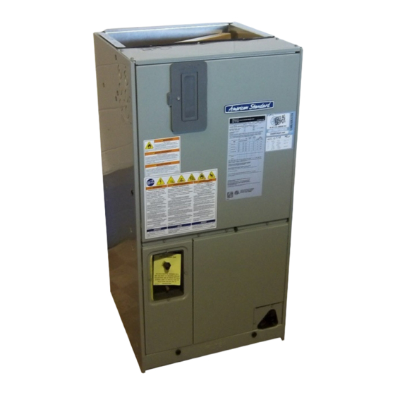
Installer's Guide
Convertible Air Handlers
1-1/2 – 5 Ton
2/4TEC3F18B1000A
2/4TEC3F24B1000A
2/4TEC3F30B1000A
2/4TEC3F36B1000A
WARNING:
ALL phases of this installation must comply with NATIONAL, STATE AND LOCAL CODES
IMPORTANT — This Document is customer property and is to remain with this unit. Please return to service information
pack upon completion of work.
A. GENERAL INFORMATION
WARNING
!
THIS INFORMATION IS FOR USE BY INDIVIDUALS
HAVING ADEQUATE BACKGROUNDS OF ELECTRICAL
AND MECHANICAL EXPERIENCE. ANY ATTEMPT TO
REPAIR A CENTRAL AIR CONDITIONING PRODUCT
MAY RESULT IN PERSONAL INJURY AND/OR PROP-
ERTY DAMAGE. THE MANUFACTURER OR SELLER
CANNOT BE RESPONSIBLE FOR THE INTERPRETA-
TION OF THIS INFORMATION, NOR CAN IT ASSUME
ANY LIABILITY IN CONNECTION WITH ITS USE.
CAUTION
!
To prevent shortening its service life, the air handler
should not be used during the finishing phases of con-
struction. The low return air temperatures can lead to
the formation of condensate. Condensate in the pres-
ence of chlorides and fluorides from paint, varnish,
stains, adhesives, cleaning compounds, and cement
creates a corrosive condition which may cause rapid
deterioration of the cabinet and internal components.
These instructions do not cover all variations in systems
or provide for every possible contingency. Should fur-
ther information be desired or particular problems arise
which are not covered sufficiently by this manual, con-
tact your local distributor or the manufacturer as listed
on the air handler nameplate.
These air handlers are shipped from the factory in the
Upflow or horizontal right configuration and are fully
convertible to downflow or horizontal left. Refer to
Section B beginning on page 3 for additional informa-
tion.
INSPECTION
Check carefully for any shipping damage. This must
be reported to and claims made against the transpor-
tation company immediately. Check to be sure all
major components are in the unit. Any missing parts
should be reported to your supplier at once, and re-
placed with authorized parts only.
2/4TEC3F42C1000A
2/4TEC3F48B1000A
2/4TEC3F55B1000A
2/4TEC3F60B1000A
HAZARDOUS VOLTAGE - DISCONNECT POWER BEFORE SERVICING
Contents
General Information
Upflow
Electrical — Power Wiring
Hook-up Diagrams
Outline Drawing
CAUTION
!
Cardboard packing material must be removed from in-
side the blower assembly before starting the unit.
Failure to do so may cause indoor blower motor failure.
INSTALLATION LIMITATIONS & RECOMMENDATIONS
The general location of the air handler is normally
selected by the architect, contractor and/or home owner
for the most effective application and satisfaction.
NOTE: CONDENSATION MAY OCCUR ON THE SUR-
FACE OF THE AIR HANDLER WHEN INSTALLED IN AN
UNCONDITIONED LOCATION. WHEN UNITS ARE IN-
STALLED IN UNCONDITIONED SPACES, VERIFY THAT
ALL ELECTRICAL AND REFRIGERANT LINE PEN-
ETRATIONS ON THE AIR HANDLER ARE SEALED
COMPLETELY.
18-GE08D1-7
1
3
3
4
6
7
8
8
8
9
10
10
11
14
16
Advertisement
Table of Contents

Related Manuals for Trane 2/4TEC3F18B1000A


Summary of Contents for Trane 2/4TEC3F18B1000A
- Page 1 Installer’s Guide 18-GE08D1-7 Convertible Air Handlers 1-1/2 – 5 Ton 2/4TEC3F18B1000A 2/4TEC3F42C1000A 2/4TEC3F24B1000A 2/4TEC3F48B1000A 2/4TEC3F30B1000A 2/4TEC3F55B1000A 2/4TEC3F36B1000A 2/4TEC3F60B1000A WARNING: HAZARDOUS VOLTAGE - DISCONNECT POWER BEFORE SERVICING ALL phases of this installation must comply with NATIONAL, STATE AND LOCAL CODES IMPORTANT — This Document is customer property and is to remain with this unit. Please return to service information pack upon completion of work.
- Page 2 APPROX. 3/4" FLANGES ON FIELD FLOOR FABRICATED DUCT OR PLENUM HEADER JOIST JOISTS NAILS NAILS FLOOR OPENING - SIZE MODEL NO. HEADER HEADER TAYBASE100 23-3/4 14-13/16 TAYBASE101 21-3/4 14-13/16 MIN. SPACING TO TAYBASE102 26-3/4 14-13/16 1" 1" ANY COMBUSTIBLE MATERIAL. 18-GE08D1-6 © 2008 Trane...
- Page 3 B. TWO PIECE CABINET DISASSEMBLY Trane. Only heaters built by Trane are approved for use in the air handler. These heaters have been designed (OPTIONAL) and tested in accordance with UL standards to provide NOTE: For easier installation into tight areas, the 4 safe and reliable operation.
- Page 4 (See Figure 5). Reinstall coil assembly. 18-GE08D1-6 © 2008 Trane...
- Page 5 Installer’s Guide the coil. Remove drip tray by gently breaking the drain pan, Figure 9. Fill the bend in the the seal between the drip tray and drain pan. baffle which fits the inner edge of the drain pan b. Remove the factory installed baffle assembly with non-acetic acid RTV type adhesive/sealant from the apex of the coil by using a 5/16"...
- Page 6 Installer’s Guide k. If a return duct is connected to the air handler, it ceed the face velocity of the filter being used. must be the same dimensions as the return The factory installed filter should then be opening shown in the outline drawing. removed from the unit.
- Page 7 Installer’s Guide j. No sheetmetal screws may be used to attach re- turn ductwork on the side of the unit. k. Openings where field wiring enters the cabinet must be completely sealed. Location of power entry is shown on the outline drawing. Use 2.5"...
- Page 8 Installer’s Guide Convertible duct flanges are provided on the discharge Flange Attachment opening to provide a “flush fit” for 3/4" or 1-1/2" duct board applications. See the Outline drawing for sizes of the duct connections. After the duct is secured, seal around the supply duct to prevent air leakage.
- Page 9 Installer’s Guide 2. Field supplied tubing should be cut square, round 1. The primary drain line must be trapped with a mini- and free of burrs at the connecting end. Clean the mum of 2" water seal as shown in Figures 15 & 16. tubing to prevent contaminants from entering the Do not use preformed 3/4"...
- Page 10 Installer’s Guide 2. The selection of wire and fuse sizes should be made MANUFACTURED TRAPS according to the Minimum Branch Circuit Ampacity and the Maximum Overcurrent Device listed on the unit nameplate. 3. Field wiring diagrams for electric heaters and unit accessories are shipped with the accessory.
- Page 11 Installer’s Guide 2/4TEC AIR HANDLER WITH HEAT PUMP WITH SUPPLEMENTAL HEAT From Dwg. B801082 Rev. 2 18-GE08D1-7...
- Page 12 Installer’s Guide 2/4TEC AIR HANDLERS WITH SINGLE SPEED COOLING UNIT, 1 STAGE HEAT From Dwg. B801083 Rev. 2 18-GE08D1-7...
- Page 13 Installer’s Guide 2/4TEC AIR HANDLER WITH SINGLE SPEED COOLING UNIT, 2 STAGE HEAT From Dwg. B801081 Rev. 2 18-GE08D1-7...
- Page 14 Installer’s Guide OUTLINE DRAWING FOR 2/4TEC3F18-60B 18-GE08D1-7...
- Page 15 Installer’s Guide 2/4TEC AIR HANDLER DIMENSIONAL DATA 2/4TEC3F48B & 60B are two piece cabinets MODEL 21.0" 2/4TEC3F18B 43.00 21.50 2/4TEC3F24B 43.00 21.50 2/4TEC3F30B 45.00 21.50 2/4TEC3F36B 45.00 21.50 2/4TEC3F42C 51.75 23.50 2/4TEC3F48B 57.90 23.50 2/4TEC3F55B 57.90 26.00 2/4TEC3F60B 57.90 23.50 18-GE08D1-7...
- Page 16 3. Check circuit protection for proper size per nameplate specifications ............. [ ] 4. Check control box panel — in place and secured ..................[ ] NOTE: OPERATION OF HEATERS MUST BE CHECKED DURING THE OPERATION CHECK OF THE TOTAL SYSTEM. Trane 6200 Troup Highway Tyler, TX 75707 www.trane.com...