Table of Contents
Advertisement
Installer's Guide
Convertible Air Handlers
2 — 5 Ton
TEM6A0B24H21SC
TEM6A0B30H21SC
TEM6A0C36H31SC
TEM6A0C42H41SC
TEM6A0C48H41SC
TEM6B0C60H51SA
Only qualified personnel should install and service the equipment. The installation, starting up, and servicing of heating, ventilating, and air-conditioning
equipment can be hazardous and requires specific knowledge and training. Improperly installed, adjusted or altered equipment by an unqualified person
could result in death or serious injury. When working on the equipment, observe all precautions in the literature and on the tags, stickers, and labels that
are attached to the equipment.
July 2022
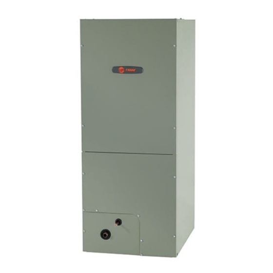
The TEM6 series air handler is designed for installation in a closet,
utility room, alcove, basement, crawlspace or attic. These versatile
units are applicable to air conditioning and heat pump
applications. Several models are available to meet the specific
requirements of the outdoor equipment. Field installed electric
resistance heaters are available.
S S A A F F E E T T Y Y W W A A R R N N I I N N G G
1 1 8 8 - - G G F F 7 7 4 4 D D 1 1 - - 1 1 R R - - E E N N
Advertisement
Table of Contents

Related Manuals for Trane TEM6A0B24H21SC


Summary of Contents for Trane TEM6A0B24H21SC
- Page 1 Installer’s Guide Convertible Air Handlers 2 — 5 Ton TEM6A0B24H21SC TEM6A0B30H21SC TEM6A0C36H31SC TEM6A0C42H41SC TEM6A0C48H41SC TEM6B0C60H51SA The TEM6 series air handler is designed for installation in a closet, utility room, alcove, basement, crawlspace or attic. These versatile units are applicable to air conditioning and heat pump applications.
- Page 2 SAFETY SECTION AIR HANDLERS I I m m p p o o r r t t a a n n t t : : This document contains a wiring diagram, W W A A R R N N I I N N G G a parts list, and service information.
- Page 3 S S A A F F E E T T Y Y S S E E C C T T I I O O N N A A I I R R H H A A N N D D L L E E R R S S W W A A R R N N I I N N G G N N o o t t e e : : Air handlers have been evaluated in accordance with the Code of Federal Regulations, Chapter...
-
Page 4: Table Of Contents
Table of Contents Features ........5 Heater Pressure Drop Table . -
Page 5: Features
Features Table 1. Standard Features additional 1/4” rise over the width or depth of the unit is allowed to create additional sloping towards • MULTI-POSITION UPFLOW, DOWNFLOW, HORIZONTAL LEFT the drain. Unit must be positioned between level AND HORIZONTAL RIGHT and ¼”... - Page 6 F F e e a a t t u u r r e e s s Negative 5. R R e e f f r r i i g g e e r r a a n n t t P P i i p p i i n n g g Pressure Refrigerant piping external to the unit shall be sized in accordance with the instructions of the...
- Page 7 F F e e a a t t u u r r e e s s Figure 2. Dip Switches 9. W W i i r r i i n n g g Consult all schematic and pictorial wiring diagrams COOLING HEATING FAN OFF...
- Page 8 F F e e a a t t u u r r e e s s the compressor contactor of the outdoor unit. The 13. O O p p e e r r a a t t i i o o n n a a l l a a n n d d C C h h e e c c k k o o u u t t P P r r o o c c e e d d u u r r e e s s contactor will close and start the compressor and To obtain proper performance, all units must be condenser fan motor.
-
Page 9: Field Wiring
Field Wiring Single Stage, Cooling Only Single Stage, HP Outdoor Outdoor Thermostat Air Handler Thermostat Air Handler Unit Unit 24 VAC HOT 24 VAC HOT 24 VAC 24 VAC Common Common Blue Blue COOL/HEAT COOL/HEAT 1st STAGE 1st STAGE HEATING HEATING 2nd STAGE 2nd STAGE... - Page 10 F F i i e e l l d d W W i i r r i i n n g g 2 Stage, 2 Step, Cooling Only 2 Stage, 2 Step, HP Outdoor Outdoor Thermostat Air Handler Thermostat Air Handler Unit Unit 24 VAC HOT...
-
Page 11: Electrical Data
Electrical Data 18-GF74D1-1R-EN... -
Page 12: Performance And Electrical Data
Performance and Electrical Data Table 4. Air Flow Performance TEM6A0B24H21SC COOLING AIRFLOW PERFORMANCE, WET COIL, NO FILTER, NO HEATER OUTDOOR DIP SWITCH SETTING EXTERNAL STATIC PRESSURE SPEED AIRFLOW AIRFLOW UNIT SIZE SETTING SETTING POWER (TONS) 353 CFM/ Watts 401 CFM/... - Page 13 P P e e r r f f o o r r m m a a n n c c e e a a n n d d E E l l e e c c t t r r i i c c a a l l D D a a t t a a Table 6.
- Page 14 P P e e r r f f o o r r m m a a n n c c e e a a n n d d E E l l e e c c t t r r i i c c a a l l D D a a t t a a Table 8.
- Page 15 P P e e r r f f o o r r m m a a n n c c e e a a n n d d E E l l e e c c t t r r i i c c a a l l D D a a t t a a Table 10.
- Page 16 P P e e r r f f o o r r m m a a n n c c e e a a n n d d E E l l e e c c t t r r i i c c a a l l D D a a t t a a Table 12. Electrical Data TEM6A0B24H21SC HEATER DATA 240 Volt 208 Volt No.
- Page 17 P P e e r r f f o o r r m m a a n n c c e e a a n n d d E E l l e e c c t t r r i i c c a a l l D D a a t t a a Table 14.
-
Page 18: Minimum Airflow Cfm
Minimum Airflow CFM TEM6A0B24H21SC, TEM6A0B30H21SC Heater Minimum Heater Airflow CFM With Heat Pump Without Heat Pump BAYHTR1504BRK, BAYHTR1504LUG BAYHTR1505BRK, BAYHTR1505LUG BAYHTR1508BRK, BAYHTR1508LUG BAYHTR1510BRK, BAYHTR1510LUG BAYHTR1517BRK 1050 BAYHTR3510LUG BAYHTR3517LUG TEM6A0C36H31SC, TEM6A0C42H41SC Heater Minimum Heater Airflow CFM With Heat Pump Without Heat Pump... - Page 19 M M i i n n i i m m u u m m A A i i r r f f l l o o w w C C F F M M TEM6A0B24H21SC, TEM6A0B30H21SC Airflow Performance with Auxiliary Heat...
-
Page 20: Outline Drawing
Outline Drawing NOTE: THIS UNIT IS APPROVED FOR INSTALLATION CLEARANCES TO COMBUSTIBLE MATERIAL AS STATED ON THE UNIT RATING NAMEPLATE DWG D806626 PRODUCT DIMENSIONS Flow Gas Line Air Handler Model Control Braze TEM6A0B24, 30 46.77 18.50 16.50 16.75 4.68 7.33 20.09 TEM6A0C36, 42 51.27... -
Page 21: Heater Pressure Drop Table
Heater Pressure Drop Table Number of Racks Heater Racks Airflow Heater Model No. of Racks Air Pressure Drop — Inches W.G. BAYHTR1504 1800 0.02 0.04 0.06 0.14 BAYHTR1505 1700 0.02 0.04 0.06 0.14 BAYHTR1508 1600 0.02 0.04 0.06 0.13 BAYHTR1510 1500 0.02 0.04... -
Page 22: Coil Conversion Instructions
Coil Conversion Instructions Table 16. Downflow Figure 4. All models Follow the conversion steps when installing the air handler in downflow configuration. Remove the front panels from the air handler. The coil and line set panel do not need to be separated. Remove the fasteners on both sides of the coil. - Page 23 C C o o i i l l C C o o n n v v e e r r s s i i o o n n I I n n s s t t r r u u c c t t i i o o n n s s Table 16.
- Page 24 C C o o i i l l C C o o n n v v e e r r s s i i o o n n I I n n s s t t r r u u c c t t i i o o n n s s Table 16.
-
Page 25: Coil Conversion
C C o o i i l l C C o o n n v v e e r r s s i i o o n n I I n n s s t t r r u u c c t t i i o o n n s s Coil Conversion Table 17. - Page 26 C C o o i i l l C C o o n n v v e e r r s s i i o o n n I I n n s s t t r r u u c c t t i i o o n n s s Table 17.
- Page 27 C C o o i i l l C C o o n n v v e e r r s s i i o o n n I I n n s s t t r r u u c c t t i i o o n n s s Figure 15.
- Page 28 C C o o i i l l C C o o n n v v e e r r s s i i o o n n I I n n s s t t r r u u c c t t i i o o n n s s Figure 19.
- Page 29 C C o o i i l l C C o o n n v v e e r r s s i i o o n n I I n n s s t t r r u u c c t t i i o o n n s s Figure 23.
- Page 30 C C o o i i l l C C o o n n v v e e r r s s i i o o n n I I n n s s t t r r u u c c t t i i o o n n s s Figure 27.
-
Page 31: Checkout Procedures
Checkout Procedures The final phase of the installation is the system Checkout Procedures. The following list represents the most common items covered in a Checkout Procedure. Confirm all requirements in this document have been met. ☐ All wiring connections are tight and properly secured. ☐... - Page 32 About Trane and American Standard Heating and Air Conditioning Trane and American Standard create comfortable, energy efficient indoor environments for residential applications. For more information, please visit www.trane.com or www.americanstandardair.com. The manufacturer has a policy of continuous data improvement and it reserves the right to change design and specifications without notice. We are committed to using environmentally conscious print practices.